This manual must only be used by a qualifi ed heating installer/service technician. Read all instructions, including this manual and
all other information shipped with the boiler, before installing. Perform steps in the order given. Failure to comply could result in
severe personal injury, death or substantial property damage.
Part number 550-100-214/1220
Advanced Manual
Multiple Boiler Installation & Settings + Single Boiler Advanced Settings
CONDENSING GAS BOILER
110/155
Evergreen
®
Control — Advanced mode . . . . . . . 3
Multiple boiler installations . . . . . . . . . . . . . 6
Fast-Track Setup — Requirements by Boiler . . . . 9
Fast-Track Setup — Steps . . . . . . . . . . . . . 10
Fast-Track Setup — The WIZARD . . . . . . . . . 11
Fast-Track Setup — Typical Application A . . . . 14
Fast-Track Setup — Typical Application B . . . . 18
Fast-Track Setup — Typical Application C . . . . 22
Field wiring (see wiring diagram, ) . . . . . . . . . . . 26
Wiring diagram — schematic . . . . . . . . . . . 34
Wiring diagram — ladder . . . . . . . . . . . . . 35
Zoning with the EVG Control . . . . . . . . . . . . 36
Control operation. . . . . . . . . . . . . . . . . . 41
Available control settings – Advance Mode . . . . 43
System Type presets . . . . . . . . . . . . . . . . 45
CONTRACTOR menus. . . . . . . . . . . . . . . . 46
BOILER SETTINGS menu . . . . . . . . . . . . . . 47
NETWORK SETTINGS menu. . . . . . . . . . . . . 48
ROTATION AND SEQUENCE . . . . . . . . . . . . . 49
Network Boiler PRIORITY menus . . . . . . . . . 52
Single Boiler PRIORITY menus . . . . . . . . . . . 54
ASSIGN INPUTS menu . . . . . . . . . . . . . . . 56
AUX PUMP/OUTPUT options . . . . . . . . . . . . 57
MAINTENANCE, DATE AND TIME menus . . . . . . 58
Follow all instructions for installation, start-
up and servicing in the Evergreen
®
boiler
manual.
Use this Advanced Manual for multiple
boiler installation guidelines and control set-
tings and for single boiler advanced control
settings.
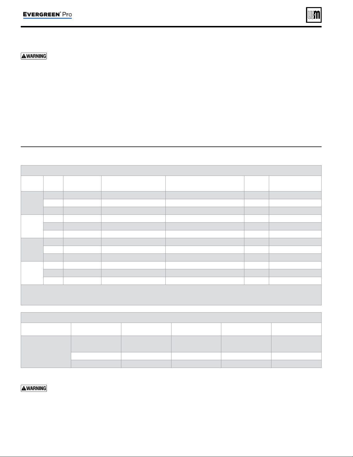
HAZARD DEFINITIONS
The following defi ned terms are used throughout this manual to
bring attention to the presence of hazards of various risk levels
or to important information concerning the life of the product.
Indicates presence of hazards that will cause
severe personal injury, death or substantial
property damage.
Indicates presence of hazards that can cause
severe personal injury, death or substantial
property damage.
Indicates presence of hazards that will or can
cause minor personal injury or property dam-
age.
Indicates special instructions on installation,
operation or maintenance that are important
but not related to personal injury or property
damage.
IMPORTANT
THE OUTDOOR SENS OR SUPPLIED WITH THE
BOILER MU ST BE INSTALLED UNLESS EXEMPT-
ED BELOW:
In accordance with
Section 303 of the 2007 Energy Act, this
boiler is equipped with a feature that saves energy by reducing
the boiler water temperature as the heating load decreases.
This feature is equipped with an override which is provided
primarily to permit the use of an external energy management
system that serves the same function.
THIS OVERRIDE MUST NOT BE USED UNLESS AT LEAST
ONE OF THE FOLLOWING CONDITIONS IS TRUE:
• An external energy management system is installed that reduces
the boiler water temperature as the heating load decreases.
• This boiler is not used for any space heating.
• This boiler is part of a modular or multiple boiler system hav-
ing a total input of 300,000 BTU/hr or greater.
• This boiler is equipped with a tankless coil (not applicable to
Evergreen
®
).
If the outdoor sensor is not used, the following
changes must be made to control settings dur-
ing control setup:
TARGET ADJUST (in priority menus) must be
set either to NONE (constant supply tempera-
ture) or 0–10VDC (remote target).
WWSD must be set to OFF.
Part number 550-100-214/1220
– 2 –
CONDENSING GAS BOILER — 110/155 Advanced Manual
Contents
Evergreen
®
Control — Advanced mode
Evergreen
®
control overview
Basic Boiler Features:
• Easy confi guration with WIZARD step-by-step setup including
on-screen help.
• BASIC boiler settings mode for streamlined menu navigation of
essential settings.
• Three customizable input/output pairs—use as a 3-Zone control
or a 3-Priority control.
• Confi gure outputs to control System Pumps or 120 VAC Auxiliary
equipment.
• System type presets simplify system temperature selection.
• 0-10VDC Input can modulate boiler fi ring rate or target.
• Integral outdoor reset with warm weather shutdown.
Advanced Boiler Features:
• ADVANCED boiler settings mode unlocks all features and cus-
tomizable parameters.
• Manage multiple types of System Pumps or 120 VAC Auxiliary
accessories.
• Manage staged heating sources using the Additional Heat Demand
feature.
• BMS integration with standard MODBUS.
Evergreen
®
control setup
1. Set control parameters using the WIZARD option provided
on initial start-up or manually enter parameters using control
menus explained later in this manual.
2. See
Fast-Track setup
instructions beginning on page 9 for
example applications and minimum settings required (using
factory defaults).
3. This manual provides set-up information for a single-boiler
advanced settings and for all multiple boiler applications.
Boiler Model, Altitude and Fuel Type are critical settings.
Failure to set correctly could result in severe personal injury,
death or substantial property damage.
Temperature settings — You must ensure that the Evergreen
®
control is set for the proper water temperatures for the system.
Excessive water temperature can cause signifi cant property
damage in some applications.
Multi-temperature systems — If the heating system in-
cludes circuits that require lower temperature water (radiant
slab circuits, for example) as well as higher temperature circuits
(DHW, fi nned tube baseboard, etc.), it is recommended to protect
low-temperature circuits with limit controls that are wired to
an Evergreen
®
control external limit circuit. Failure to provide
regulation can result in substantial property damage.
Multiple Boiler (Network) Features:
(see next page for explanation of Priorities)
• Create a network of up to 8 boilers using built-in con-
trols.
• Master boiler controls the modulation and sequencing
of boilers on the network to achieve desired system
supply temperature.
• Use ALL boiler inputs, not just the fi rst and last boilers,
up to 24 customizable inputs across boiler network (3
per unit, maximum of 8 boilers on network).
• Two (2) available Network Priorities allow multiple
system types/temperature zones.
• Direct-connected DHW tanks (or other heating zones)
can be piped and wired locally to any boiler in the sys-
tem, not just the fi rst or the last.
• Three system modulation types—SERIES, PARALLEL,
AND SMART.
• Three (3) Lead boiler rotation modes (plus OFF).
• Limit the fi ring rate for each Network Priority indepen-
dently when heat demands are mismatched using the
Max System Rate parameter.
• Fire multiple boilers at initial call for heat to start up
quickly for high demand applications using the Mini-
mum Boilers parameter.
• Won’t interrupt a Local heat demand (such as direct-
connected DHW tank) to satisfy Network heat demand
unless all available boilers are at maximum input.
• Simple, 2-wire boiler-to-boiler communication con-
nection.
Evergreen
®
control operation
• The control responds to signals from:
• Room thermostats
• DHW aquastats (if used)
• Temperature sensors — boiler return, boiler supply,
fl ue temperature and, when used, system supply and
system return, outdoor temperature.
For optimal
performance, it is recommended to install the
system supply and return sensors.
• The control automatically adjusts blower speed (and gas
fl ow rate) to match boiler output to space heating and/
or DHW heating demand.
• The control provides three inputs and three outputs (for
circulators or auxiliary devices) plus a boiler circulator
output.
• Outdoor reset must be used in all applications that are
not exempt as described on page 2 .
• The outdoor temperature is used for supply tem-
perature reset operation and for the warm weather
shutdown (WWSD) option.
• See “Outdoor reset operation” on page 4 for com-
plete explanation of outdoor reset settings.
• System presets
• The Evergreen
®
control provides presets by system
type (see Figure 21, page 45 for complete list).
Part number 550-100-214/1220
– 3 –
CONDENSING GAS BOILER — 110/155 Advanced Manual

Evergreen
®
Control — ADVANCED mode (continued)
Part number 550-100-214/1220
– 4 –
CONDENSING GAS BOILER — 110/155 Advanced Manual
EVG contr ol Priorities & Input/Outputs
• For heating installations with multiple systems, the EVG
control uses PRIORITIES to determine the order of opera-
tion of the systems.
• The control’s MAX and MIN time settings determine the
maximum and minimum times a system will be oper-
ated before being turned off to allow another system to
operate.
• A typical example is DHW priority — heat demand from
the DHW system is given preference over space heating
if assigned to Priority 1.
• Each PRIORITY has its own set of operating parameters.
• The control prompts the user to select the system type
(fi nned tube baseboard, DHW, etc.) and is factory pro-
grammed with parameters suited to each of these system
types.
• The user can also choose CUSTOM to create a system
type.
• The EVG control provides up to three
PRIORITIES for single
boiler applications and up to four priorities for network boiler
applications. The order of operation is:
• Single boilers: PRIORITY 1, PRIORITY 2, PRIORITY 3.
• Network boilers: LOCAL PRIORITY 1, NETWORK
PRIORITY 1, NETWORK PRIORITY 2, LOCAL PRI-
ORITY 2.
• For each boiler in a network, this provides up to two
LOCAL priorities, used for heating systems piped directly
to the boiler, such as DHW tanks.
• NETWORK priorities are used for heating systems con-
nected in the primary heating loop and supplied by the
boiler network.
• Each boiler has three
INPUT/OUTPUT pairs (INPUT/OUT-
PUT 1, 2 and 3).
• Control setup prompts the user to assign each of these I/O
pairs to a PRIORITY. The EVG control then knows which
system (priority) to operate when any input assigned to
that priority receives a call for heat.
• The EVG controls respond to heat calls based on the
order of the assigned priorities and the timings set for
each priority’s operation.
Boiler circulator
• The boiler circulator is shipped loose with the boiler for fi eld
installation.
• The 120 VAC power output to the boiler circulator is provided
by a terminal block located on the boiler’s left cabinet wall.
For each of the priorities, the control can be setup to run the
boiler pump or to leave it off. It is recommended to set Boiler
Circulator to OFF for directly piped DHW systems with its
own circulator.
The boiler circulator must be installed and con-
nected. Flow through the boiler must be provided
during all times of operation. Failure to do so can
result in severe personal injury, death or substantial
property damage.
Multiple boiler operation
• The Evergreen
®
boiler has an auto detection feature for
multiple boiler networks. The Master will automatically
detect the presence of the other boilers wired to the network.
• There will be a 30 second to 1 minute period until the Master
may see the shadow boilers.
• Each shadow boiler must be assigned a network address,
from 2 through 8. The address for each boiler must be
unique, NOT selected for any other boiler.
• Afterwards, the Master will build a network based on the
communications shared. If a boiler loses communication,
the Master will automatically re-assign the lost boiler to
where it was before once it is back on the network.
• When network inputs turn on, the Master boiler will enter
the Network Modulation routine.
• Using system sensors, the Master will modulate the entire
network to meet the energy requirements of Network Prior-
ity 1 and Network Priority 2 inputs when they are on.
• When a Local Priority input becomes active (switch closes),
modulation for that input is not controlled by the Master,
but instead is left to that local boiler using its own local Heat
Exchanger Inlet and Outlet sensors.
• Each of the three (3) inputs on the Master or any of the
Shadow boilers can be assigned as Network Priority 1 or 2
or assigned as Local Priority 1 or 2. Network Priority settings
are common across all the boilers. These Network Priority
settings can only be adjusted from the Master boiler.
Sequence of operation
• Figure 19, page 42 is a summary of the operating sequence
for the Evergreen
®
control.
• The statuses shown appear in the display as the
Evergreen
®
control cycles the boiler.
• The display will display red (solid or fl ashing) if a prob-
lem has been detected.
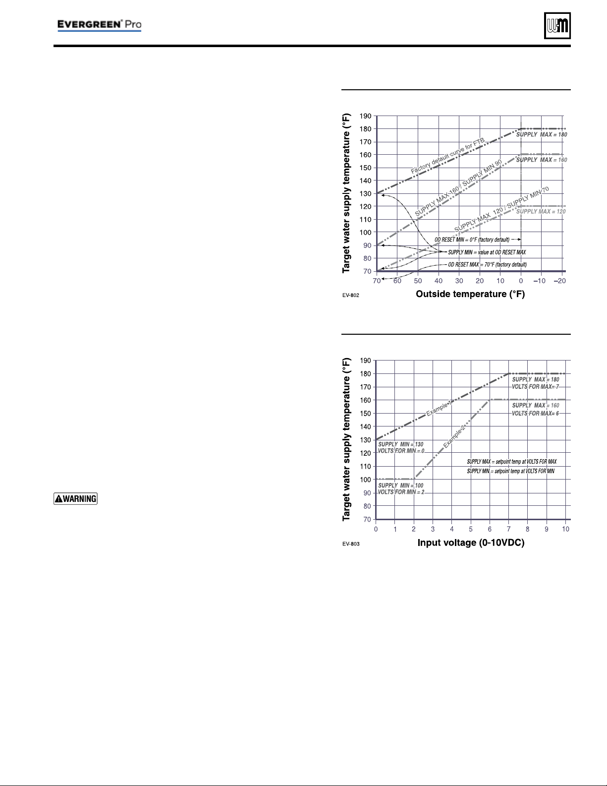
Outdoor reset oper ation
1. Calculates target temperature for space heating zones based
on outdoor temperature.
2. For an explanation of the target temperatures and associated
outdoor temperatures, see Figure 1, page 5 .
3. The temperature settings discussed below are accessed in
the priority menu for the applicable system. For detailed
explanations of the priority menus, see Figure 28, page 52 .
SUPPLY MAX
1. Set SUPPLY MAX to the required supply water temperature
for the system at design maximum heat loss (typically 180°F
for fi nned tube baseboard on new installations).
SUPPLY MIN
1. SUPPLY MIN should equal the desired minimum supply
water temperature for the system.
2. This could be set as low as 70°F, which would supply “zero
heat” when outdoor temperature is 70°F, because supply
water temp would equal room temp.
3. See examples in Figure 1 .
Evergreen
®
Control — ADVANCED mode (continued)
Part number 550-100-214/1220
– 5 –
CONDENSING GAS BOILER — 110/155 Advanced Manual
Figure 1 Outdoor reset operation
Figure 2 Remote target operation
OD RESET MAX
1. OD RESET MAX means the outdoor temperature at which the
target temperature reaches its minimum (SUPPLY MIN).
2. In the examples of Figure 1 , this occurs at 70 °F (the factory
default).
OD RESET MIN
1. OD RESET MIN means the outdoor temperature at which the
target temperature reaches its maximum value (SUPPLY MAX).
2. In the examples of Figure 1 , this occurs at 0°F outside (the factory
default setting).
3. OD RESET MIN should equal the ODT (outdoor design tem-
perature) for the installation’s location.
Remote target operation (0–10VDC input)
1. This function allows a remote analog input to regulate the sup-
ply temperature for control operation/modulation. This can be
done for any priority, including network and local priorities for
multiple boiler networks.
2. The settings discussed below are accessed in the priority menu
for the applicable system. For detailed explanations of the priority
menus, see Figure 28, page 52 .
3. See Figure 2 for an explanation of target temperature vs voltage
when using remote target operation.
4. In the priority menu for the applicable system, select 0-10V for
the TARGET ADJUST setting.
5. In the same priority menu, select the VOLTS FOR MIN and VOLTS
FOR MAX values. VOLTS FOR MIN sets the voltage value for the
desired minimum supply temperature. VOLTS FOR MAX sets
the voltage value for the desired maximum supply temperature.
Remote modulation operation
(0–10VDC input) — Single boilers only
Using an external multiple boiler controller — Remote
modulation using an external controller only works
with each boiler set up as a SINGLE boiler in the EVG
Control setup.
1. Use this option for single boilers only. To use 0–10VDC for re-
mote modulation, go to Contractor Menu -> Assign Inputs. Then
change Input 1’s source to 0–10V. The priority that is assigned to
Input 1 cannot not be used by any other Input.
2. The boiler comes on at 0.9VDC and turns off at 0.8VDC. 2 VDC
= 20% input. 10 VDC = 100% input. These voltage settings are
not adjustable.
Part number 550-100-214/1220
– 6 –
CONDENSING GAS BOILER — 110/155 Advanced Manual
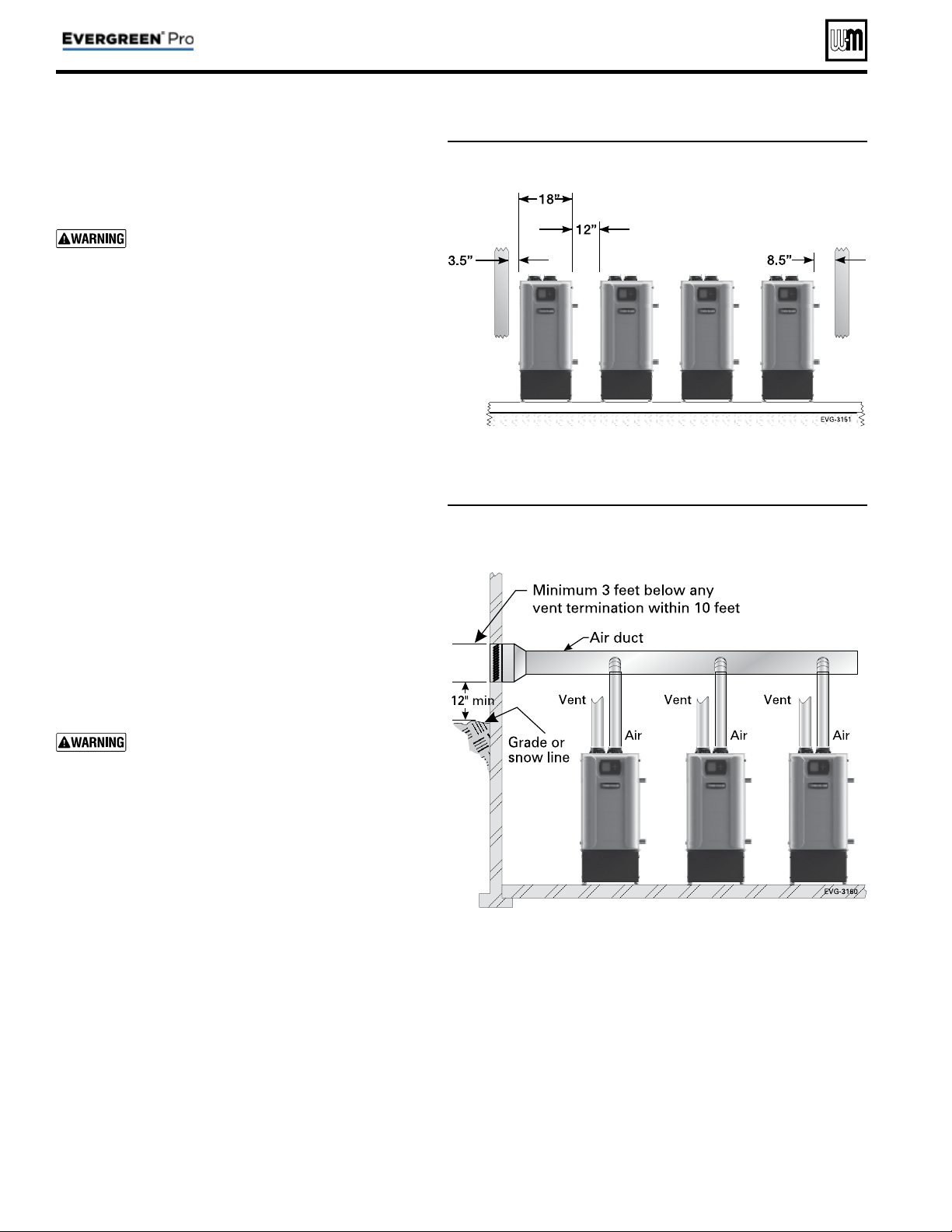
Placing multiple boilers
1. Locate multiple boilers with spacings shown in Figure 3 .
Provide the indicated clearances around boilers for access
and servicing.
If recommended dimensions are not possible,
provide at least the minimum clearances given
in the Evergreen
®
boiler manual. Also follow
local codes.
2. If boilers are fl oor-mounted, construct a boiler foundation
if boiler room fl oor is uneven or if there is a danger of
fl ooding. Size the foundation to allow for clearance and
spacing dimensions shown in Figure 3 .
3. Provide a minimum 30-inch walkway in front of the boil-
ers to ensure accessibility.
4. Uncrate, assemble and mount boilers according to instruc-
tions in the Evergreen
®
boiler manual.
5. Provide clearances needed for installation of venting, air
piping, gas piping, expansion tank, primary circulator
and other accessories. Clearances must comply with all
applicable codes.
Manifolded combustion air option
1. Multiple Evergreen
®
boilers can use a common combus-
tion air manifold.
a. Provide minimum clearance to adjacent vents and
grade/snow line as shown in Figure 4 .
b. Provide minimum free area in duct (adjusted for
louver restriction) of
1 square inch per 2,000 Btuh
total boiler input. See below. Also see information in
Boiler Ratings section of boiler manual.
c. If combustion air damper is used, wire to boilers to
prevent operation, except after damper has opened.
ONLY air piping can be combined. DO NOT
use combined vent piping. Flue gas leakage and
boiler component damage can occur. Failure to
comply could result in severe personal injury,
death or substantial property damage.
2. Calculate required cross sectional area of combined com-
bustion air duct (for area in square inches):
MINIMUM DUCT AREA
= TOTAL MBH INPUT DIVIDED BY 2
3. Example: A multiple boiler system with six (6) EVG 155
boilers has a total input of 6 x 155 = 930 MBH (930,000
Btuh). The required duct cross sectional area would be:
MINIMUM DUCT AREA
= 930 DIVIDED BY 2
= 465 sq. inches
Figure 3 Side-to-side mounting of multiple Evergreen
®
boilers
Figure 4 Manifolded combustion air option
Multiple boiler installations
Part number 550-100-214/1220
– 7 –
CONDENSING GAS BOILER — 110/155 Advanced Manual
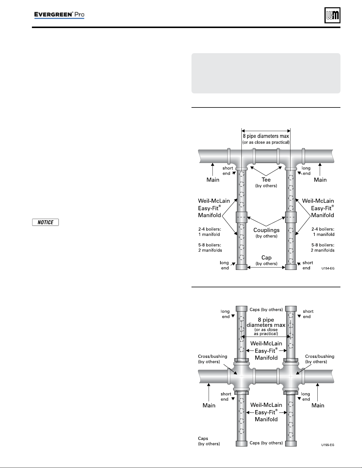
Maximum connected load per manifold:
2-inch manifold — 450 MBH
3-inch manifold — 1400 MBH
4-inch manifold — 2900 MBH
Figure 5 Single-sided EZ-Fit Header connection
Figure 6 Double-sided EZ-Fit Header connection
Multiple boiler installations
(continued)
Easy-Fit
®
piping installation
1. Main header and Easy-Fit® Manifold pipe sizing.
a. Size system piping as required for the fl ow.
b. Install tees on the system piping for Easy-Fit® manifolds
as shown in Figure 5 or Figure 6 . Size manifolds to handle
total connected boiler output as shown.
2. Provide connections in main header for Easy-Fit® manifolds
as close as possible to the midpoint of multiple boilers.
a. Use tees for four or less boilers, as in Figure 5 .
b. Use either tees ( Figure 5 ) or crosses ( Figure 6 ) for fi ve
or more boilers.
3. Manifold placement:
a. To alternate spacing for supply and return lines to boilers,
reverse the short-end and long-end of the manifolds as
shown in Figure 5 and Figure 6 .
b. Return manifold must be on the return side of the main
and supply manifold must be on the supply side of the
main. Drawings in this manual show fl ow in system main
from right to left. For system fl owing left to right, reverse
the locations of the manifolds accordingly.
4. Connect from Easy-Fit® manifold branches to boiler supply
and return connections using copper or steel pipe, sized for
the required fl ow rate.
It is recommended to pipe to boilers such
that the fi rst boiler connection off the return
manifold is piped to the furthest connection
on the supply manifold from the main header.
See Figure 8, page 14 and Figure 10, page 18 for
example.
5. Install an isolation valve on the supply and return of each
boiler as shown in the piping diagrams in this manual. Some
local codes may require the use of individual water level
controls and limits on each boiler because isolation valves
are installed.
6. Install main system air eliminator and primary circulator in
supply piping as shown in piping diagrams. Place expansion
tank on suction side of system circulator as shown.
7. Install system accessories as shown in drawings.
8. Piping recommendation drawings:
a. Figure 5 and Figure 6 show details of Easy-Fit® manifolds.
b. Figure 7, page 8 is a schematic piping drawing showing
the locations of typical boiler piping and system piping,
including limits and other devices often required by lo-
cal codes.
c. Figure 8, page 14 and Figure 10, page 18 are three di-
mensional piping drawings of typical multiple boiler
installation.
d. Figure 12, page 22 shows recommend piping when an
isolating heat exchanger is needed.
If desired, other primary/secondary piping arrangements
can be used.
Part number 550-100-214/1220
– 8 –
CONDENSING GAS BOILER — 110/155 Advanced Manual
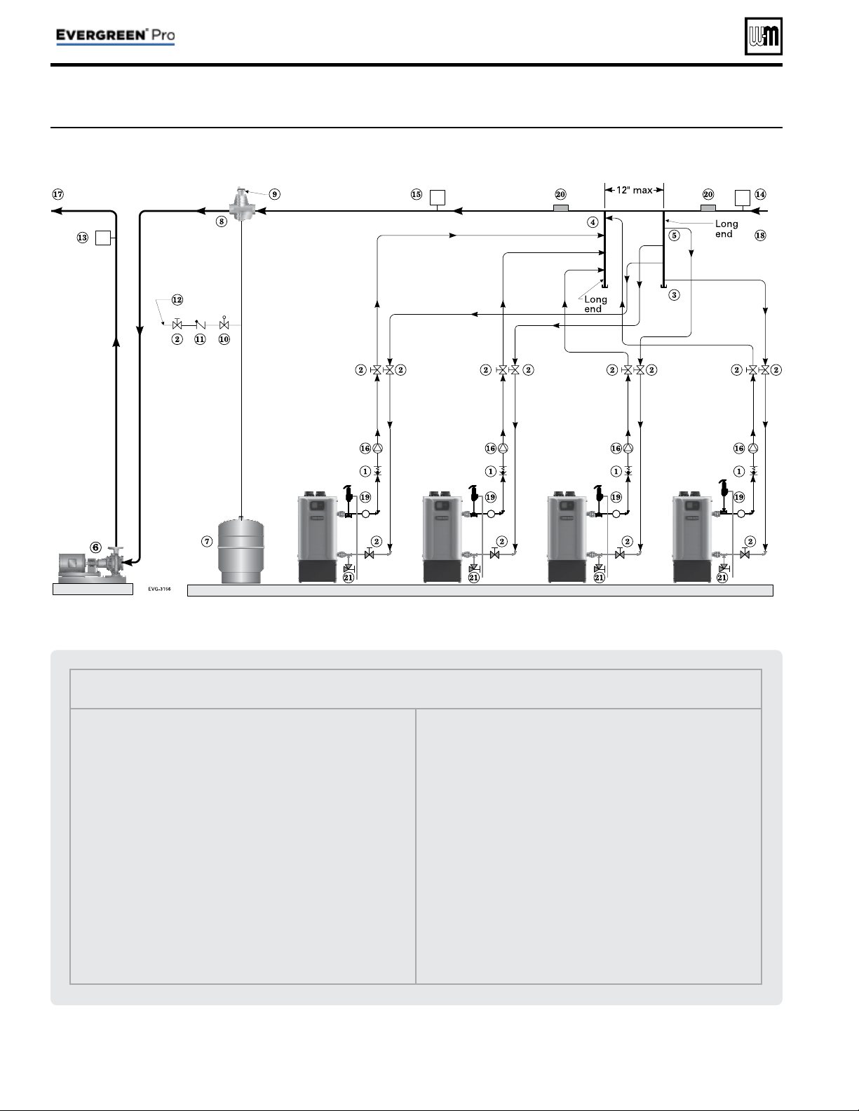
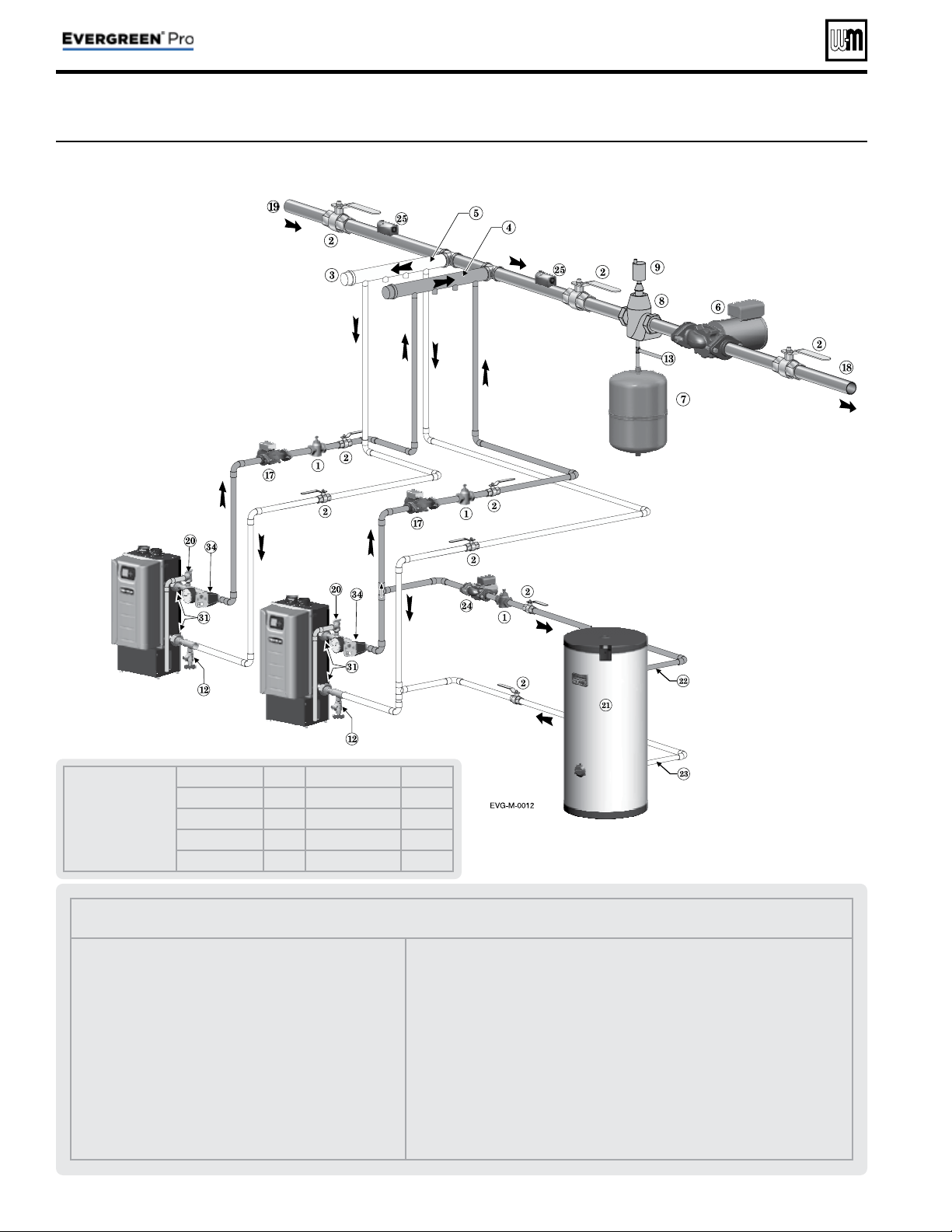
Legend — Figure 7
1 Flow/check or spring check valve.
2 Isolation valves.
3 Cap.
4 Easy-Fit® Manifold (supply) — layout and size per page 7 .
5 Easy-Fit® Manifold (return) — layout and size per page 7 .
6 Primary circulator.
7 Expansion tank (diaphragm type).
8 System air eliminator.
9 System automatic air vent.
10 Pressure reducing valve.
11 Check valve or backfl ow preventer, as required by applicable codes.
12 Cold water supply.
13 Supply water temperature control (when used).
14 Low water cutoff (when used) (place above primary header).
15 Water fl ow switch (when used) — locate a fl ow switch in each
boiler loop if individual protection is required.
16 Boiler circulator.
17 System supply.
18 System return.
19 Boiler P/T gauge, relief valve and discharge piping, installed per
Evergreen
®
boiler manual.
20 Strap system supply and return sensors to lines as shown, at least 6
pipe diameters (but no more than 3 feet) from boiler connection
tees.
21 Boiler drain valves.
Figure 7 Piping schematic — typical piping for multiple Evergreen
®
boilers, using Weil-McLain Easy-Fit manifolds
(adjust boiler connections as required for other boiler models)
Multiple boiler installations
(continued)

Fast-Track Setup — Requirements by Boiler
Part number 550-100-214/1220
– 9 –
CONDENSING GAS BOILER — 110/155 Advanced Manual
Fast-Track Setup
Evergreen
®
control Fast-Track Setup takes advantage of the
control WIZARD to provide the shortest possible method to set
up the control.
Perform the
Fast-Track Setup steps on page 10 to ensure the
minimum adjustments needed for ADVANCED mode control
operation are completed.
The remainder of this manual provides detailed information
about control setup and operation available for fi ne tuning,
troubleshooting and custom setup applications.
Temperature settings — You must ensure
that the Evergreen® control is set for the
proper water temperatures for the system.
Excessive water temperature can cause signifi -
cant property damage in some applications.
Multi-temperature systems — If the
heating system includes circuits that require
lower temperature water (radiant slab circuits,
for example) as well as higher temperature
circuits (DHW, fi nned tube baseboard, etc.),
it is recommended to protect low-temperature
circuits with limit controls that are wired to
an Evergreen® control external limit circuit.
Failure to provide regulation can result in
substantial property damage.
Setup for single boilers
For single boilers not operated as part of an network, follow the
single-boiler setup procedures in the Evergreen® boiler manual.
Using an external multiple boiler controller —
Remote modulation using an external controller
only works with each boiler set up as a SINGLE
boiler in the EVG Control setup. Follow instruc-
tions in this manual to setup the control using
ADVANCED mode.
Multiple boiler networks
Multiple boiler networks are confi gured with a MASTER boiler
and one or more SHADOW boilers. (See above for applications
using external controller.)
• The
MASTER boiler control regulates the fi ring of all boilers
when providing heat to the system zones.
•
SHADOW boilers respond to heat demand from the master
control except when operating for local (direct-connected)
heat calls.
Priorities
The Evergreen® control allows assigning multiple priorities.
These priorities will be given preference in the order below:
• Multiple boilers: LOCAL PRIORITY 1, NETWORK PRIOR-
ITY 1, NETWORK PRIORITY 2, LOCAL PRIORITY 2.
• Single boilers: PRIORITY 1, PRIORITY 2, PRIORITY 3.
DHW circuit in system — For high-demand
DHW circuits, the control setting for MIN
BOILERS must be set using the NETWORK 1
or NETWORK 2 priority menu after the WIZ-
ARD is completed to ensure quick response to
demand. See page 53 for a description of the
MIN BOILERS setting.
Timings
Timing settings regulate boiler sequencing and ensure mini-
mum and maximum operating times for heating calls on each
system. Timings can be adjusted during the Wizard setup or
manually, as explained elsewhere in this manual.
Also see page 49 for additional information on control timings
and rotation and sequencing methods.
NET MIN ON TIME (multiple boilers only)
• This parameter is available during the Wizard or manually
in the NETWORK SETTINGS menu ( Figure 24, page 48 ).
• When a boiler is being called on by the master boiler to
satisfy a
network demand, the boiler will fi re for at least
as long as the MIN TIME ON NET before it switches to
satisfy a Local Priority if one is active.
• This timing avoids short cycling due to changes in de-
mand.
MIN ON TIME
• This parameter is available during the Wizard or manually
in the PRIORITY SETTINGS menu ( Figure 29, page 54 ).
• When the boiler is being called on to satisfy a higher prior-
ity, the boiler will fi re for at least as long as the MIN ON
TIME before it switches to satisfy that priority.
• This timing avoids short cycling due to changes in de-
mand.
NET MAX ON TIME (multiple boilers only)
• This parameter is available during the Wizard or manually
in the NETWORK SETTINGS menu ( Figure 24, page 48 ).
• When a boiler is being called on by the master boiler to
satisfy a
network demand, the boiler will fi re for no longer
than the MAX TIME ON NET before it switches to satisfy
a Local Priority if one is active.
• This timing avoids a long-duration call from preventing
other demands from being met for too long a duration.
MAX ON TIME
• This parameter is available during the Wizard or manually
in the PRIORITY SETTINGS menu ( Figure 29, page 54 ).
• When a boiler is being called on by to satisfy a lower pri-
ority, the boiler will fi re for no longer than the MAX ON
TIME before it switches to satisfy that priority.
• This timing avoids a long-duration call from preventing
other demands from being met for too long a duration.
Fast-Track Setup — Steps
The WIZARD must be used when using the Fast-Track Setup procedure. This is necessary to ensure that all required settings
are made. In addition, all instructions in the
Evergreen® boiler manual must be followed completely. Failure to comply could
result in severe personal injury, death or substantial property damage.
Step 1
Mechanical
• Install boiler(s) per Evergreen
®
boiler manual and all
applicable codes, including vent/air piping and water
piping.
• See suggested piping in this manual and boiler manual.
Each boiler must be connected with primary/secondary
piping and supplied with a boiler circulator.
• As shown in the suggested piping examples, DHW tanks
can be either piped directly off of individual boilers or as a
separate zone in the heating system.
• See page 6 for additional information on multiple boiler
installation options.
Step 2
Electrical
For details, see FIELD WIRING information beginning on
page 26 .
BOILER POWER SUPPLY
• Connect minimum 120 VAC power to boiler as directed on
the boiler wiring diagram (on boiler and on page 34 ).
INPUTS & OUTPUTS
• Each boiler provides three input/output pairs. Input circuits
are 24 VAC. DO NOT apply voltage. Use dry contacts only.
Outputs are 120 VAC, 2.2-amps max (use relays if loads
exceed 2.2 amps or if outputs must be 24 VAC or must be
isolated contacts).
• The input/outputs can be used with zone thermostats and
zone circulators or zone valves (requires isolation relays
unless valves are 120 VAC), providing up to three zones per
boiler on a multiple system.
• Each boiler also provides a 120 VAC output for its boiler
circulator. Use a relay if circulator requires for than 2.0 amps.
• If required, the AUX/PUMP OUTPUT feature can turn any
of the input/outputs into a customizable output with many
operation types. This should be used for system pumps
which operate independently from a heat demand or when
multiple inputs should activate a common output. Setup
can be done through the WIZARD or manually in ASSIGN
INPUTS menu.
SENSORS
• Connect an outdoor sensor, system supply sensor and
system return sensor to at least one of the boilers in a
multiple boiler system..
• Preferably, connect outdoor, system supply and system return
sensors to more than one boiler to provide redundancy. If
one of the sensors fails, the master boiler Evergreen
®
control
automatically looks for an available sensor.
MULTIPLE BOILER COMM CABLES
• For multiple boilers, connect boiler-to-boiler communication
cables as directed on page 33 .
ADDITIONAL INFORMATION
• For fl ow switch or CAD interlock wiring, see page 33 .
• For external limit connections, see page 30 .
• For low water cut-off connections, see page 30 .
• For 0–10VDC inputs, see page 31 .
ZONING METHODS
• See wiring and control setup information for typical zoning
applications beginning on page 36 .
• See example systems beginning on page 14 .
Step 3
POWER ON
Follow all instructions in the Evergreen®
boiler manual, including all pre-start-up
inspections and fi nal checks.
• Turn OFF the manual gas cock at the boiler to prevent gas
fl ow during setup.
• Turn the boiler ON/OFF switch to ON.
• Follow the prompts on the screen to reach the BOILER
SETTINGS initial start-up screen.
• See Figure 17, page 40 for navigation information. Note that
the screen sequence changes after initial setup, as shown.
Step 4
WIZARD
• Select the START WIZARD option from the
initial screen BOILER SETTINGS menu (see
Figure 17, page 40 ).
• Use on-screen help as needed. For additional information,
see details in this manual.
• DO NOT select SKIP WIZARD unless the control is
to be confi gured manually.
SINGLE BOILERS — Set up the control
following instructions in the Evergreen
boiler manual. If ADVANCED settings
are required, change to ADVANCED
mode from the CONTRACTOR menu.
See ADVANCED mode setup information
elsewhere in this manual.
Step 5
Finish setup
• Some additional control settings may need to be changed,
depending on the application.
• See explanation of Evergreen
®
control operation and
settings, beginning on page 41 .
• For high-demand loads requiring fast
response, such as network DHW, access the
NETWORK PRIORITY screen for the assigned priority (see
Figure 28, page 52 ). Change the MIN BOILERS to the
number of boilers needed for peak load.
Step 6
Start-up
• Apply the Evergreen
®
boiler manual instructions to verify
the installation and to start up the boiler, using combustion
test instruments as directed.
Part number 550-100-214/1220
– 10 –
CONDENSING GAS BOILER — 110/155 Advanced Manual
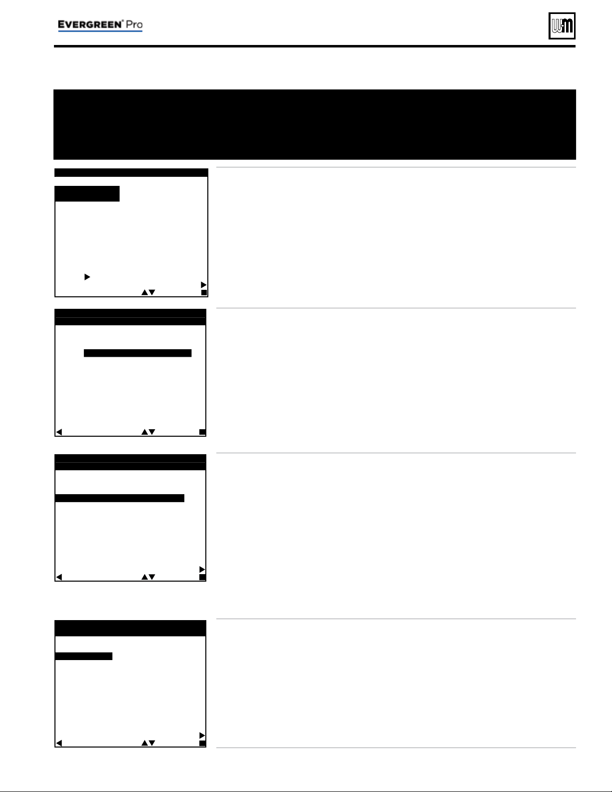
Fast-Track Setup — The WIZARD
B O I L E R S E T T I N G S
h
H I G H
A L T I T U D E :
N O
WW S D T E M P : # # # º F
F U E L T Y P E :
N A T U R A L G A S
L I Q U I D P R O P A N E
S T A R T W I Z A R D
S K I P W I Z A R D
F O R D E T A I L S O N A N Y
S E L E C T E D L I N E , P R E S S
T H E
B U T T O N .
H E L P
S E L E C T E D I T
• This screen appears on initial start-up.
• Perform the
WIZARD steps for every boiler.
•
HIGH ALTITUDE and FUEL TYPE are critical
parameters. They must be entered correctly for
each boiler before proceeding.
• Enter the
WWSD temperature — This sets the
outside temperature below which space heat-
ing systems will be disabled.
WWSD must also
be selected during system setup to enable it.
• Select
START WIZARD.
•
DO NOT select SKIP WIZARD. Selecting SKIP
WIZARD will take the screen to the USER
MENU. All setup would then have to be done
manually.
•
NOTICE — Once SKIP WIZARD has been
selected, the WIZARD will no longer be
available unless the control is set to FACTORY
DEFAULT and control start-up is begun again.
E V E R G R E E N W I Z A R D
# # O F # #
W H A T I S T H E U S E O F
I N P U T / O U T P U T - # ?
H E A T / D H W D E M A N D
A U X / P U M P O U T P U T
N O T U S E D
N O T E :
1 2 0 V O U T P U T S H A V E A
2 . 2 A M P L I M I T . I F M O R E
C U R R E N T I S R E Q U I R E D ,
U S E A N E X T E R N A L
C O N T A C T .
B A C K S E L E C T N E X T
• Each boiler provides three input/output pairs.
Each pair can be setup to function as a call for
heat with output or to perform an auxiliary
function, such as operating a system pump.
• After the WIZARD screens are completed for
INPUT 1, the WIZARD starts over with INPUT/
OUTPUT 2, then to INPUT/OUTPUT 3 after 2
is completed.
• Select
HEAT/DHW DEMAND if the input/out-
put is connected to a heating or DHW zone or
system. The input could be a zone thermostat
or end switch. The output could be 120 VAC to
a circulator (2.0 amps or less) or isolation relay.
• Select
AUX PUMP/ OUTPUT if the input is to
be used for a system pump, combustion air
damper interlock, etc.
• To operate a
system pump, setup the input
as
AUX PUMP/OUTPUT. Connect the cor-
responding output to the system pump or
pump relay (if pump load exceeds 2.0 amps).
When the
ACTIVATE OUTPUT # screen ap-
pears, select
ANY INPUT BY ITS PRIORITY
SETTINGS as the operating mode.
• Select
NOT USED if the input/output is not
needed.
E V E R G R E E N W I Z A R D
# # O F # #
W H A T P R I O R I T Y I S
I N P U T / O U T P U T - # ?
P R I O R I T Y 1 - L O C A L 1
P R I O R I T Y 2 - N E T W O R K 1
P R I O R I T Y 3 - N E T W O R K 2
P R I O R I T Y 4 - L O C A L 2
H E L P
B A C K S E L E C T N E X T
• For multiple boiler applications, the Evergreen
®
control provides up to four priorities, as listed
on this screen. Preference is given to these
priorities in the order shown (Priority 1
through 4).
• Select which priority will be operated by this
input/output.
• All boilers can operate on demand from
Net-
work priorities.
• NETWORK PRIORITIES
– Any input on any boiler can be assigned to a
network priority (NETWORK PRIORITY 1
or NETWORK PRIORITY 2).
– The WIZARD will only allow setting up a
Network Priority on the Master boiler. It
will skip setting up a Network Priority on
all shadow boilers.
– All boilers on the network will fi re to meet net-
work demands
• LOCAL PRIORITIES
– Any boiler can use its input/outputs to
operate up to two local priorities (LOCAL
PRIORITY 1 and LOCAL PRIORITY 2).
This applies only for heating loops directly
piped to the boiler.
– Local demands are only satisfied by the
boiler to which the input is wired. Local
heating loops must be directly piped to
the boiler.
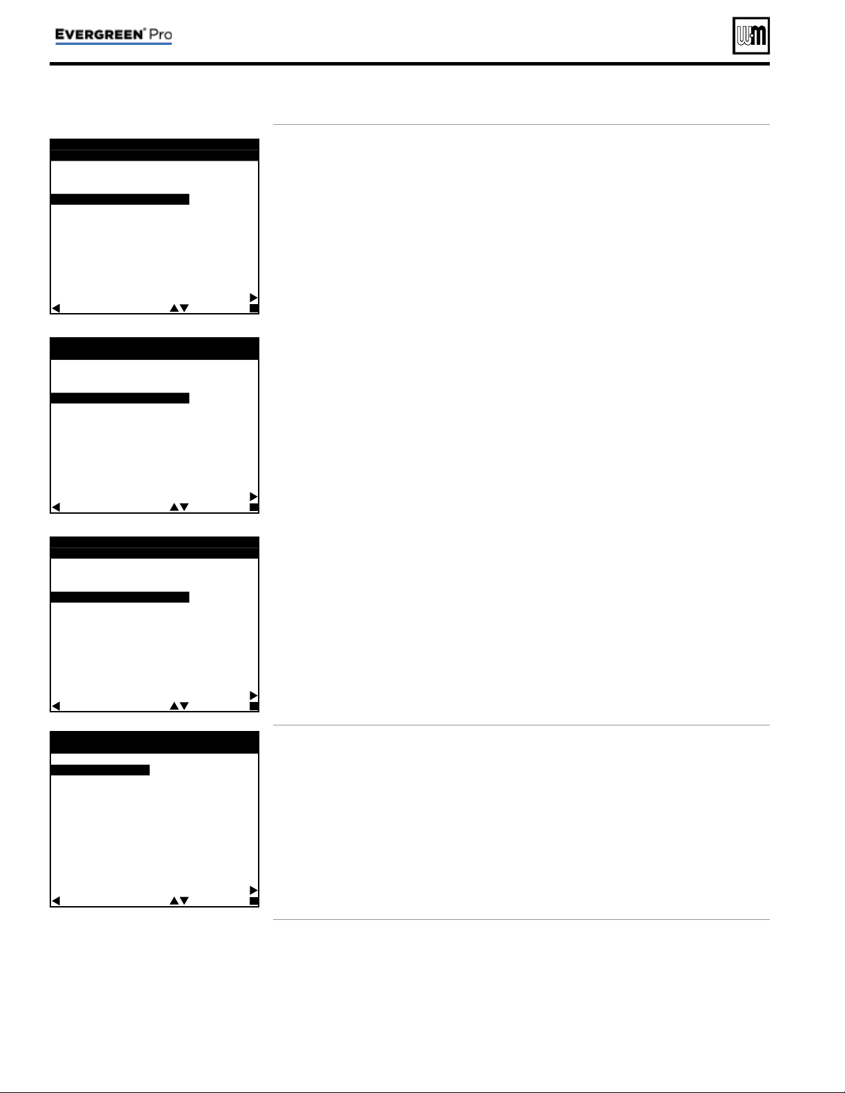
E V E R G R E E N W I Z A R D
# # O F # #
W H A T S Y S T E M T Y P E I S
P I P E D T O O U T P U T - # ?
F A N C O I L
F I N N E D T U B E B A S E B O A R D
C A S T I R O N B A S E B O A R D
C A S T I R O N R A D I A T O R
R A D I A N T - S L A B O N G R A D E
R A D I A N T - T H I N S L A B
R A D I A N T - B E L O W F L O O R
R A D I A N T - A B O V E F L O O R
D H W
C U S T O M - # # # # # # # #
H E L P
B A C K S E L E C T N E X T
• Use this screen to select the system type for
this priority.
• The control will automatically set operating
parameters to suit the system type chosen.
• To see factory default settings for each system,
see Figure 21, page 45 .
• Operating parameters can be customized in
the next screen, if desired.
• Select
CUSTOM to manually confi gure the
operating settings for the system.
•
NETWORK PRIORITY 1 or 2 — This screen
will not show on a shadow boiler if the input/
output is assigned to a network priority. The
screen will only appear on the Master boiler,
where the priority must be confi gured.
• The WIZARD is available only on initial setup of the boiler.
It cannot be accessed later. If the WIZARD is accidentally
by-passed, follow navigation sequences shown on page 46
and page 47 . Select RESET FACTORY DEFAULTS on the
Boiler Settings menu. Follow screen directions. Boiler setup
must then be started over from the beginning.
• The WIZARD leads
through a step-by-step
setup procedure designed
for the application chosen.
• Context-sensitive help
is available to explain
the purpose of key setup
items.
Part number 550-100-214/1220
– 11 –
CONDENSING GAS BOILER — 110/155 Advanced Manual
Fast-Track Setup — The WIZARD (continued)
If TARGET ADJUST = ODT
E V E R G R E E N W I Z A R D
# # O F # #
S Y S T E M T Y P E : # # # # # # # #
T A R G E T M O D S E N S O R :
B O I L E R O U T
T A R G E T A
D
J U S T :
O
D
T
S U P P
L Y M A X : # # # °
F
S U P P L Y M I N : # # # ° F
O D R E S E T M A X : # # # ° F
O D R E S E T M I N : # # # ° F
B O O S T T I M E : # # # M I N
R U N B O I L E R P U M P ? Y E S
R U N A U X / P U M P O U T ? Y E S
M A X O N T I M E : # # M I N
H E L P
B A C K S E L E C T N E X T
If TARGET ADJUST = 0–10V
E V E R G R E E N W I Z A R D
# # O F # #
S Y S T E M T Y P E : # # # # # # # #
T A R G E T M O D S E N S O R :
B O I L E R O U T
T A R G E T A
D
J U S T :
0
-
1
0
V
S U P P
L Y M A X : # # # °
F
S U P P L Y M I N : # # # ° F
V O L T S F O R M A X : # # # ° V
V O L T S F O R M I N : # # # ° V
B O O S T T I M E : # # # M I N
R U N B O I L E R P U M P ? Y E S
R U N A U X / P U M P O U T ? Y E S
M A X O N T I M E : # # M I N
H E L P
B A C K S E L E C T N E X T
If TARGET ADJUST = NONE
E V E R G R E E N W I Z A R D
# # O F # #
S Y S T E M T Y P E : # # # # # # # #
T A R G E T M O D S E N S O R :
B O I L E R O U T
T A R G E T A D J U S T : N O N E
S U P P L Y M A X : # # # ° F
R U N B O I L E R P U M P ? Y E S
R U N A U X / P U M P O U T ? Y E S
M A X O N T I M E : # # M I N
H E L P
B A C K S E L E C T N E X T
E
V E R G R E E N W I Z A R D
# # O F # #
A C T I V A T E O U T P U T - # :
- A L W A Y S O N
- E X T
E
R N A L S W I T C H
- O U T D O O R B E L O W W W S D
- A N Y I N P U T
- A N Y I N P U T B Y I T S
P R I O R I T Y S E T T I N G S
- A N Y B U R N E R D E M A N D
H E L P
B A C K S E L E C T N E X T
• Use this screen to set when a SYSTEM
PUMP/AUX output is activated. For detailed
explanation, see Figure 31, page 57 and Fig-
ure 32, page 57 .
•
SYSTEM TYPE – Read only (assigned in
previous step).
•
TARGET MOD SENSOR – Read only for
network boilers, adjustable for single boil-
ers – Shows which sensor reading is used for
modulation. Boiler sensor is default for local
priorities. System sensor is default for network
priorities.
•
TARGET ADJUST – Select how target tem-
perature is calculated —
NONE (no reset, fi xed target temperature =
SUPPLY MAX)
ODT (outdoor reset operation; default setting).
Target temperature is calculated from the
outdoor reset curve. SUPPLY MAX is target
temperature when outside temperature equals
OD RESET MAX. SUPPLY MIN is target
temperature when outside temperature equals
OD RESET MIN. At outdoor temperatures in
between, target temperature is scaled propor-
tionally. See Figure 1, page 5 for details.
0–10V (target temperature based on input
from remote source). SUPPLY MAX is target
temperature at VOLTS FOR MAX value. SUP-
PLY MIN is target temperature at VOLTS FOR
MIN value. For voltage values between max
and min, target temperature is scaled propor-
tionally. See Figure 2, page 5 for details.
•
SUPPLY MAX – Set SUPPLY MAX to the
required supply water temperature for the
system at design maximum heat loss (typi-
cally 180°F for fi nned tube baseboard on new
installations.)
•
SUPPLY MIN – SUPPLY MIN should equal the
desired minimum supply water temperature
for the system. This line will not show if Target
Adjust is selected as NONE.
•
OD RESET MAX – means the outdoor temper-
ature at which the target temperature reaches
its minimum (SUPPLY MIN). (Does not ap-
pear if 0–10V is selected for Target Adjust.)
•
OD RESET MIN – means the outdoor tempera-
ture at which the target temperature reaches its
maximum value (SUPPLY MAX). (Does not
appear if 0–10V is selected for Target Adjust.)
•
VOLTS FOR MAX – Appears if 0–10V is
selected for Target Adjust. Set the voltage at
which SUPPLY MAX temperature is required.
•
VOLTS FOR MIN – Appears if 0–10V is selected
for TARGET ADJUST. Set the voltage at which
SUPPLY MIN temperature is required. For
voltages between Min and Max, the target
temperature will be adjusted on a linear curve.
•
BOOST TIME – Every time the call for heat
surpasses this duration of time the target
temp will boost up 10°F. It will cap off at
Supply Max.
•
RUN BOILER PUMP – Selects whether the
Boiler Pump is turned on while running on
this call for heat. This setting is YES for net-
work priorities and is not adjustable.
•
RUN AUX PUMP/ OUT – Selects whether In-
puts/Outputs in the system confi gured as AUX
PUMP/OUTPUT are turned on while running
on this call for heat.
•
MAX ON TIME / MIN ON TIME – Maximum or
minimum time the network will run on this
priority if it is being asked to run on another
network priority. MAX shows for Network
Priority 1, MIN shows for Network Priority 2.
This line ONLY shows on the Master boiler
Wizard. It does not appear on Shadow boilers.
Part number 550-100-214/1220
– 12 –
CONDENSING GAS BOILER — 110/155 Advanced Manual
Fast-Track Setup — The WIZARD (continued)
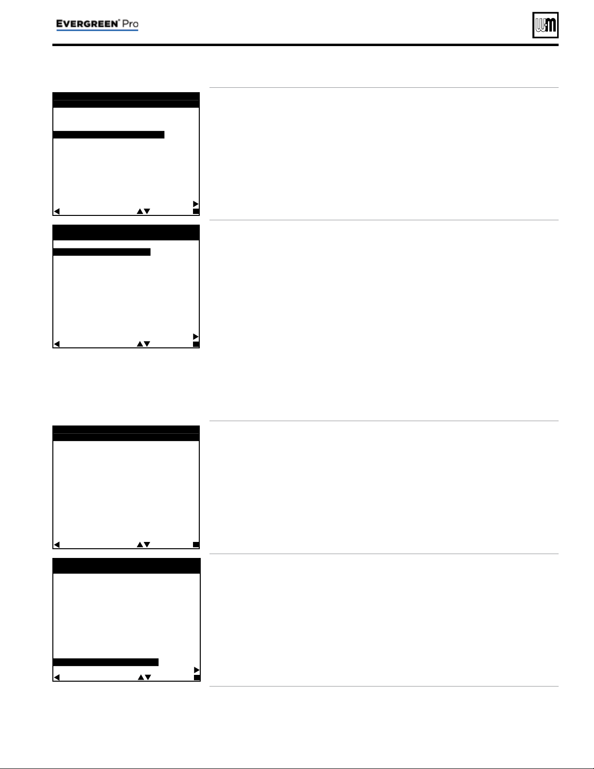
E V E R G R E E N W I Z A R D
# # O F # #
L O C A L
▼
-
▼
N E T W O R K
S W I T C H I N G T I M E S
L P 1 M A X O N T I M E : # # # M
|
▼
▼
|
N E T M I N O N T I M E : # # # M
N E T M A X O N T I M E : # # # M
|
▼
▼
|
L P 2 M I N O N T I M E : # # # M
N E X T S T E P H E L P
B A C K S E L E C T E D I T
• The timings set on this screen prevent the boiler
from operating too long on one demand if
another demand is present. They also prevent
short cycling on a demand.
• LP1 and LP2 are times for local priorities.
• MIN NET ON TIME and MAX NET ON TIME
are the maximum and minimum times this
boiler will dedicate to a call from a network
demand.
E V E R G R E E N W I Z A R D
# # O F # #
B O I L E R S E Q U E N C I N G
S E Q U E N C E T Y P E :
S M A R T
B A S E R A T E H I G H : # # # %
B A S E R A T E L O W : # # # %
L E A D B O I L E R R O T A T E :
I N C R E M E N T A L H O U R S
R O T A T E F R E Q : # # D A Y S
F O R C E L E A D R O T A T E : Y E S
N E X T S T E P
H E L P
B A C K S E L E C T N E X T
• Use this screen to set how boilers are sequenced
and how usage is rotated between boilers on
the network.
• For a complete explanation of sequencing and
rotation, see page 49 and page 50 .
• Sequencing means the way in which boiler
fi ring rate is controlled as boilers are turned on
and off by the master boiler.
– Three SEQUENCE TYPES are available:
SERIES sequencing allows each boiler to
reach full input before bringing on the next
boiler in sequence. PARALLEL sequencing
uses a limiter, called BASERATE HIGH, to
limit the fi ring rate before adding additional
boilers. SMART sequencing (factory default
setting) uses a low fi ring rate setting, called
BASERATE LOW, to keep boilers at a low
fi ring rate, bringing on additional boilers at
reduced rate until all boilers are on if neces-
sary. Boilers are then allowed to modulate to-
gether as high as necessary to meet demand.
• Rotation means how and how often the boiler
fi ring order is changed.
– LEAD BOILER ROTATE options are
based on how long a boiler has operated. Se-
lect either OFF, BY BOILER ID, TOTAL
HOURS or INCREMENTAL HOURS.
See detailed explanation of options on
page 49 .
– Use the ROTATE FREQ setting to control
how often the rotation sequence is changed.
– FORCE LEAD ROTATE – If set to YES,
then when the frequency timer expires and
the new order is calculated, this forces the
new boiler order to take effect while a heat
demand is currently active.
E V E R G R E E N W I Z A R D
# # O F # #
S E T D A T E & T I M E
T I M E : H H : M M A M
D A T E : M M / D D / Y Y
B A C K S E L E C T N E X T
• This screen appears ONLY on the master boiler,
not on shadow boilers.
• Set the time and date to ensure that control
logs accurately record time/date of occurrences.
• Time and date information is provided to the
shadow boilers by the master boiler.
E V E R G R E E N W I Z A R D
# # O F # #
M A I N T E N A N C E I N F O
N A M E : # # # # # # # # # # # # # # # #
P H O N E : # # # - # # # - # # # #
M O D E L : # # # # # # # # # # - # #
C P # : # # # # # # # # # #
I N S T A L L E D : D D / M M / Y Y
L A S T D A T E : D D / M M / Y Y
N E X T D A T E : D D / M M / Y Y
I N T E R V A L S E T : 1 2 M O N T H S
W I Z A R D C O M P L E T E
H E L P
B A C K S E L E C T N E X T
• Use this screen to enter relevant data about the
installer and boiler.
• See Figure 33, page 58 for full explanation of
the inputs on this menu.
Part number 550-100-214/1220
– 13 –
CONDENSING GAS BOILER — 110/155 Advanced Manual
Part number 550-100-214/1220
– 14 –
CONDENSING GAS BOILER — 110/155 Advanced Manual
Blr 1
Blr 2
Fast-Track Setup — Typical Application A
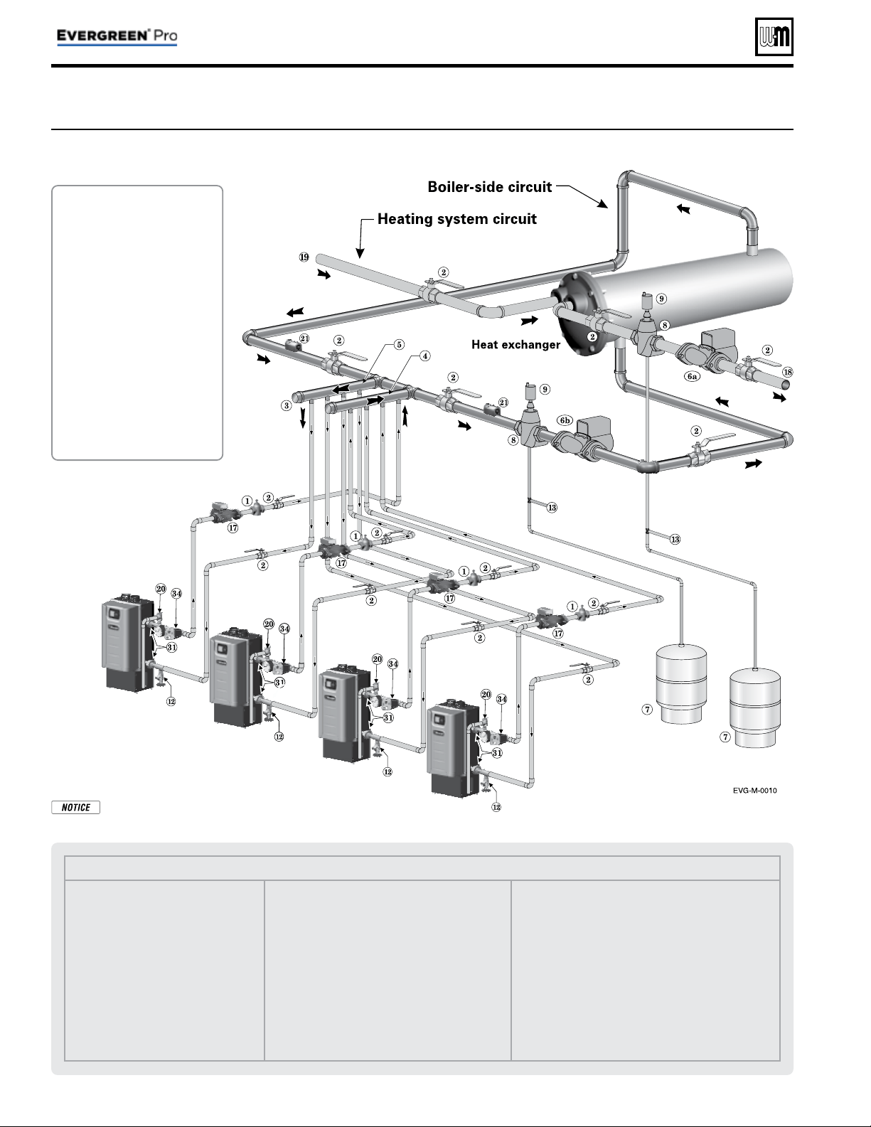
Figure 8 Typical Application A — Piping layout — typical piping for multiple Evergreen
®
boilers, using Weil-McLain
Easy-Fit manifolds (2-boiler system) (adjust boiler connections as required for other boiler models)
Legend — Figure 9
1 Flow/check or spring check valve.
2 Isolation valves (when used).
3 Caps.
4 Easy-Fit® Manifold (supply) — layout and size per page 7 .
5 Easy-Fit® Manifold (return) — layout and size per page 7 .
6 System circulator. (not used if system is circulator zoned)
7 Expansion tank (diaphragm type).
8 System air eliminator.
9 System automatic air vent.
12 Boiler drain valves.
13 Cold water supply (per applicable codes).
17 Boiler circulator — circulates water between boiler and
Easy-Fit® Manifolds.
18 System supply.
19 System return.
20 Boiler relief valve and discharge piping, installed per Evergreen
®
boiler manual.
21 Indirect-fi red storage water heaters (Weil-McLain Aqua Plus Line shown) —
Example is shown connected to one boiler of the system. Setup is shown on the
next page for this confi guration and also for the option of a DHW tank installed as
a system zone.
22 DHW boiler water supply, typical.
23 DHW boiler water return, typical.
24 DHW boiler-side circulator and fl ow/check valve.
25 Strap system supply and return sensors to lines as shown, at least 6 pipe diameters
(but no more than 3 feet) from boiler connection tees. For redundancy, you can
install a supply and return sensor connected to each boiler.
31 Unions.
34 Low water cutoff.
Suggested DHW
boiler-side pipe
sizing
(for max 0.04
feet head loss per foot of
total equivalent length,
TEL)
Flow rate Size Flow rate Size
1 – 3.9 gpm ¾ 24 – 45 gpm 2
3.9 – 7.1 gpm 1 45 – 75 gpm 2½
7.1 – 16 gpm 1¼ 75 - 140 gpm 3
16 – 24 gpm 1½ 140 – 290 gpm 4
See
Figure 9, page 16
for setting up
an alternate
confi guration if
DHW is located
in the system as
a zone instead
of being directly
connected.
NOTICE:
This method does
not provided
DHW redundancy.
DHW can only
be supplied
when Boiler 2 is
operational.
Part number 550-100-214/1220
– 15 –
CONDENSING GAS BOILER — 110/155 Advanced Manual
Fast-Track Setup — Typical Application A (cont.)
Purpose
• Space heating with multiple zones using system pump
or zone circulators.
• Zoning with circulators or zone valves.
• DHW piped directly to the Shadow 2 boiler.
• DHW priority — space heating is discontinued dur-
ing call for heat from water heater.
Control setting notes
• See the table on page 16 for required and optional
settings.
• The table follows the general setup required to achieve
the shown systems with shown priorities.
• Settings can be made using the WIZARD or by fol-
lowing instructions elsewhere in this manual to enter
the settings manually.
Circulators and piping
Provide an external relay and external power to any
circulator if its load rating exceeds 2.2 amps FLA,
3.6 amps locked rotor, or 16.4 amps in rush.
• Piping must be primary/secondary as shown.
• DHW circulator must be selected to handle the pres-
sure drop through the boiler, water heater and piping.
DHW circulator supplied by installer.
• For some large indirect water heaters, the required
fl ow rate may require piping the water heater dif-
ferently.
• The control settings in table at right provide DHW priority
— space heating will be discontinued during a call for DHW.
• Zone circulators and relays supplied by installer. For alternate
zone wiring using a zone controller, see page 36 .
BOILER
• Boiler circulator shipped loose with boiler.
• Follow all instructions in this manual for piping boiler and
system.
*
= Supplied by installer
1 DHW circulators *
2 BOILER circulators
(shipped loose with boiler)
3 Zone circulators *
4 Zone valves (120V shown) *
5 120VAC power supply, 15-amp
minimum rating
6 Control
7 Zone thermostats *
8 Supply temperature sensor —
strap to supply line
9 Return temperature sensor —
strap to return line
10 DHW tank aquastats *
11 Outdoor temperature sensor
(supplied with boiler; install if
Control will be set for outdoor
reset operation)
12 Low water cutoff
13 Comm Board
14 System circulators and relay*
page 19
15 Shell-side circulators * page 23
LEGEND for Applications A, B and C
Part number 550-100-214/1220
– 16 –
CONDENSING GAS BOILER — 110/155 Advanced Manual
Fast-Track Setup — Typical Application A (cont.)
Boiler Model, Altitude and Fuel Type are critical settings. Failure to set correctly could result in severe personal
injury, death or substantial property damage.
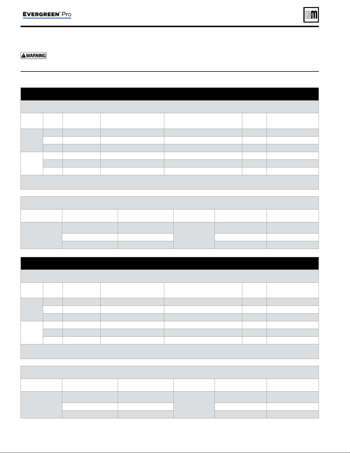
SETUP FOR Figure 8, page 14 AS SHOWN (DHW directly connected)
Boiler Wiring and Control Settings
(See Figure 8, page 14 for items referenced)
Boiler
ID
TT
input
Wired
from:
Input
Assignment
Aux
Option
Output
Wired to:
***
1
Master
1 Zone 1 Tstat Priority 2 - Network 1 N/A 1 Zone 1 Circ/Valve
2 Zone 2 Tstat Priority 2 - Network 1 N/A 2 Zone 2 Circ/Valve
3 No Wire Aux Pump/Output * Any TT Input By It's Priority Settings 3 System Circ Relay *
2
Shadow
1 DHW Aquastat Priority 1 - Local 1 N/A 1 DHW Circ.
2 Zone 3 Tstat Priority 2 - Network 1 N/A 2 Zone 3 Circ/Valve
3 Zone 4 Tstat Priority 2 - Network 1 N/A 3 Zone 4 Circ/Valve
* System circulator will not be used if system is circulator zoned. Aux Pump/Output would not be required.
An additional Zone Circ. could be used here, instead.
Priority Settings
Priority # Setting Value Priority # Setting Value
Priority 1 – Local 1
(Boiler 2 only)
System Type DHW
Priority 2 – Network 1
(Boiler 1 only)
System Type
Select heating
system type
Run Blr Pump NO Run Blr Pump YES
Run Aux Output NO Run Aux Output YES
SETUP IF DHW IS LOCATED IN SYSTEM AS A ZONE
Boiler Wiring and Control Settings
(See Figure 8, page 14 for items referenced)
Boiler
ID
TT
input
Wired
from:
Input
Assignment
Aux
Option
Output
Wired to:
***
1
Master
1 Zone 1 Tstat Priority 3 - Network 2 N/A 1 Zone 1 Circ/Valve
2 Zone 2 Tstat Priority 3 - Network 2 N/A 2 Zone 2 Circ/Valve
3 No Wire Aux Pump/Output * Any TT Input By It's Priority Settings 3 System Circ *
2
Shadow
1 DHW Aquastat Priority 2 - Network 1 N/A 1 DHW Circ/Valve
2 Zone 3 Tstat Priority 3 - Network 2 N/A 2 Zone 3 Circ/Valve
3 Zone 4 Tstat Priority 3 - Network 2 N/A 3 Zone 4 Circ/Valve
* System circulator will not be used if system is circulator zoned. Aux Pump/Output would not be required.
An additional Zone Circ. could be used here, instead.
Priority Settings
Priority # Setting Value Priority # Setting Value
Priority 2 – Network 1
System Type DHW
Priority 3 – Network 2
System Type
Select heating
system type
Run Blr Pump YES Run Blr Pump YES
Run Aux Output YES Run Aux Output YES
*** Outputs are 120 VAC maximum 2.0 amps. Use relay for other voltages or higher amperages.
Figure 9 Typical Application A — multiple boiler system — setup requirements (parameters not listed below can be
left at factory default settings unless special needs indicate different settings)

Part number 550-100-214/1220
– 17 –
CONDENSING GAS BOILER — 110/155 Advanced Manual
Notes
Part number 550-100-214/1220
– 18 –
CONDENSING GAS BOILER — 110/155 Advanced Manual
Blr 1
Blr 2
Blr 3
Blr 4
DHW1
DHW2
DHW3
Fast-Track Setup — Typical Application B
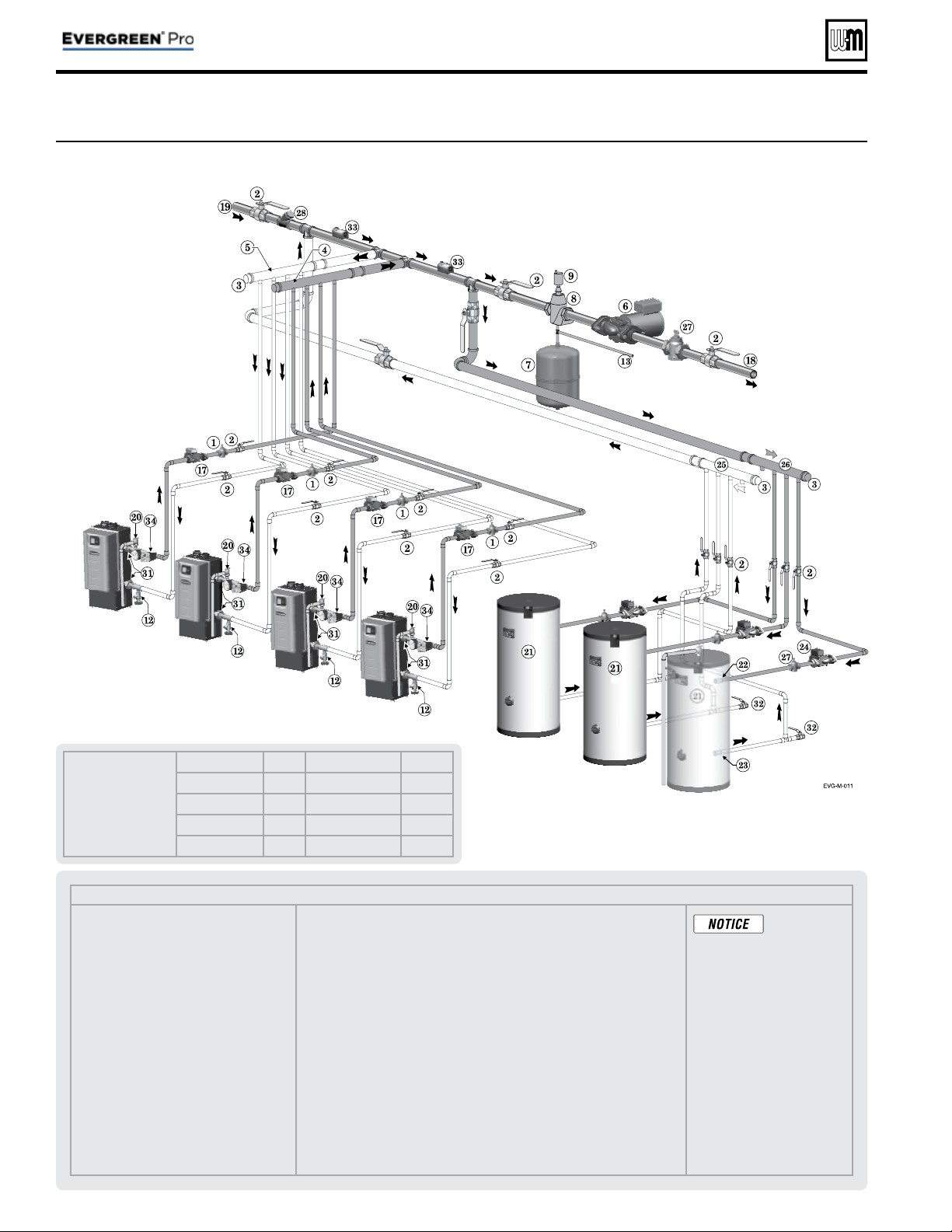
Figure 10 Typical Application B — Piping layout — typical piping for multiple Evergreen
®
boilers, with DHW storage
heaters (4-boiler system) (adjust boiler connections as required for other boiler models)
Legend — Figure 10
1 Flow/check or spring check valve.
2 Isolation valves (when used).
3 Caps.
4 Easy-Fit® Manifold (supply) — layout and
size per page 7.
5 Easy-Fit® Manifold (return) — layout and
size per page 7.
6 System circulator (not used if system is
circulator zoned).
7 Expansion tank (diaphragm type).
8 System air eliminator.
9 System automatic air vent.
12 Boiler drain valve
13 Cold water supply (per applicable codes).
17 Boiler circulator — circulates water
between boiler and Easy-Fit® Manifolds.
18 System supply.
19 System return.
20 Boiler relief valve and discharge piping,
installed per
Evergreen
®
boiler manual.
21 Indirect-fi red storage water heaters (Weil-McLain Aqua Plus Line shown) —
Example is shown with each water heater having its own circulator. Alternate:
reverse-return boiler-side piping using a single circulator.
22 DHW boiler water supply, typical.
23 DHW boiler water return, typical.
24 DHW boiler-side circulators.
25 DHW boiler-side supply Easy-Fit® Manifold.
26 DHW boiler-side return Easy-Fit® Manifold.
27 Flow/check or spring check valves (to prevent induced or gravity fl ow in heating
system or DHW piping).
28 Check valve.
29 See water heater manual for DHW piping — The boiler-side piping in this
example uses a separate circulator for each DHW tank.
31 Unions.
32 Drain valves for DHW boiler water piping.
33 Strap system supply and return sensors to lines as shown, at least 6 pipe diam-
eters (but no more than 3 feet) from boiler connection tees. For redundancy, you
can install multiple sensors, each connected to a different boiler.
34 Low water cutoff.
This piping is
suggested only.
The layout above can be controlled
with the boiler control’s multi-
boiler function, DHW priority or by
an external control that provides
multiple boiler heating and DHW
priorities. This will provide domes-
tic priority by disabling the heating
system circulator any time there is
a DHW call for heat. The boiler
circulators, item 17, must operate on
any call for heat, whether heating
system or DHW. Offset the DHW
boiler-side supply and return man-
ifolds as shown so the total run of
pipe and fi ttings to each of the water
heaters is approximately equal.
Suggested DHW
boiler-side pipe
sizing
(for max 0.04
feet head loss per foot of
total equivalent length,
TEL)
Flow rate Size Flow rate Size
1 – 3.9 gpm ¾ 24 – 45 gpm 2
3.9 – 7.1 gpm 1 45 – 75 gpm 2½
7.1 – 16 gpm 1¼ 75 - 140 gpm 3
16 – 24 gpm 1½ 140 – 290 gpm 4
Part number 550-100-214/1220
– 19 –
CONDENSING GAS BOILER — 110/155 Advanced Manual
Fast-Track Setup — Typical Application B (cont.)
See Legend on page 15 for Item number identifi cation.
Part number 550-100-214/1220
– 20 –
CONDENSING GAS BOILER — 110/155 Advanced Manual
Fast-Track Setup — Typical Application B (cont.)
Boiler Model, Altitude and Fuel Type are critical settings. Failure to set correctly could result in severe personal
injury, death or substantial property damage.
Alternate piping: DHW circuit piped elsewhere in system — If the DHW circuit is piped elsewhere in the
system, the above settings will work only if the System Pump is activated during DHW calls for heat. To set the control
for this, set PRIORITY 2 — NETWORK 1 with RUN AUX PUMP/ OUTPUT set to YES instead of NO.
Boiler Wiring and Control Settings (See Figure 10, page 18 for items referenced)
Boiler
ID
TT
input
Wired
from:
Input
Assignment
Aux
Option
Output
Wired to:
***
1
Master
1 Zone 1 Tstat Priority 3 - Network 2 N/A 2 Zone 1 Circ/Valve
2 Zone 2 Tstat Priority 3 - Network 2 N/A 3 Zone 2 Circ/Valve
3 No Wire Aux Pump/Output ** Any TT Input By It's Priority Settings 1 System Circ **
2
Shadow
1 Zone 3 Tstat Priority 3 - Network 2 N/A 1 Zone 3 Circ/Valve
2 Zone 4 Tstat Priority 3 - Network 2 N/A 2 Zone 4 Circ/Valve
3 Zone 5 Tstat Priority 3 - Network 2 N/A 3 Zone 5 Circ/Valve
3
Shadow
1 Zone 6 Tstat Priority 3 - Network 2 N/A 1 Zone 6 Circ/Valve
2 Zone 7 Tstat Priority 3 - Network 2 N/A 2 Zone 7 Circ/Valve
3 Zone 8 Tstat Priority 3 - Network 2 N/A 3 Zone 8 Circ/Valve
4
Shadow
1 DHW1 Aquastat Priority 2 - Network 1 N/A 1 DHW1 Circ
2 DHW2 Aquastat Priority 2 - Network 1 N/A 2 DHW2 Circ
3 DHW3 Aquastat Priority 2 - Network 1 N/A 3 DHW3 Circ
** System circulator will not be used if system is circulator zoned. Aux Pump/Output would not be required.
An additional Zone CIRC. could be used here, instead.
*** Outputs are 120 VAC maximum 2.0 amps. Use relay for other voltages or higher amperages.
Priority Settings
Priority # Setting Value Priority # Setting Value
Priority 2 – Network 1
System Type DHW
Priority 3 – Network 2
System Type
Select heating
system type
Run Blr Pump YES Run Blr Pump YES
Run Aux Output NO Run Aux Output YES
Min Blrs *
Select as needed for quick
response
* Min Blrs setting is accessible in the Priority menus (see Figure 24, page 48 ). It is not included in the Wizard setup options.
Figure 11 Typical Application B — multiple boiler system — setup requirements (parameters not listed below can be
left at factory default settings unless special needs indicate different settings)
Purpose
• Space heating with multiple zones using system pump or
zone pumps.
• DHW connected to primary with a secondary connection.
Multiple DHW tanks are zoned with circulators.
• DHW priority— space heating is discontinued during call
for heat from water heater(s).
Control setting notes
• See the tables in Figure 11 for required and optional
settings.
• The table follows the general setup required to achieve
the shown systems with shown priorities.
• Settings can be made using the WIZARD or by following
instructions elsewhere in this manual to enter the settings
manually.
Circulators and piping
Provide an external relay and external power to any cir-
culator if its load rating exceeds 2.2 amps FLA, 3.6 amps
locked rotor, or 16.4 amps in rush.
• Piping must be primary/secondary as shown, with the
boiler piped in a secondary loop and the DHW piped in
a secondary loop with connections spanning the boiler
connections.
• DHW circulators supplied by installer. Size circulators
for required fl ow.
• Control settings in Figure 11 provide DHW priority—
space heating is discontinued during call for DHW.
• Zone circulators and relays supplied by installer. For
alternate zone wiring using a zone controller, see page 36.

Part number 550-100-214/1220
– 21 –
CONDENSING GAS BOILER — 110/155 Advanced Manual
Notes
Part number 550-100-214/1220
– 22 –
CONDENSING GAS BOILER — 110/155 Advanced Manual
Blr 1
Blr 2
Blr 3
Blr 4
Fast-Track Setup — Typical Application C
Figure 12
Typical Application C —
Piping layout — typical piping for multiple
Evergreen
®
boilers, using isolation
exchanger (adjust boiler connections as required for other boiler models)
Legend — Figure 12
1 Flow/check or spring check valve.
2 Isolation valves (when used).
3 Cap.
4 Easy-Fit® Manifold (supply) — layout
and size per page 7 .
5 Easy-Fit® Manifold (return) — layout
and size per page 7 .
6a Heating system circulator
(exchanger tube-side).
6b Heat exchanger shell-side circulator
7 Expansion tanks (diaphragm type).
8 System air eliminator.
9 System automatic air vent.
12 Boiler drain valves.
13 Cold water supply connections (per applicable
codes).
17 Boiler circulator — circulates water between
boiler and Easy-Fit® Manifolds.
18 Heating system supply.
19 Heating system return.
20 Boiler relief valve and discharge piping,
installed per Evergreen
®
boiler manual.
21 Strap system supply and return sensors to lines
as shown, at least 6 pipe diameters (but no more
than 3 feet) from boiler connection tees. For
redundancy, you can install multiple sensors, each
connected to a different boiler.
31 Unions.
34 Low water cutoff.
Notes:
1. Contact heat exchanger manufacturer for heat ex-
changer shell-side and tube-side piping and circulator
requirements. Tube-side fl ow and temperatures must
meet heating system requirements.
2. Contact heat exchanger manufacturer for sizing heat
exchanger.
3. Heat exchanger shell-side circuit requires its own
expansion tank as shown.
4. Heating system circuit requires its own expansion
tank, as shown, plus its own relief valve set to protect
heating system and heat exchanger piping and com-
ponents.
5. When individual isolation valves are used, individual
boiler and level controls may be required.
Use isolation heat
exchanger for:
1. Large volume systems with high
mineral content in water.
2. Systems exposed to untreated
quantities of makeup water.
3. Old systems severely contami-
nated with scale and rust buildup
inside piping and heat distribu-
tion units.
4. Process applications.
5. Commercial service water ap-
plications.
6. High water pressure applications,
requiring pressure relief setting
in heating system more than 80
PSIG (tall buildings). See notes
below.
Heat exchanger type — This illustration shows a shell
and tube exchanger. Other exchanger types may be used if
suitable for the system water conditions.
Part number 550-100-214/1220
– 23 –
CONDENSING GAS BOILER — 110/155 Advanced Manual
Fast-Track Setup — Typical Application C (cont.)
See Legend on page 15 for Item number identifi cation.
Part number 550-100-214/1220
– 24 –
CONDENSING GAS BOILER — 110/155 Advanced Manual
Fast-Track Setup — Typical Application C (cont.)
Boiler Model, Altitude and Fuel Type are critical settings. Failure to set correctly could result in severe personal
injury, death or substantial property damage.
Boiler Wiring and Control Settings (See Figure 12, page 22 for items referenced)
Boiler
ID
TT
input
Wired
from:
Input
Assignment
Aux
Option
Output
Wired to:
***
1
Master
1 No Wire Aux Pump/Output ** Any TT Input By It's Priority Settings ** 1 System Circ
2 No Wire Aux Pump/Output Any TT Input By It's Priority Settings 2 Shell-side Circ
3 Zone 1 Tstat Priority 2 - Network 1 N/A 3 Zone 1 Circ/Valve
2
Shadow
1 Zone 2 Tstat Priority 2 - Network 1 N/A 1 Zone 2 Circ/Valve
2 Zone 3 Tstat Priority 2 - Network 1 N/A 2 Zone 3 Circ/Valve
3 Zone 4 Tstat Priority 2 - Network 1 N/A 3 Zone 4 Circ/Valve
3
Shadow
1 Zone 5 Tstat Priority 2 - Network 1 N/A 1 Zone 5 Circ/Valve
2 Zone 6 Tstat Priority 2 - Network 1 N/A 2 Zone 6 Circ/Valve
3 Zone 7 Tstat Priority 2 - Network 1 N/A 3 Zone 7 Circ/Valve
4
Shadow
1 Zone 8 Tstat Priority 2 - Network 1 N/A 1 Zone 8 Circ/Valve
2 Zone 9 Tstat Priority 2 - Network 1 N/A 2 Zone 9 Circ/Valve
3 Zone 10 Tstat Priority 2 - Network 1 N/A 3 Zone 10 Circ/Valve
** System circulator will not be used if system is circulator zoned. Aux Pump/Output would not be required.
An additional Zone CIRC. could be used here, instead.
*** Outputs are 120 VAC maximum 2.0 amps. Use relay for other voltages or higher amperages.
Priority Settings
Priority # Setting Value Priority # Setting Value
Priority 2 – Network 1
System Type
Select CUSTOM and set
temperatures and other as
needed for heat exchanger
Run Blr Pump YES
Run Aux Output YES
Figure 13 Typical Application C — multiple boiler system — setup requirements (parameters not listed below can be
left at factory default settings unless special needs indicate different settings)
Purpose
• Isolation heat exchanger for applications with high system
pressure (over 30 PSIG), such as tall buildings. Typical
application shown with shell and tube heat exchanger
provided by installer. Boiler maximum allowable pressure
is 30 PSI. Space heating provided by hot water supply of
heat exchanger to terminal units.
• System circulator and shell-side circulator are activated on
call for heat by the heating system.
• DHW system not shown.
Control setting notes
• See the tables in Figure 13 for required and optional
settings.
• The table follows the general setup required to achieve
the shown systems with shown priorities.
• Settings can be made using the WIZARD or by following
instructions elsewhere in this manual to enter the settings
manually.
Circulators and piping
Provide an external relay and external power to any cir-
culator if its load rating exceeds 2.2 amps FLA, 3.6 amps
locked rotor, or 16.4 amps in rush.
• Piping must be primary/secondary as shown, with the
boiler piped in a secondary loop.
• Size circulators for required fl ow.
• Zone circulators and relays supplied by installer. For
alternate zone wiring using a zone controller, see page 36.

Part number 550-100-214/1220
– 25 –
CONDENSING GAS BOILER — 110/155 Advanced Manual
Notes
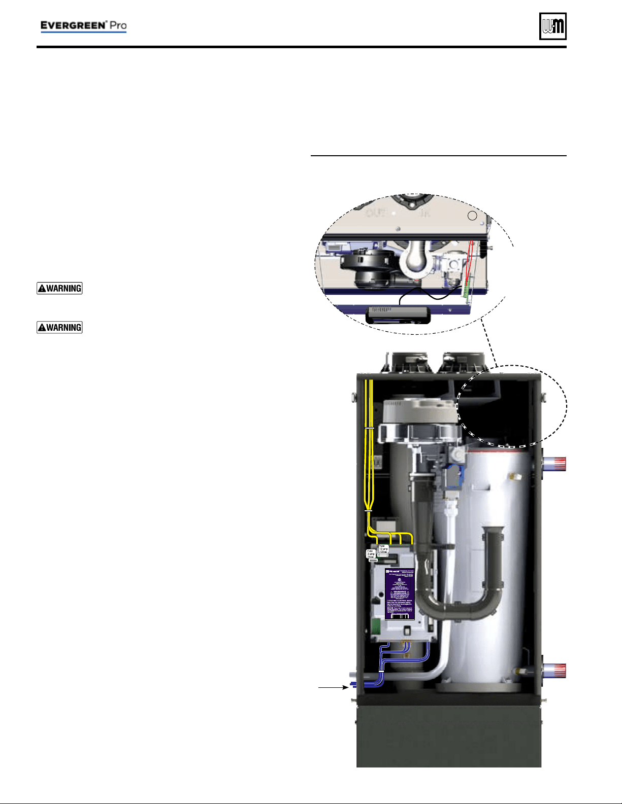
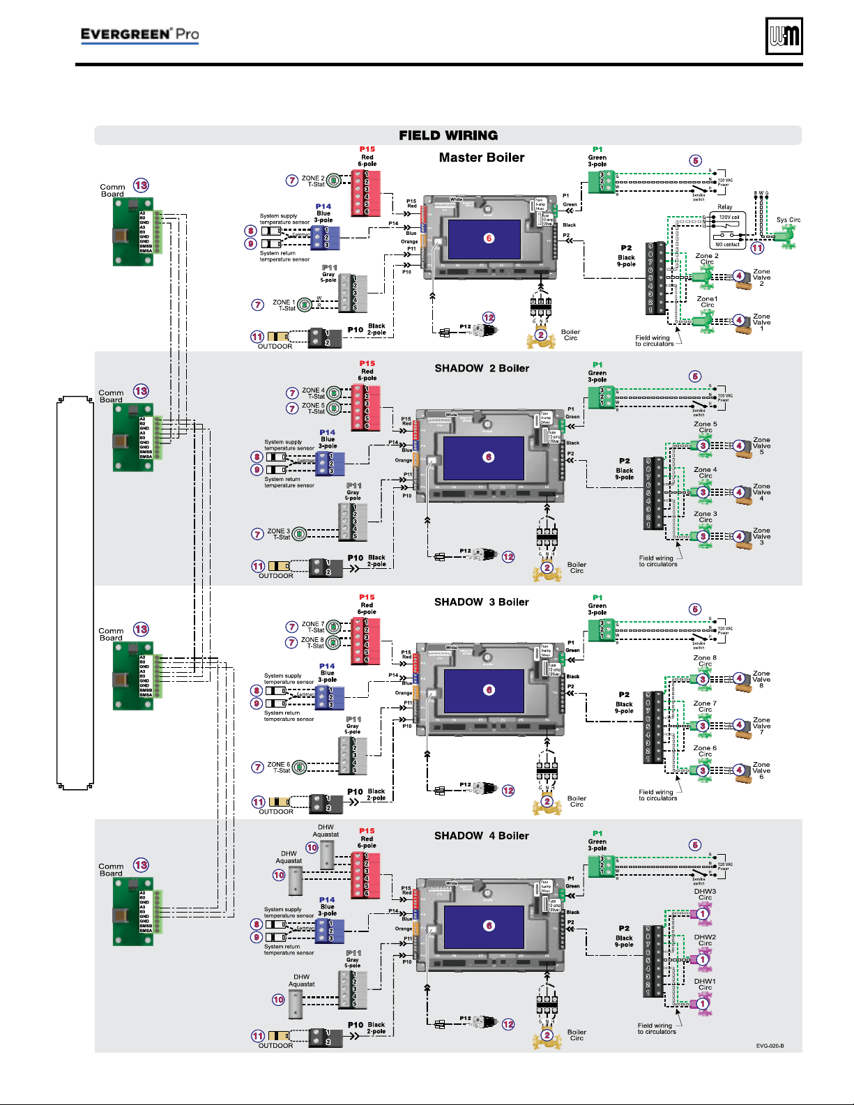
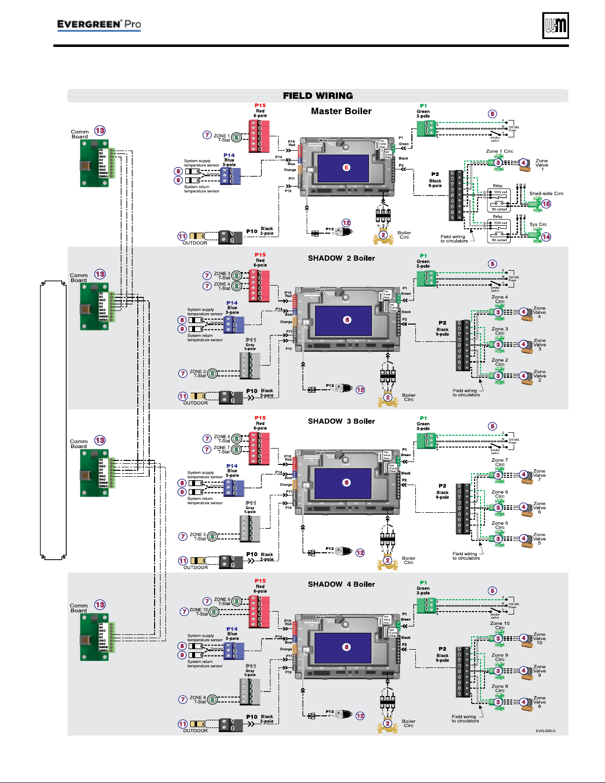
Field wiring (see wiring diagram, Figure 15, page 34 )
Figure 14 Field wiring overview (see Figure 15, page 34 and
Figure 16, page 35 for detailed schematic and ladder
wiring diagrams)
Line
Voltage
Multiple
boiler
communication
wiring
Low
Voltage
Part number 550-100-214/1220
– 26 –
CONDENSING GAS BOILER — 110/155 Advanced Manual
Evergreen
®
boiler wiring
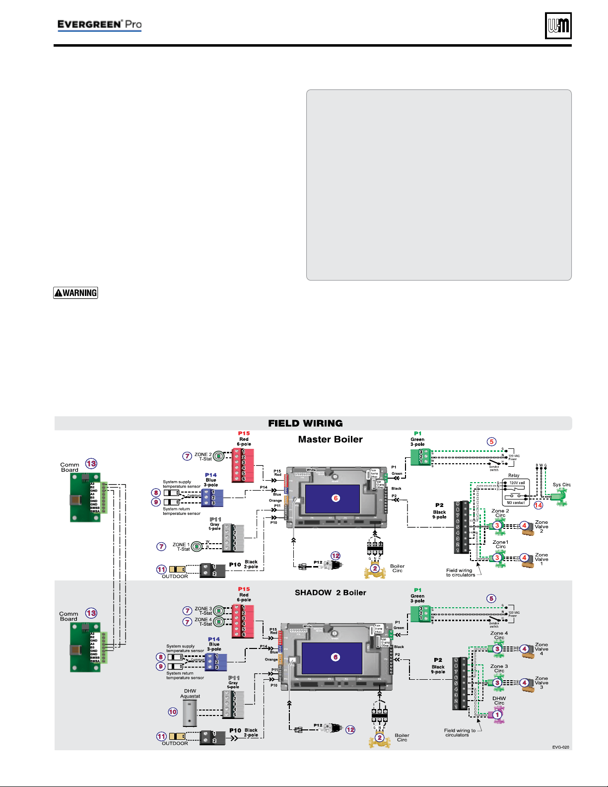
Connecting terminals
All fi eld wiring is made through the eight (8) colored connectors
(shipped loose with boiler) directly to the control module. Line volt-
age, 120 VAC, terminals are on the top of the control module. Low
voltage, 24 VAC, terminals are on the bottom of the control module.
Wire entrances
Wire entrance knockouts are provided on the top left, the bottom
left side and the top right side of the boiler cabinet:
1. Line voltage— fi ve (5) knockouts on the top left of the cabinet
(Line In, Output 1, 2, 3, Boiler Circ.).
2. Low voltage— two (2) knockouts on the bottom left side of
the cabinet.
3. Multiple boiler communication wiring—a single knockout on
the top right side of the cabinet.
Installer MUST use a strain relief through jacket
knockouts. Failure to do so can cause severe personal
injury, death or substantial property damage.
Installer MUST SEAL all electrical entrances using a
sealed strain relief or a strain relief sealed with duct
seal putty or silicone. Sealing the entrances prevents
the boiler from drawing air from inside the boiler
room. This is particularly important if the boiler is
located in the same room as other gas appliances.
Failure to seal entrances could result in sever per-
sonal injury, death or substantial property damage.
Wire routing in the cabinet
Line voltage:
(120VAC in, circulator outputs)
1. Install four (4) of the wire tie bases to the holes on the left side
interior of the cabinet.
2. Line voltage should be wired from the top left electrical en-
trances following the left side of the cabinet.
3. Wires should be bundled together and secure with the
provided wire ties to the wire tie bases located on the left
side wire chase. Two (2) sets of bases are provided, one (1)
for line in and one (1) for the circulator outputs. Route
wires in front of the transformer then into terminal blocks.
4. Strip end of wire no more than 1/8” to avoid exposing unin-
sulated wire.
5. It is recommended to install an On/Off service switch in a
junction box mounted near the boiler. Installation must meet
all National and local electrical codes.
Low voltage:
1. Mount low voltage wire grommet to desired low voltage
knockout.
2. Thermostat, aquastat, limit devices, system sensors, 0-10VDC
input and outdoor temperature sensor wire pairs should be
routed through the grommet.
3. Wires should be connected directly into the corresponding
terminal block.
4. Low water cutoff (optional) should be routed following the
instructions in step 3. Provide strain relief and a seal at cabinet
ent ry.
5. Bundle all wires together with provided wire ties.
6. After wires are attached to the control terminal blocks, make
sure wires are properly sealed in the cabinet electrical entrances.
Multiple boiler communication wiring
1. Wires should be shielded thermostat wires, or equivalent.
2. Route wires through top right knockout to communication
board on display bracket.
3. Provide strain relief and seal at cabinet entry.
Wiring to
Comm board
inside cabinet
boiler
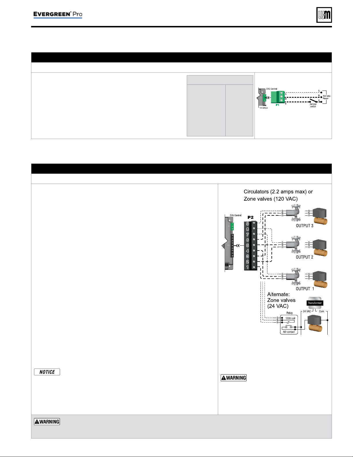
Part number 550-100-214/1220
– 27 –
CONDENSING GAS BOILER — 110/155 Advanced Manual
Field wiring (see wiring diagram, Figure 15, page 34 )
A. 120 VAC Power Supply – REQUIRE D
Terminal Block P1
1. Provide and install a properly-sized, fused disconnect or service
switch as required by applicable codes. (15-amp for most cases.)
a. Use table at right to determine total load.
2. Connect properly sized
120 VAC power wiring to Evergreen
®
boiler line voltage terminal strip P1 as shown at right.
3. If possible, provide a surge suppressor in the supply power
line. This will reduce the possibilities of control damage due
to line surges.
4. Must wire ground to this terminal to provide boiler grounding.
Determine total load
Boiler & boiler pump
(combined load)
Output 1 . . . . . . .
(2.0 amps max)
Output 2 . . . . . . .
(2.0 amps max)
Output 3 . . . . . . .
(2.0 amps max)
TOTAL . . . . . . .
5.6 amps
____ amps
____ amps
____ amps
____ amps
See Figure 15, page 34 for
details
B. 120 VAC Outputs 1, 2 & 3 – On each boiler – As needed for systems
Terminal Strip P2 (EVG control module)
1. Output 1: P2 Terminals 1 (H), 4 (N), 7 (G).
2. Output 2: P2 Terminals 2 (H), 5 (N), 8 (G).
3. Output 3: P2 Terminals 3 (H), 6 (N), 9 (G).
4. Maximum load: 2.2 amps (use relay if circulator load is higher). See WARN-
ING below.
5. Each boiler has three outputs (Output 1, Output 2, and Output 3) that provide
120 VAC to the following listed below.
• A zone
circulator.
• A system circulator.
• A DHW circulator (used to circulate through an indirect tank).
• An auxil
iary item that must be energized during an input call, such as
an air damper.
6. When using inputs/outputs for heat/DHW demands, each input (Input 1,
Input 2, and Input 3) controls its respective 120 VAC output (Output 1,
Output 2, and Output 3). Outputs are energized only when BOTH condi-
tions below are met:
a. The corresponding input indicates a call for heat/DHW (i.e., contact
closure).
b. The PRIORITY assigned to the Input/Output pair is ACTIVE (i.e., the
zone may be calling but the pump won’t activate unless the boiler is cur-
rently running on that system/priority).
7. When using the inputs/outputs for the AUX PUMP/OUTPUT function, the
output is controlled by selectable conditions set up in the control.
a. Use the AUX PUMP/OUTPUT function for devices such as system pumps,
combustion air dampers, and other auxiliary equipment to activate when
the boiler is on/running.
b. See page 56 and page 57 for more information on the setup and selection
of operating conditions.
For Priority DHW Application:
The DHW aquastat(s) and pumps can be connected to any one of
the three input/output pairs.
The selected input should be assigned to LOCAL or P1 if single,
PRIORITY 1 if direct piped to the boiler, or NETWORK PRIOR-
ITY 1 if located in the system. Set the assignment during the WIZ-
ARD setup or manually in the ASSIGN INPUTS menu.
See Figure 15, page 34 for details
Output circuits are 120 VAC. If an
output is to operate a low voltage
circuit or must be an isolated con-
tact, use an isolation relay. See
example above for 24 VAC zone
valves.
CIRCULATOR POWER — The maximum allow-
able current for each circulator is 2.2 amps
at 120 VAC
.
For circulators with higher amp ratings, install a circulator relay
or starter. Connect only the 120 VAC coil to the Evergreen®
circulator terminals.
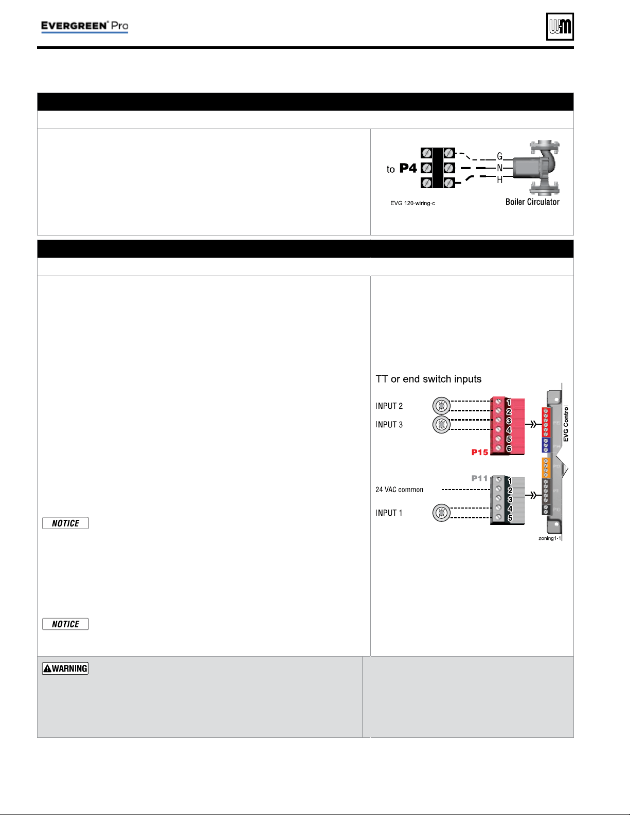
Part number 550-100-214/1220
– 28 –
CONDENSING GAS BOILER — 110/155 Advanced Manual
Field wiring (see wiring diagram, Figure 15, page 34 )(continued)
C. 120 VAC to Boiler Circulator – REQUIRED
Terminal Strip P4 on Comm Board
1. Provides 120 VAC to the boiler circulator at P4 Terminal to Control module.
2. Terminals are: 1 (H), 2 (N), 3 (G).
3. Maximum load: 2.0 amps (use relay if circulator load is higher). See WARN-
ING.
4. The boiler circulator (shipped loose with boiler) is used in the boiler loop of
the primary / secondary piping. Primary / secondary piping is required to
be used with the Evergreen® boiler to ensure proper fl ow through the heat
exchanger.
See Figure 15, page 34 for details
D. 24 VAC Inputs 1, 2 and 3 (tstats, end switches, etc.) – As needed for systems
Terminal Strip P11 (input 1) & Terminal Strip P15 (inputs 2 & 3) (EVG control module)
1. Input 1 – Terminal Strip P11 – 4 & 5 (EVG control module)
2. Input 2 – Terminal Strip P15 – 1 & 2 (EVG control module)
3. Input 3 – Terminal Strip P15 – 3 & 4 (EVG control module)
4. These three inputs on each boiler can indicate a call for heat to the control
by means of a dry contact closure (thermostat, aqua
stat, or switch). (See
right and Figure 15, page 34 ).
5. Each control provides input/output pairs for up to three zones or three systems
(priorities). For multiple boiler applications, this is true for each boiler (for
eight boilers, total is 3 x 8 or 24).
6. For DHW applications, the aquastat can be connected to one of the three
input/output pairs. Wire the DHW circulator to the corresponding output.
a. For minimum setup steps, take advantage of the factory default settings.
Use LOCAL PRIORITY 1 for the DHW circuit if piped directly to the
boiler, or NETWORK PRIORITY 1 if the DHW circuit is located in the
system as a zone.
b. For DHW circuits piped as a zone in a system with a system pump, setup
the control to run AUX PUMP/ OUTPUT during DHW operation. This
can be done during the WIZARD setup process. Note that the input used
for AUX PUMP/OUTPUT cannot be used to accept a heat input.
DHW circuit in system — For high-demand DHW circuits, the con-
trol setting for MIN BOILERS must be set using the NETWORK 1
or NETWORK 2 priority menu after the WIZARD is completed
to ensure quick response to demand. See page 53 for a description
of the MIN BOILERS setting.
7. The default control setting uses each input (INPUT 1, INPUT 2, and IN-
PUT 3) to control its respective 120 VAC output (OUTPUT 1, OUTPUT 2,
and OUTPUT 3).
Use of 0–10VDC input for modulation disables INPUT 1 from
creating calls for heat. This function can only be set up on single
boilers. See page 32 for instructions.
See Figure 15, page 34 for details
Thermostats — DO NOT supply 24-volt power to the thermostat
circuits (Input1, Input2 and Input3 in
Figure 15, page 34
) or
attempt to supply 24 volts for any other application.
For thermostats that require a continuous 24-volt power
source, connect the common wire (“C”) to
P11
Pin 2
(see Fig-
ure 15, page 34 )
. Do NOT exceed total amp draw per thermostat.
Zone valves — If using 3-wire zone valves, use
relays to provide dry contacts to the Control ther-
mostat connections. The zone valve end switches
of 3-wire valves carry 24 VAC from the valve.
Thermostat anticipator setting — 0.1 amps.
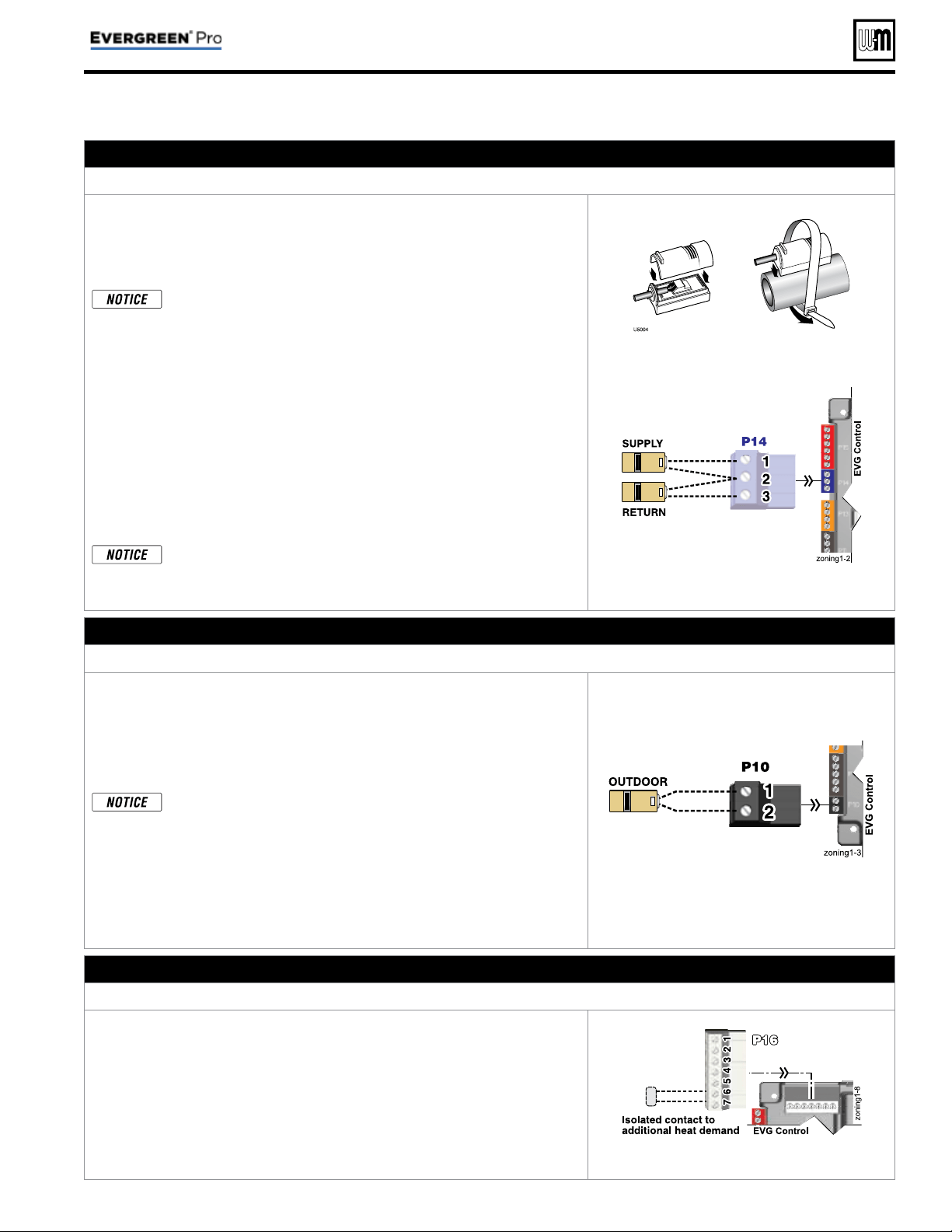
Part number 550-100-214/1220
– 29 –
CONDENSING GAS BOILER — 110/155 Advanced Manual
Field wiring (see wiring diagram, Figure 15, page 34 )(continued)
E. System supply and return temperature sensors – REQUIRED
Terminal Block P14 (EVG control module)
1. Two strap-on temperature sensors are shipped with each boiler. Attach one
to the system supply piping and the other to the system return piping. For
piping larger than 5 inch diameter or nonmetallic piping, using immersion
sensors will provide faster response. See Evergreen® boiler manual replace-
ment parts section for available immersion sensors.
Preferably, connect outdoor, system supply and system return sen-
sors to more than one boiler to provide redundancy. If one of the
sensors fails, the master boiler Evergreen® control automatically
look for an available sensor.
2. Locate the supply sensor at least six pipe diameters, but no further than 3
feet, downstream from the boiler connection to the main to ensure adequate
mixing.
3. Supply sensor – wire between P14 #1 and #2 (common).
4. Return sensor – wire between P14 #3 and #2 (common).
5. Thermostat wire can be used to connect these sensors.
6. The Control compares the system return temperature with the system supply
temperature. Should the return temperature ever exceed the supply tempera-
ture, the Control knows there is likely a sensor failure and will report this
problem on the display.
All heating systems shown in this manual require the System Sup-
ply and Return sensors to be installed for proper control function.
System will not properly provide heat if sensors are not installed
according to these instructions.
Strap to supply & return piping
See Figure 15, page 34 for details
F. Outdoor temperature sensor – REQUIRED unless exempted
Terminal Block P10 (EVG control module)
1. The control provides programmable options if using an outdoor tempera-
ture sensor. This sensor is supplied with the boiler.
2. The outdoor sensor must be installed unless specifi cally ex-
empted in the Energy Act statement on page 2 .
3. Mount the outdoor sensor on an exterior wall, shielded from direct sunlight
or fl ow of heat or cooling from other sources.
Preferably, connect outdoor, system supply and system return sen-
sors to more than one boiler to provide redundancy. If one of the
sensors fails, the master boiler Evergreen® control automatically
look for an available sensor.
4. The wire outlet on the sensor must be oriented DOWN to prevent water
entry.
5. Connect the sensor leads to the terminal shown at right and in the wiring
diagrams (see Figure 15, page 34 ). Thermostat wire can be used to connect
the sensor.
See Figure 15, page 34 for details
G. Additional heat demand contacts – OPTIONAL
Terminal Block P16 #6 & #7 (EVG control module)
1. Each boiler’s control module can be set to activate another heat source using its
additional heat demand dry contacts through terminal block P16 pins 6 & 7.
2. Connect these terminals to call for heat from the other heat source.
3. Set the control to activate the heat demand contacts as needed.
4. The setup is done in the priority menu for the priority that will call for the
additional heat operation. See page 55 for details.
5. Contact electrical ratings: 24 VAC or less; 0.5 amp or less.
6. See “Add’l Heat Demand” on page 53 regarding which boilers may use this
function, depending on the priority being used.
See Figure 15, page 34 for details
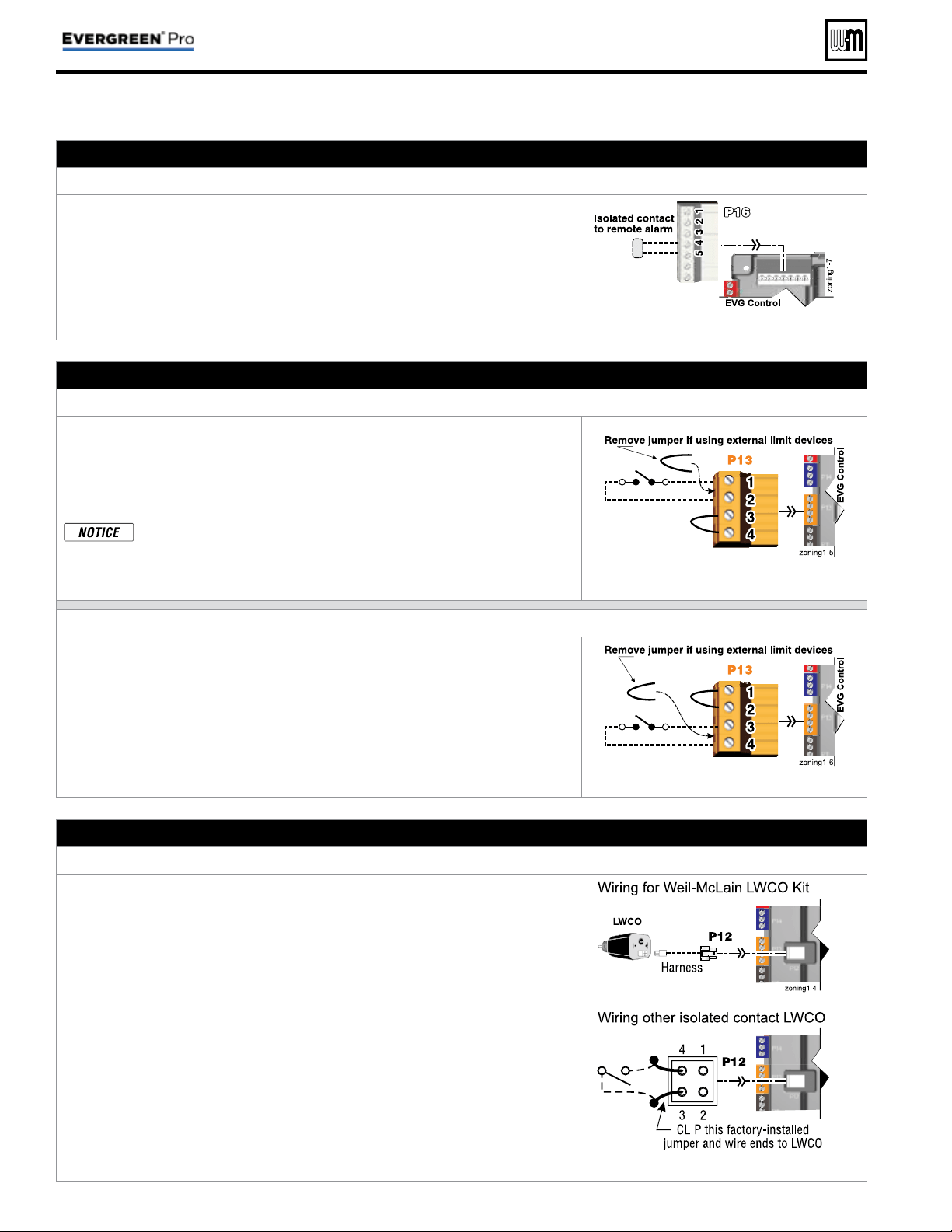
Part number 550-100-214/1220
– 30 –
CONDENSING GAS BOILER — 110/155 Advanced Manual
H. Alarm contacts – OPTIONAL
Terminal Block P16 #4 & #5 (EVG control module)
1. The control’s alarm dry contact (P16, terminals 4 and 5) closes when the
boiler enters manual lockout only.
2. Connect these terminals for remote alarm notifi cation.
3. Contact electrical ratings: 24 VAC or less; 0.5 amp or less.
See Figure 15, page 34 for details
I. External limits – OPTIONAL
To cause MANUAL reset: Terminal Block P13 #1 & #2 (EVG control module)
EVG control will require manual reset after circuit is interrupted
1. Remove factory-installed jumper and connect isolated contacts of external
limits across P13 pins 1 and 2 to cause the control to enter manual reset lock-
out if the limit circuit opens. The limit must close and the control must be
manually reset using the procedure given in this manual. See drawing at right
and wiring diagram ( Figure 15, page 34 ).
The control will lockout when a limit in its manual reset circuit opens
(P13 pins 1 & 2). The control activates its alarm terminals and shuts
the boiler off. An operator (user or technician) must manually reset
the control to resume heating. Cycling power on and off will NOT
reset the control.
See Figure 15, page 34 for details
To cause AUTOMATIC reset: Terminal Block P13 #3 & #4 (EVG control module)
EVG control will reset automatically after circuit is interrupted
1. Remove factory-installed jumper and connect isolated contacts of external
limits across P13 pins 3 and 4 to cause the control to shut down the burner
on limit opening, then automatically restart 150 seconds after the limit closes.
2. See drawing at right and wiring diagram ( Figure 15, page 34 ).
See Figure 15, page 34 for details
J. Low water cutoff – WHEN REQUIRED
Terminal Block P12 (EVG control module)
1. Install a low water cut-off when required.
2. Wiring Weil-McLain LWCO Kit
a. When possible, use the Weil-McLain Low water cut-off kit listed in the
Boiler manual replacement parts section. It includes a probe-type low
water cut-off and provides a simple harness connection for the wiring.
b. Connect as shown at top right and in the control wiring diagram ( Fig-
ure 15, page 34 ).
c. The Weil-McLain Low water cut-off kit is included with the boiler.
3. Wiring another LWCO — must have isolated contact
a. Other low water cut-offs can be used with the EVG only if the device uses
an isolated contact for the LWCO function.
b. Connect as shown at bottom right.
See Figure 15, page 34 for details
Field wiring (see wiring diagram, Figure 15, page 34 )(continued)
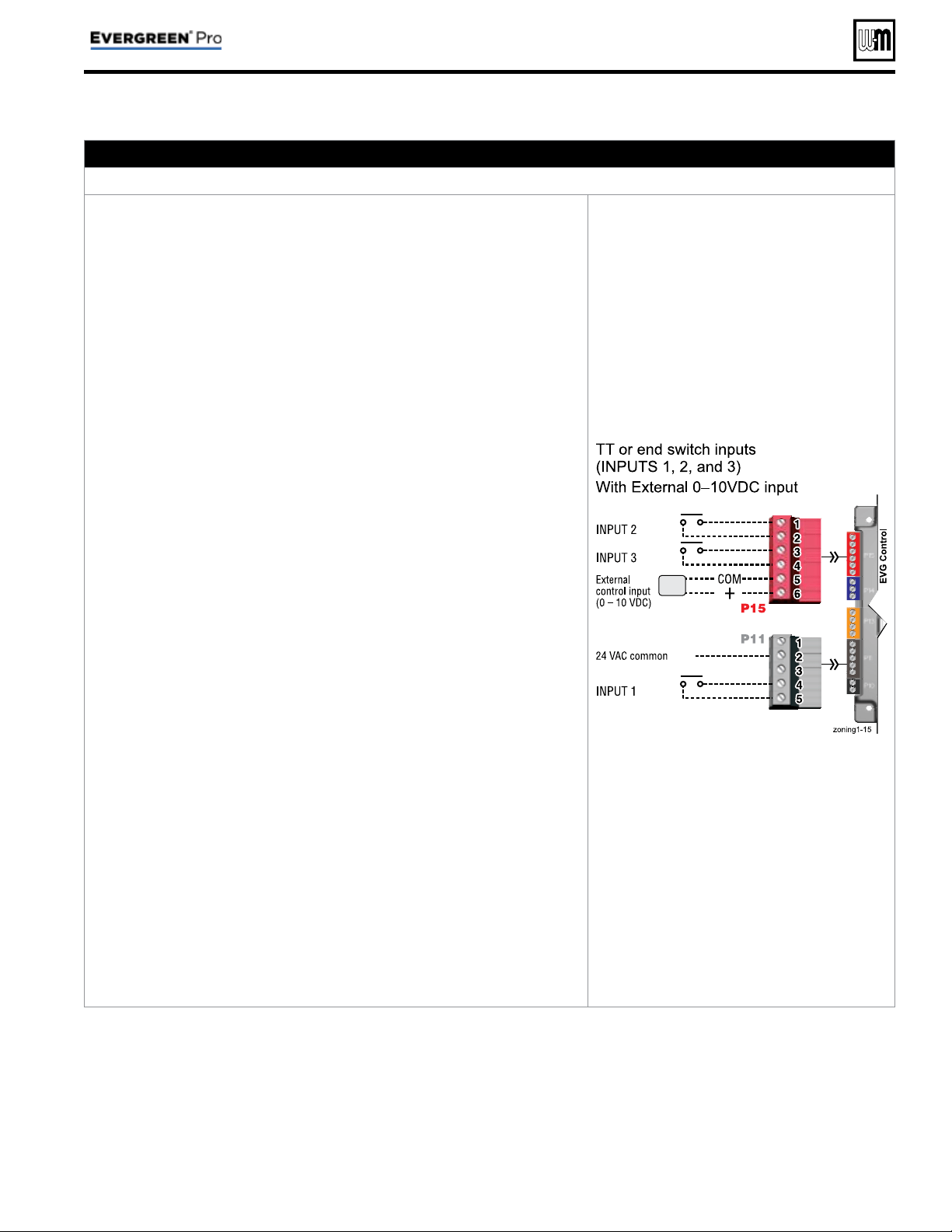
Part number 550-100-214/1220
– 31 –
CONDENSING GAS BOILER — 110/155 Advanced Manual
K. 0–10 VDC Remote TARGET input – OPTIONAL
Terminal Block P15 #5 & #6 (EVG control module)
1. See illustration at right and Figure 15, page 34 (wiring diagram) for details.
2. Remote target using 0–10VDC input requires a 0–10VDC input signal at
P15-5/6 as shown at right.
a. The input positive connection must be at P15 terminal 6 and the common
connection at terminal 5.
b. Using PRIORITY 1, 2, or 3 for single boiler, or LOCAL PRIORITY 1 or
LOCAL PRIORITY 2 for a network boiler.
The 0–10VDC input must be
to that boiler
.
c. Using NETWORK PRIORITY 1 or NETWORK PRIORITY 2 for a net-
work boiler. The 0–10VDC input must be made to the MASTER boiler
of the network
.
3. The illustration at right also shows how to connect TT or end switch contacts
at INPUT 1, INPUT 2 and INPUT 3 of any boiler.
a. If the target controller has a heat demand contact, connect it to one of
the INPUTs and set up in the WIZARD or manually.
b. A dry contact heat demand must be applied to one of the inputs in order
to initiate a call for heat.
4. The 0–10VDC signal is used to adjust the supply target temperature, using
the TARGET ADJUST setting. Set TARGET ADJUST during the WIZARD
or manually in the setup menu for the priority chosen.
5.
Suggested 0–10VDC remote target setup for single boiler or a local
priority
:
a. Use PRIORITY 1 (or LOCAL PRIORITY 1) for the DHW heating circuit
when used. This priority’s default values are set for DHW, direct-con-
nected to the boiler. Verify that settings are suitable for the application,
changing if needed.
b. Use PRIORITY 2 (or LOCAL PRIORITY 2) for the heating circuit that
uses the 0–10VDC input.
• For single boilers, the factory default settings for either of these pri-
orities make them a good choice for space heating applications. Set
priority values to the following:
• Set TARGET ADJUST value to 0–10V.
• Set VOLTS FOR MAX at the voltage that will call for the highest target
temperature. Set SUPPLY MAX at this temperature.
• Set VOLTS FOR MIN at the voltage that will call for the lowest target
temperature. Set SUPPLY MIN at this temperature.
• For voltages between VOLTS FOR MAX and VOLTS FOR MIN, the
target temperature will range proportionately between SUPPLY MAX
and SUPPLY MIN.
• NOTE: The 0–10VDC signal replaces the ODT sensor as the target
temperature modifi er (TARGET ADJUST setting). The EVG control
does not control target.
6.
Suggested 0–10VDC remote target setup for a network priority:
a. Setup the control as above, but select NETWORK PRIORITY 2 for the
heating circuit that uses the 0–10VDC input..
b. If a local (direct-connected) DHW circuit is used, select LOCAL PRIOR-
ITY 1 for DHW. If a DHW circuit in the system is used, select NETWORK
PRIORITY 1 for DHW.
See Figure 15, page 34 for details
Field wiring (see wiring diagram, Figure 15, page 34 )(continued)
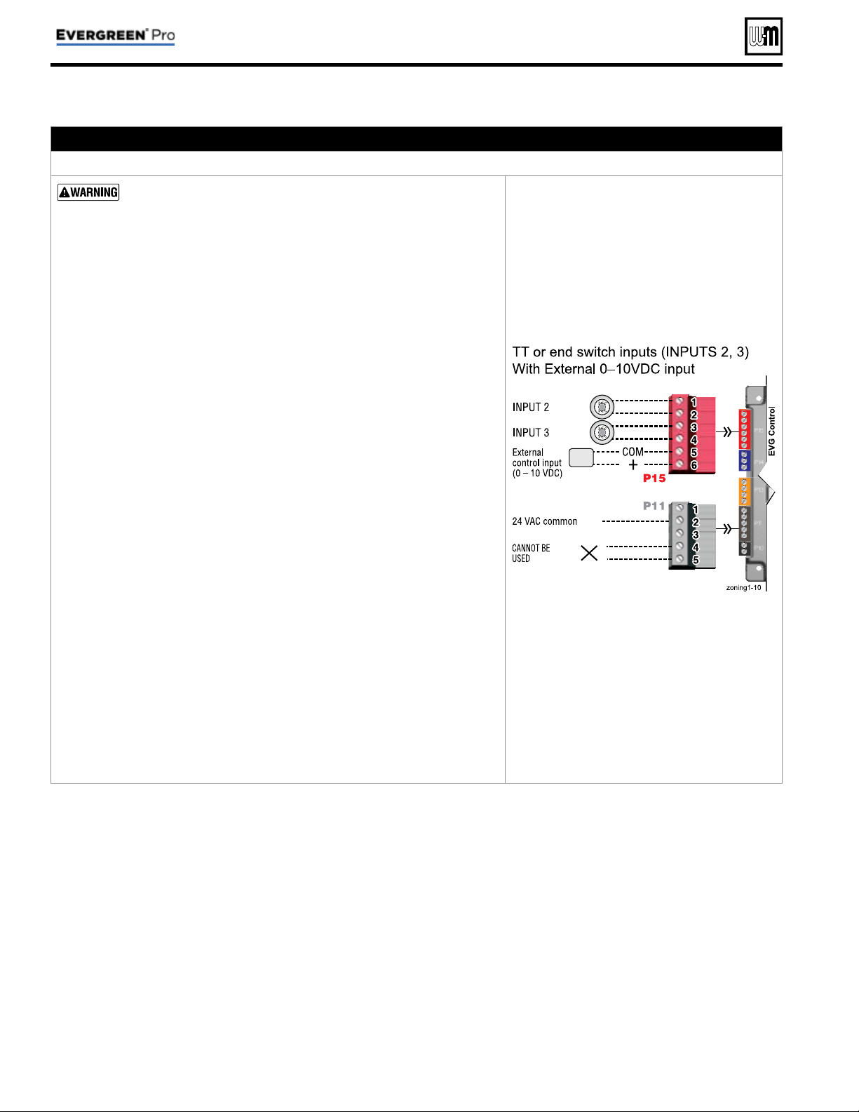
Part number 550-100-214/1220
– 32 –
CONDENSING GAS BOILER — 110/155 Advanced Manual
Field wiring (see wiring diagram, Figure 15, page 34 )(continued)
L. 0–10 VDC Remote MODULATION input – OPTIONAL
Terminal Block P15 #5 & #6 (EVG control module)
Using an external multiple boiler controller — Remote modula-
tion using an external controller only works with each boiler set up
as a SINGLE boiler in the EVG Control setup.
1. See illustration at right and Figure 15, page 34 for details.
2. This illustration also shows how to connect TT or end switch contacts at
INPUT 2 and INPUT 3 for other uses.
3. This function can only be used with a single boiler, NOT for a boiler in a
network.
4. Note that using 0–10VDC input replaces INPUT 1 for generating a heat
demand. Do not wire any input to INPUT 1 as shown at right.
5. Remote modulation requires a 0–10VDC input signal at P15-4/5 as shown
at right.
a. The 0–10VDC input positive connection must be at terminal 6 and com-
mon connection at terminal 5.
6. Control setup:
a. Many options are available for confi guring the control. The following is
a suggested setup that uses factory default settings as much as possible.
b. If DHW is required, use PRIORITY 1 to minimize setup steps.
• Connect the DHW aquastat to INPUT 2 or INPUT 3 and assign the
input used to PRIORITY 1.
• Verify that control settings are suitable for the application, changing
if necessary.
c. Use PRIORITY 2 for the system to be remote modulated.
• The factory default settings for this priority are best suited for space
heating.
• Assign INPUT 1 to the priority chosen. Accept all defaults for INPUT 1
— no changes should be necessary during the WIZARD.
• After the WIZARD has been completed, go to the ASSIGN INPUTS
menu for INPUT 1. Change SOURCE to 0–10V (default setting is
TT1). See page 56 for ASSIGN INPUTS menu information.
7. Operation:
a. The boiler comes on at 0.9VDC and turns off at 0.8VDC. 2 VDC = 20%
input. 10 VDC = 100% input. These voltage settings are not adjustable.
b. OUTPUT 1 (120 VAC) is activated and deactivated as the heat demand
is turned on and off. This output is a good choice to operate the system
pump.
8. NOTE: The EVG control can be confi gured to use either 0–10VDC for target
operation (see previous section) or modulation,
but not both.
See Figure 15, page 34 for details
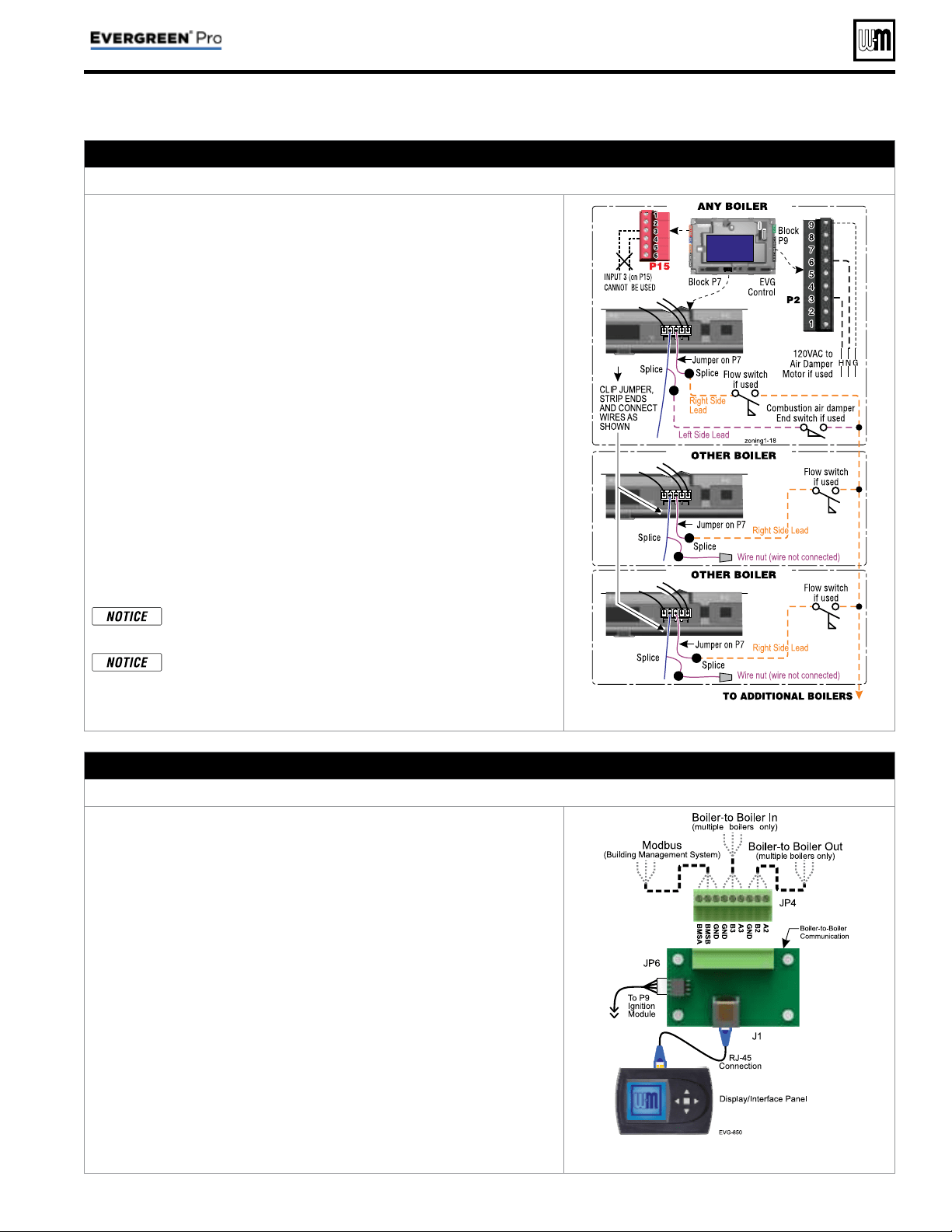
Part number 550-100-214/1220
– 33 –
CONDENSING GAS BOILER — 110/155 Advanced Manual
M. Proof of closure (fl ow switch and/or CAD)
– OPTIONAL
Jumper on Terminal Strip P7 (EVG control)
1. A fl ow switch or combustion air damper (CAD) interlock can be con-
fi gured by clipping the jumper on terminal strip P7. Strip the jumper
ends and wire components as shown at right and in the wiring diagram
( Figure 15, page 34 ).
2. No control settings are required when using a fl ow switch.
a. Each boiler is assumed to have its own fl ow switch, wired as shown
at right.
3. To confi gure the EVG control for a CAD interlock:
a. Assign any INPUT (recommend
INPUT 3) as a AUX PUMP/ OUT-
PUT
function. For multiple boiler applications, use any input on
any boiler in the network
. The example at right demonstrates using
INPUT/OUTPUT 3 on the MASTER boiler.
b. For the AUX PUMP/ OUTPUT operating mode, select ANY BURNER
DEMAND. This ensures the damper will be activated any time any
boiler is called on to fi re.
c. Wire the corresponding
OUTPUT (following recommendation,
OUTPUT 3) to provide 120 VAC to the damper motor when activated.
Use an isolation relay if damper motor requires another voltage or
more than 2.0 amps on 120 VAC.
d. For a multiple boiler system, when any boiler is called on to fi re,
whether for local or network demand, the combustion air damper will
be powered (120 VAC) from the assigned boiler
OUTPUT as shown
at right (using OUTPUT 3 on the master boiler).
The devices used must provide electrically isolated contacts,
because the P7 jumper circuit carries 5 VDC.
Ensure that the wires are connected only as shown. The right
side of each jumper must connect only to the right side of
other jumpers
. Failure to comply will cause incorrect opera-
tion of the proof of closure circuits.
See Figure 15, page 34 for details
N. Multiple Boiler and BMS Connections
Terminal Strip JP4 on Comm Board (display bracket right side)
1. The boiler control is capable of multiple boiler communication and
control of up to eight Evergreen
®
boilers in one installation.
2. The boiler control is also capable of BMS (Building Management System)
communication.
3. See wiring at right and in the wiring diagram ( Figure 15, page 34 ).
4. Use shielded 3-wire cable. Do not exceed 1,000 feet wire length.
5. Boiler to Boiler wiring connections
a. Connect 3-wire cable between Boiler-to-Boiler OUT (JP4-GND, B2,
A2) on one boiler to Boiler-to-Boiler IN (JP4-GND, B3, A3) on the
next boiler.
b. Continue this wiring until all boilers are interconnected.
6. MODBUS to BMS (Building Management System)
a. The control is equipped with MODBUS communication to com-
municate with a BMS.
b. Use terminal JP4 (JP4-BMSA, BMSB, GND) to wire to the BMS
control.
c. If the BMS uses BACnet protocol, install a BACnet converter between
the BMS and the Evergreen
®
MODBUS-to-BMS terminals (P5).
See Figure 15, page 34 for details
Field wiring (see wiring diagram, Figure 15, page 34 )(continued)
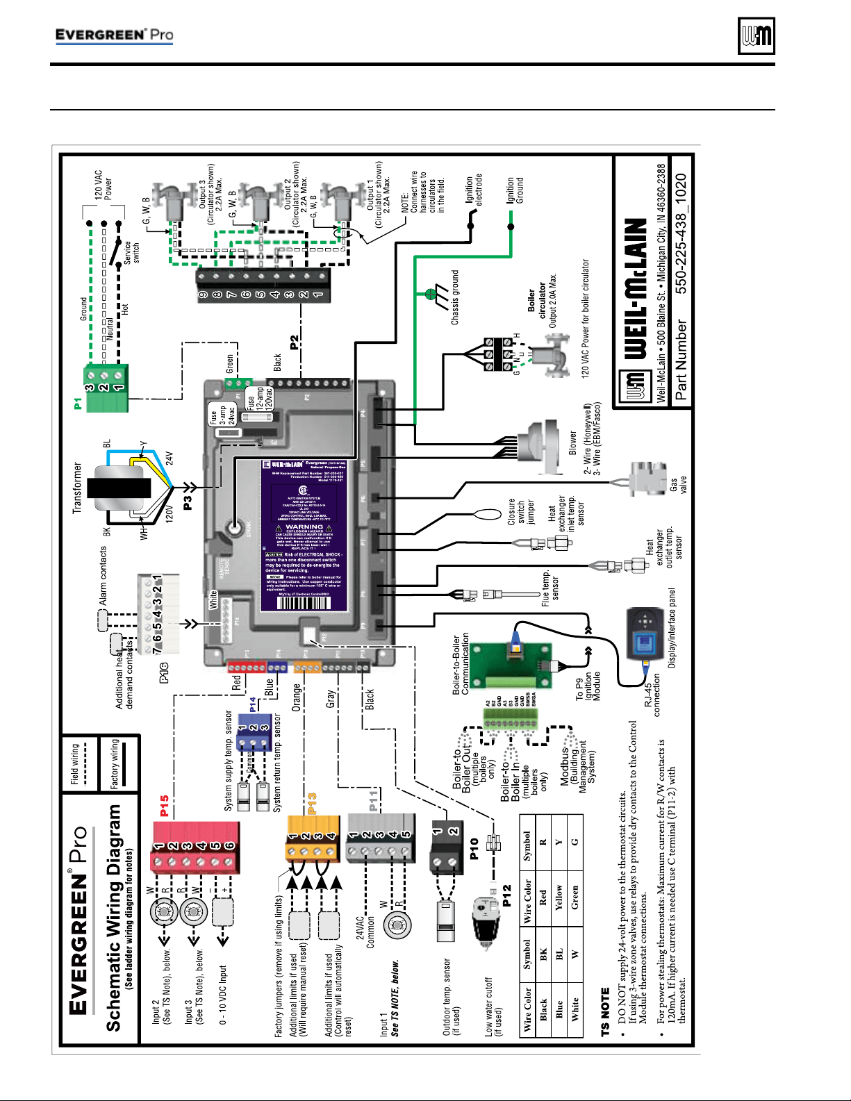
Wiring diagram — schematic
Figure 15 Evergreen
®
schematic wiring diagram (see Figure 16, page 35 for legend and notes)
Part number 550-100-214/1220
– 34 –
CONDENSING GAS BOILER — 110/155 Advanced Manual
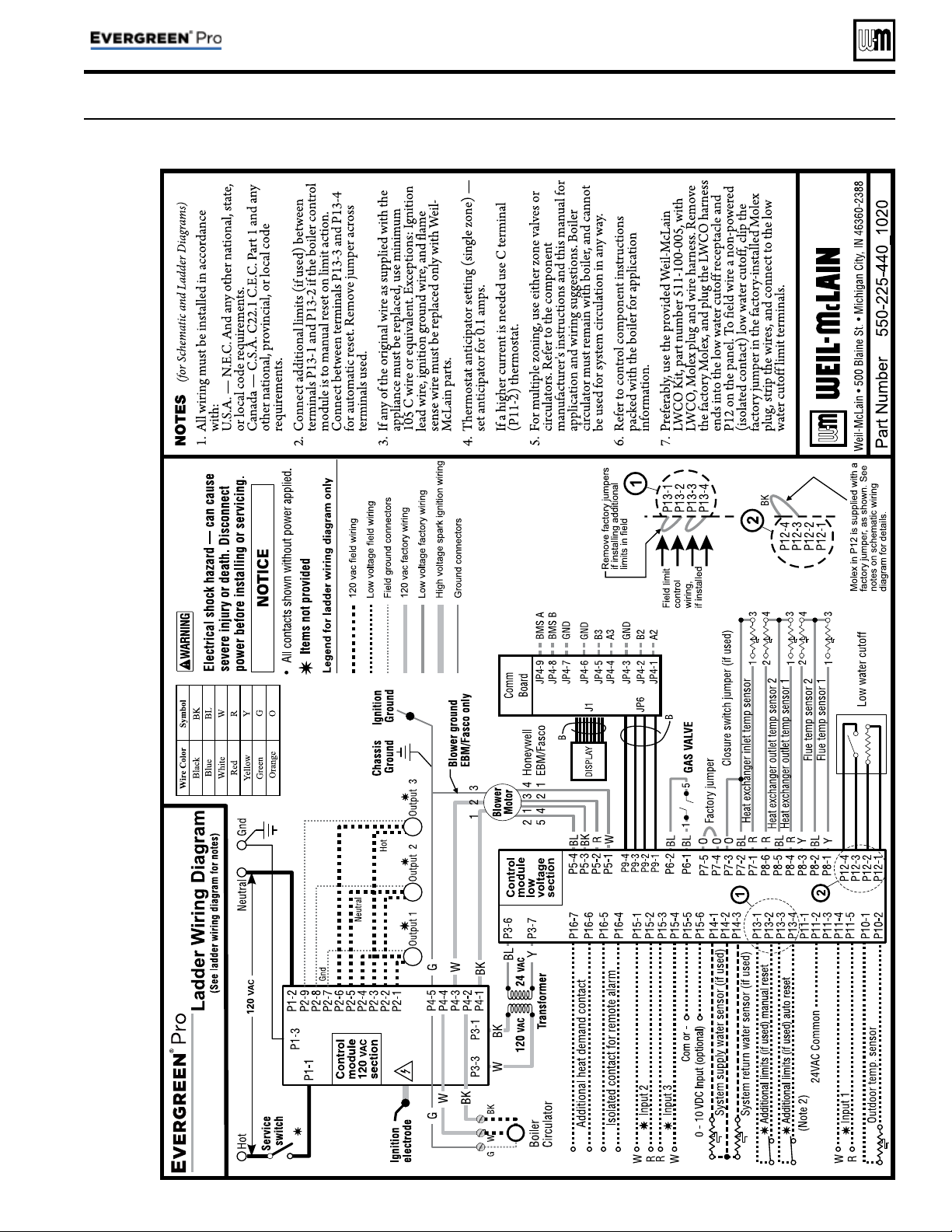
Wiring diagram — ladder
Figure 16 Evergreen
®
ladder wiring diagram (see Figure 15, page 34 for schematic wiring diagram)
Part number 550-100-214/1220
– 35 –
CONDENSING GAS BOILER — 110/155 Advanced Manual
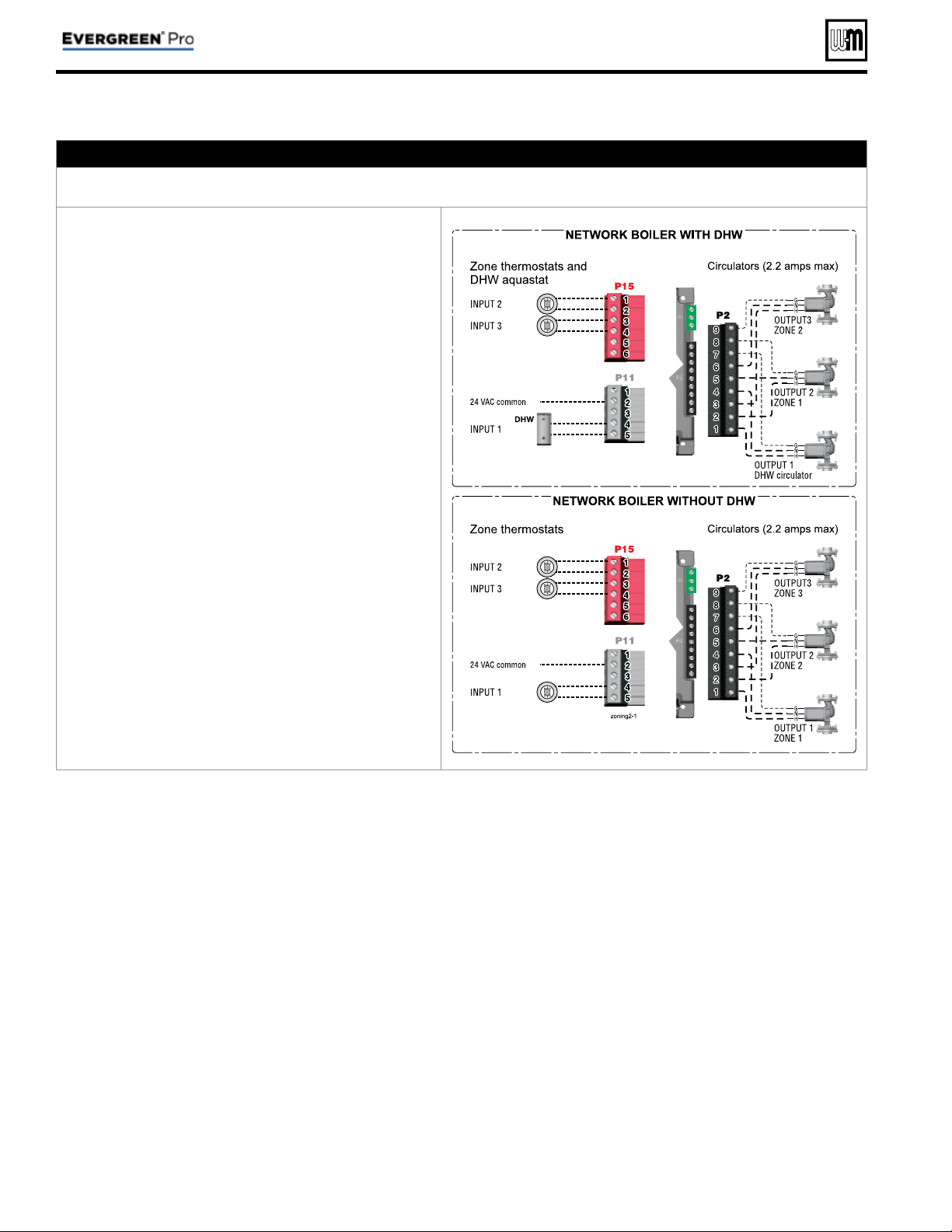
Zoning with the EVG Control
A. Zoning with CIRCULATOR S, suggested applications
Multiple space heating zones — Optional DHW direct-piped to one or more boilers
1. Review wiring information on page 27 (120 VAC out-
puts) and page 28 (24 VAC inputs).
2. The confi guration at right uses the three input/output
pairs of each boiler to receive thermostat (or DHW
aquastat) inputs on P11-4/5, P15-1/2, and P15-3/4;
and circulator outputs on P2 as shown.
3. Assign as many available input/output pairs in the
network as needed for zoning.
4. Individual boilers can be confi gured to operate direct-
piped DHW loads as shown at right. Individual boilers
can also be used for other direct-piped loads.
5. Setting the controls for network space heating zones:
a. Recommended — assign the space heating input/
outputs to NETWORK PRIORITY 2. The factory set-
tings default to space heating, reducing the changes
needed to set up the controls.
b. Choose the space heating system type that matches
the heating system during the WIZARD setup or
manually in the NETWORK PRIORITY 2 menu.
c. Use the factory default settings for the system type
chosen, or change if needed.
6. Setting the controls for individual boiler DHW loads:
a. Assign the input/output connected to the DHW
loop to LOCAL PRIORITY 1, which defaults to
settings for DHW.
b. Verify that settings are acceptable. Change if
needed.
7. Factory defaults should work for most other settings
not listed above.
Part number 550-100-214/1220
– 36 –
CONDENSING GAS BOILER — 110/155 Advanced Manual
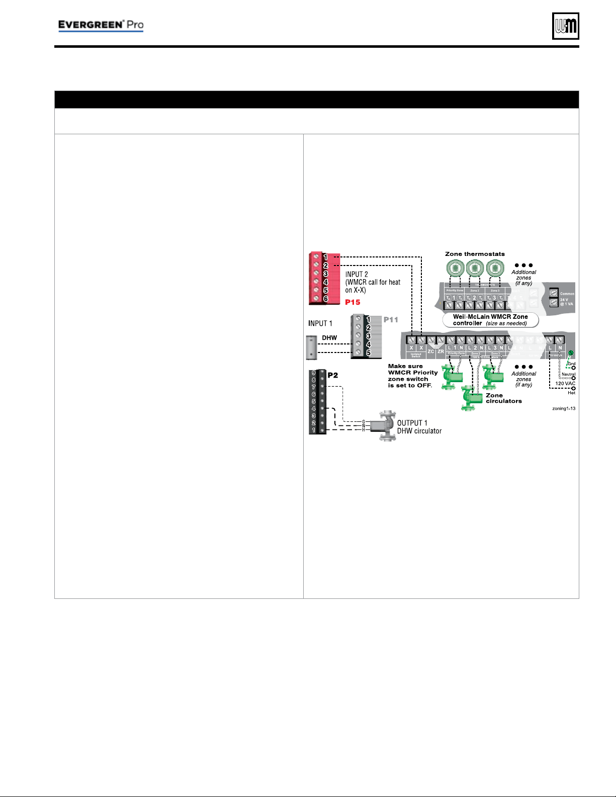
B. Zoning with CIRCULATOR S, suggested applications
WMCR circulator zone controller plus DHW controlled by boiler, Optional DHW
1. Review wiring information on page 27 (120 VAC out-
puts) and page 28 (24 VAC inputs).
2.
To shut down space heating during DHW operation
:
Provide and connect relay
R1
(120 VAC coil with NC
contact) to interrupt the zone controller’s ZC-ZR (120
VAC operating circuit).
a. This is required in all applications where the DHW
loop is piped in the system, not directly piped to
a boiler. Also, the boiler circulator must be set to
operate during DHW calls for system DHW ap-
plications.
b. For local DHW applications (DHW direct-piped to
a boiler), this relay is optional. Space heating pumps
will operate when called on by the zone controller,
but no heat will be delivered to the system — the
boiler circulator will not run during DHW heating.
3. This application example provides domestic priority
by using the EVG control(s).
4. The confi guration at right uses INPUT 2 on any boiler
for space heating with the call for heat coming from
the zone controller (X-X).
5. INPUT 1 is connected to a DHW aquastat.
6. This confi guration applies to either a local demand
(direct-piped to a single boiler) or a network demand
(piped to the main system).
7. Suggested for space heating: Assign INPUT 2 to either
LOCAL PRIORITY 2 (direct) or NETWORK PRIOR-
ITY 2 (system). To set up the priority, choose the space
heating system type that matches the heating system
during the WIZARD setup or manually in the prior-
ity menu.
8. Suggested for DHW: Assign INPUT 1 to either LOCAL
PRIORITY 1 (direct) or NETWORK PRIORITY 1
(system). Wire the DHW circulator to OUTPUT 1. Set
the control for boiler pump ON if DHW is network
piped. Set the control for boiler pump OFF if DHW is
direct-piped to a boiler (local).
9. Use the factory default settings for DHW and for the
heating system type chosen, or change if needed. Fac-
tory defaults should work for other settings not listed
above.
P15, P11, and P2 are terminal strips on the EVG control
Relay
R1, when used, is provided by installer
Zoning with the EVG Control (continued)
Part number 550-100-214/1220
– 37 –
CONDENSING GAS BOILER — 110/155 Advanced Manual
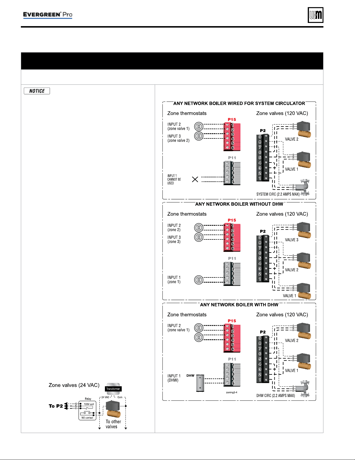
Zoning with the EVG Control (continued)
C. Zoning with ZONE VALVES, multiple boilers, suggested applications
(see EVG Boiler Manual for single boiler suggested applications)
Multiple space heating zones with direct-piped DHW on one or more boilers (optional)
This suggested application only applies
to systems with DHW piped directly to
individual boilers. For systems with DHW
connected to the system other control ar-
rangements may be required.
1. Review wiring information on page 27 (120 VAC
outputs) and page 28 (24 VAC inputs).
2. The confi gurations at right use the three input/out-
put pairs of each boiler (except INPUT/OUTPUT 1
on the boiler wired for system circulator) to receive
thermostat (or DHW aquastat) inputs on P11-4/5,
P15-1/2, and P15-3/4. The space heating system
circulator is connected to OUTPUT 1 (terminals 1,
4, and 7 on P2).
3. Assign as many available input/output pairs in the
network as needed for zoning.
4. Setting the controls for network space heating zones:
a. Recommended — assign the space heating input/
outputs to NETWORK PRIORITY 2. The factory
settings default to space heating, reducing the
changes needed to set up the controls.
b. Choose the space heating system type that
matches the heating system during the WIZARD
setup or manually in the NETWORK PRIOR-
ITY 2 menu.
c. Use the factory default settings for the system
type chosen, or change if needed.
5. On the boiler that is used for system circulator, as-
sign INPUT 1 to AUX PUMP/ OUTPUT. Then select
ANY INPUT BY ITS PRIORITY when prompted
for when to activate the output. This will cause the
system pump to run when any of the space heating
zones calls for heat.
6. Setting the controls for individual boiler DHW
loads:
a. Assign the INPUT that is wired to the DHW
aquastat to LOCAL PRIORITY 1, which defaults
to settings for DHW.
b. Verify that settings are acceptable. Change if
needed.
7. On the boiler that is used for system circulator,
Input 1 cannot be used for a wired connection (as
shown in the top right diagram.)
8. Factory defaults should work for other settings not
listed above.
9. Wire 24 VAC zone valves as shown below:
P15, P11, and P2 are terminal strips on the EVG control
(See wiring at left for 24 VAC zone valves).
Part number 550-100-214/1220
– 38 –
CONDENSING GAS BOILER — 110/155 Advanced Manual
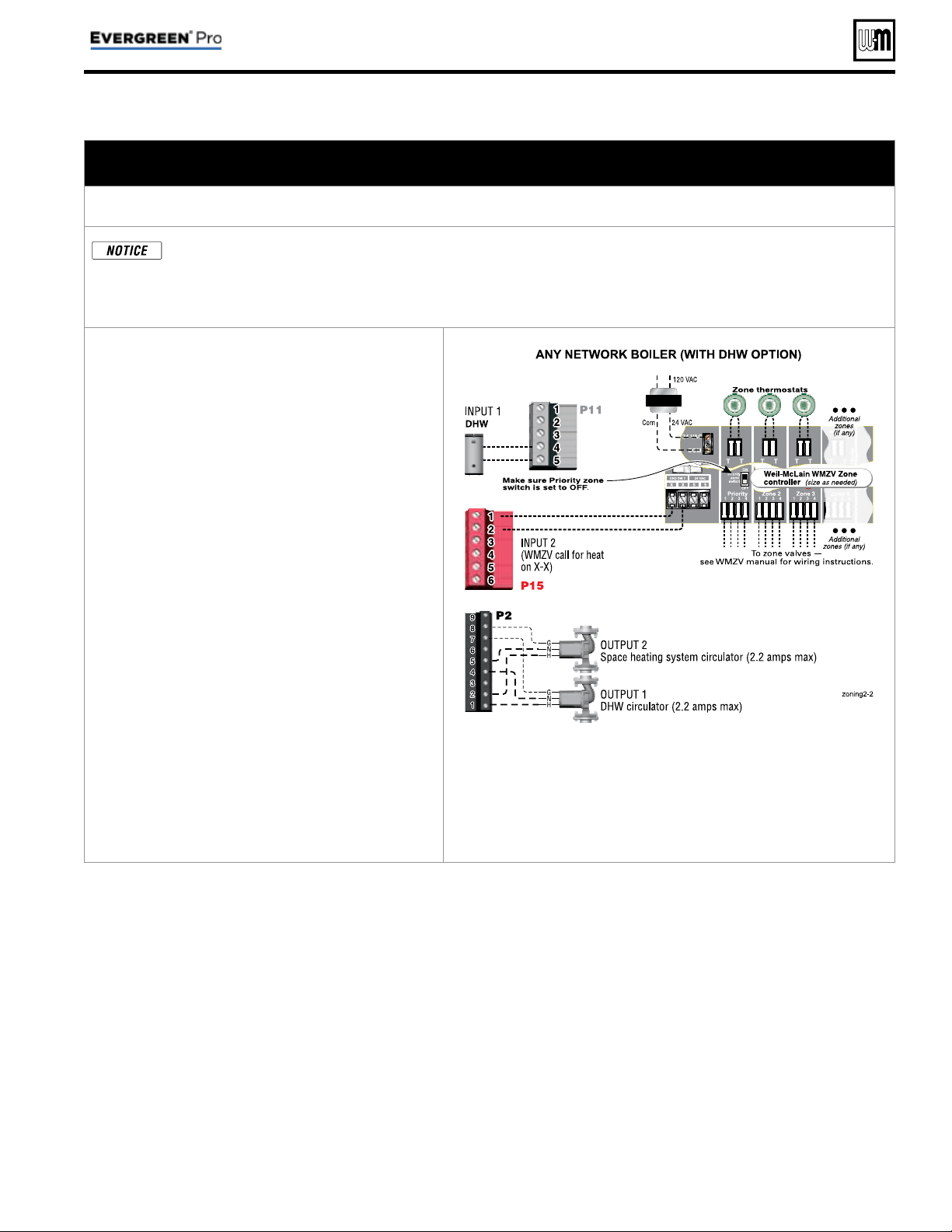
Zoning with the EVG Control (continued)
D. Zoning with ZONE VALVES, multiple boilers, suggested applications
(see EVG Boiler Manual for single boiler suggested applications)
WMZV zone valve zone controller plus DHW controlled by boiler, Optional DHW
This suggested application only applies to systems with DHW piped directly to individual boilers. For systems
with DHW connected to the system, other control arrangements may be required.
The wiring shown here will also work for a system as in Typical Application B on page 18 . This uses two systems
piped in parallel. If the space heating system pump is turned off, no heat is delivered to the space heating loop.
1. Review wiring information on page 27 (120 VAC
outputs) and page 28 (24 VAC inputs).
2. This application example provides domestic pri-
ority by using the EVG control(s). Space heating
pumps will operate when called on by the zone
controller, but no heat will be delivered to the
system — the boiler circulator will not run during
DHW heating.
3. The confi guration at right uses INPUT 2 on any
boiler for space heating with the call for heat com-
ing from the zone controller (X-X).
4. INPUT 1 is connected to a DHW aquastat.
5. This confi guration applies to either a local demand
(direct-piped to a single boiler) or a network de-
mand (piped to the main system).
6. Suggested for space heating: Assign INPUT 2 to
either LOCAL PRIORITY 2 (direct) or NETWORK
PRIORITY 2 (system). To set up the priority,
choose the space heating system type that matches
the heating system during the WIZARD setup or
manually in the priority menu.
7. Suggested for DHW: Assign INPUT 1 to LOCAL
PRIORITY 1. Wire the DHW circulator to OUT-
PUT 1. Set the control for boiler pump OFF during
DHW calls.
8. Use the factory default settings for DHW and
for the heating system type chosen, or change if
needed. Factory defaults should work for other
settings not listed above.
P15, P11, and P2 are terminal strips on the EVG control.
Part number 550-100-214/1220
– 39 –
CONDENSING GAS BOILER — 110/155 Advanced Manual
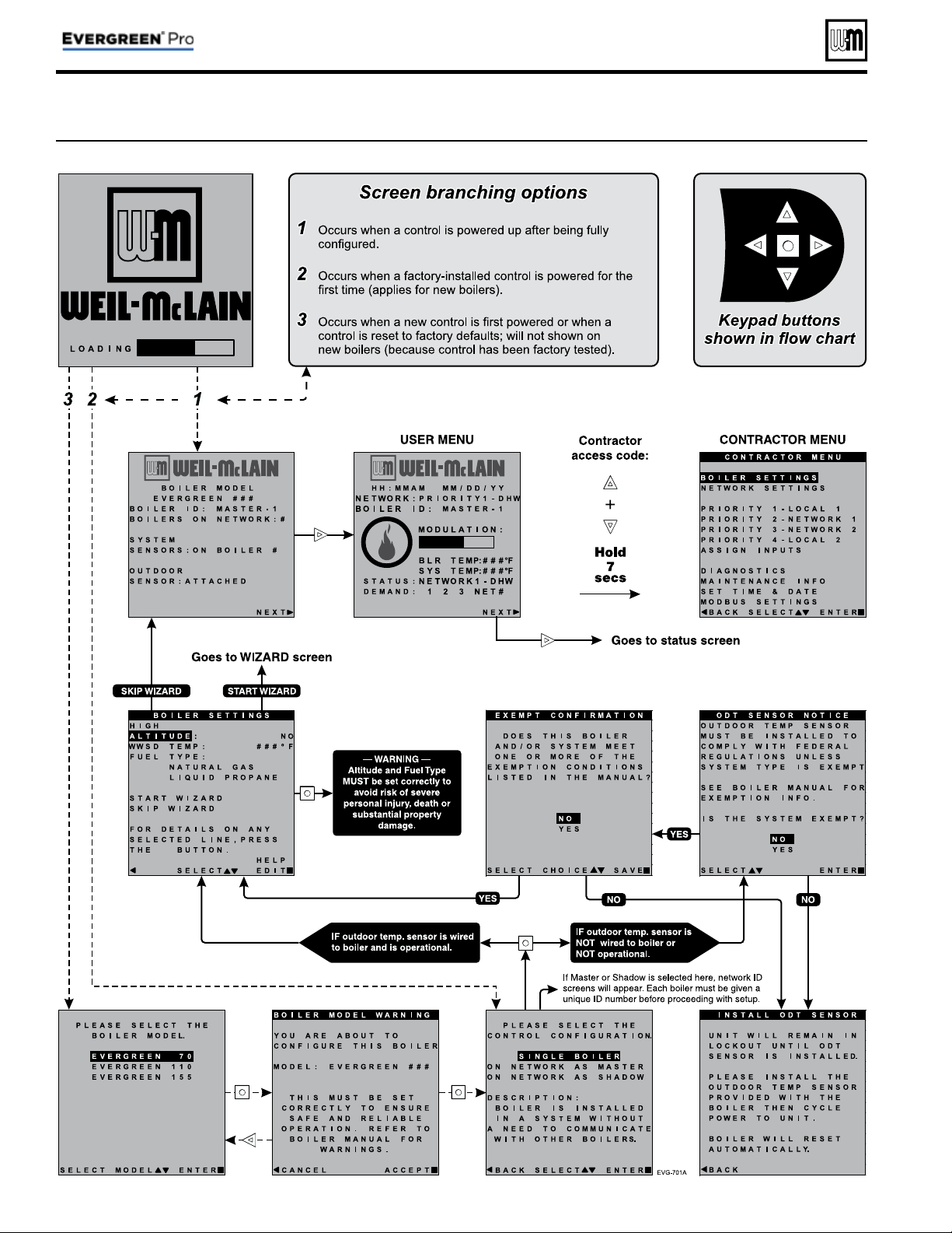
Figure 17 Initial navigation — Accessing CONTRACTOR menus (multiple-boiler screens shown)
Evergreen
®
Control — INITIAL SCREENS
Part number 550-100-214/1220
– 40 –
CONDENSING GAS BOILER — 110/155 Advanced Manual
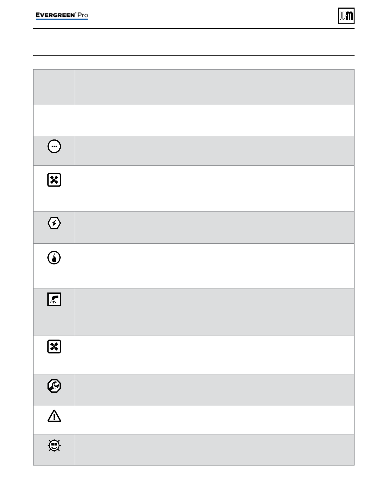
Part number 550-100-214/1220
– 41 –
CONDENSING GAS BOILER — 110/155 Advanced Manual
Figure 18 Control sequence of operation
Display
status
text
Control action
(also see Figure 19, page 42 )
POWER
UP
• Check the boiler model listed on the power-up screen. If it is not correct, turn off the boiler. See page 43 for in-
structions to change setting.
• When power is turned on, the screen lists sensors that are detected. If any sensor is not listed, make sure it is con-
nected correctly. Turn off power and restart.
Standby
• Standby - no calls for heat.
• Toggles through no dots, 1 dot, 2 dots, then 3 dots while in standby (wrench symbol will show instead if mainte-
nance is needed).
Blower
ON
• Call for heat detected.
• Display on with BLUE light (space heating) or PURPLE light (DHW).
• Start min/max timers if more than one system is calling - highest priority starts fi rst.
• Start circulators for this priority based upon settings.
• Calculate target temp — If sensor temp is below target temp, begin fi ring sequence.
• Blower to ignition speed for prepurge.
Ignition
• After prepurge times out, begin ignition cycle.
• Activate gas valve and ignition spark.
• Continue ignition spark for ignition period.
• Turn off spark and use electrode to check for fl ame signal.
Space
Heating
• Flame detected.
• Release boiler to modulation.
• NOTE: If fl ame is not detected, the gas valve is turned off, blower turns on (postpurge), and control starts cycle
again. After 5 failures, the control waits 60 minutes, then tries again.
• If priority timer times out, switch to next priority and start priority timer.
• If demand satisfi ed, go to postpurge.
DHW
Heating
• Flame detected.
• Release boiler to modulation.
• NOTE: If fl ame is not detected, the gas valve is turned off, blower turns on (postpurge), and control starts cycle
again. After 5 failures, the control waits 60 minutes, then tries again.
• If priority timer times out, switch to next priority and start priority timer.
• If demand satisfi ed, go to postpurge.
Blower
OFF
• Demand satisfi ed (temperature reaches target temperature or limit setting).
• Gas valve off.
• Blower to ignition speed for postpurge.
• Return to standby after purge.
Maintenance
• Display fl ashes BLUE, toggling between graphic screen and maintenance screen (occurs if maintenance schedule
timer times out).
• Will show during standby only.
• Boiler operates as normal.
Error/fault
• Display turns RED due to error or limit event.
• Flashing display means lockout condition.
WWSD
• Warm weather shutdown - the boiler will not be allowed to fi re on space heating if the outside temperature is
greater than the WWSD setting.
• DHW operation is not affected by WWSD.
Control operation
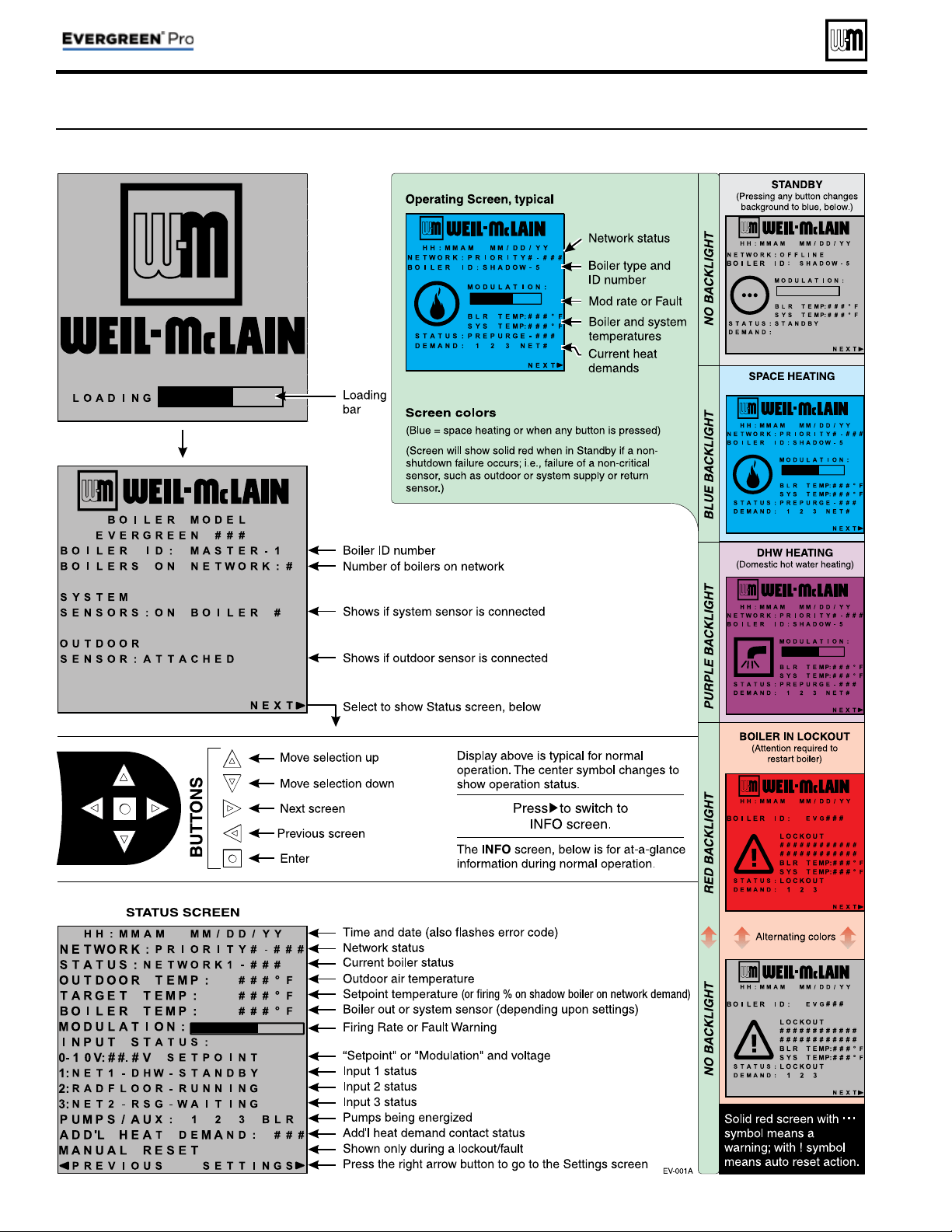
Part number 550-100-214/1220
– 42 –
CONDENSING GAS BOILER — 110/155 Advanced Manual
Control operation (continued)
Figure 19 Evergreen
®
control display screens and typical navigation – Advanced mode, multiple boilers
Part number 550-100-214/1220
– 43 –
CONDENSING GAS BOILER — 110/155 Advanced Manual
Menus and Items Default setting Range/options
BOILER SETTINGS Menu
( page 47 )
• BOILER MODEL
Factory set Evergreen
®
models available
• CONTROL TYPE
Single Single, Master or Shadow
• HIGH ALTITUDE
NO Yes or No
• LP GAS
No Yes or No
• ODT SENSOR EXEMPT
No Yes or No
• HIGH LIMIT TEMP
200°F 50 to 200°F
• WWSD TEMP
70°F OFF, 50–100°F
• ADJUST OUTDOOR
0°F -10 to +10°F
• CIRCULATOR EXERCISING
ALL ON ON or OFF for each circulator
• FREEZE PROTECT CIRCS
ONLY BOILER CIRCULATOR ON ON or OFF for each circulator
• RESET FACTORY DEFAULT
— —
PRIORITY menus
( page 52 ) Default setting Range/options
•
INPUTS ASSIGNED
Varies by priority 1, 2, 3
• SYSTEM TYPE
Varies by priority See Figure 21, page 45 for choices
• TARGET MOD SENSOR
Varies System Supply or Boiler Out
• TARGET ADJUST
Varies None, 0–10V, or ODT
• SUPPLY MAX
Varies 60 to 190°F
• SUPPLY MIN
Varies by system type 60 to 190°F
• OD RESET MAX
70°F 50 to 100°F
• OD RESET MIN
0°F -20 to 50°F
• VOLTS FOR MAX
10V 5V-10V
• VOLTS FOR MIN
0V 0V-4.9V
• BOOST TIME
OFF OFF, 1 to 240 minutes
• SYSTEM OFF DIFF
Varies (5 or 10°F) 2 to 15°F
• SYSTEM ON DIFF
10°F 2 to 15°F
• MAX BLR TEMP
Equals SUPPLY MAX 60 to 190°F
• ADD BLR DIFF
5°F 2 to 10°F
• DROP BLR DIFF
5°F 2 to 10°F
• MOD DELAY TIME
2 minutes 1 to 15 minutes
• STABILIZE TIME
5 minutes 3 to 30 minutes
• ADD DELAY TIMER
60 seconds 30 to 240 seconds
• DROP DELAY TIMER
60 seconds 30 to 240 seconds
• BOILER ON DIFF
5°F 2 to 20°F
• BOILER OFF DIFF
5°F 2 to 10°F
• MAX ON TIME
30 minutes OFF, 1 to 240 minutes
• MIN ON TIME
15 minutes OFF, 1 to 240 minutes
• RUN BOILER PUMP
Varies by system YES or NO
• RUN AUX PUMP/OUTPUT
Varies by system YES or NO
• PRE PUMP
OFF OFF, 1 to 240 seconds
• POST PUMP
30 seconds OFF, 1 to 240 seconds
• MAX RATE
(Local priorities only)
96% 100% to 21%
Figure 20 Evergreen
®
control settings available in ADVANCED MODE (see Boiler Manual for BASIC MODE settings)
See detailed information about controls settings (parameters) on the following pages.
Available control settings – Advance Mode
Part number 550-100-214/1220
– 44 –
CONDENSING GAS BOILER — 110/155 Advanced Manual
Menus and Items Default setting Range/options
•
MIN RATE
20% 20% to 99%
• MAX SYS MBH
(Network priorities only)
AUTO AUTO or 100 to 32,000 MBTU’s
• MIN BOILERS (Network priorities only)
1 1 to 8
• ACTIVATE CONTACT
(ADDITIONAL HEAT DEMAND)
OFF OFF, 1st, or 2nd
• RESPONSE TIME
(ADDITIONAL HEAT DEMAND)
OFF OFF, 1 to 240 minutes
NETWORK SETTINGS
( page 48 ) Default setting Range/options
•
CONTROL TYPE
— Single, Master, Shadow
• BOILER ADDRESS
— 1 to 8
• NET MAX ON TIME
30 Off, 1 to 240
• NET MIN ON TIME
15 Off, 1 to 240
• MAX RATE ON NET
96% 100% to 21%
• MIN RATE ON NET
20% 20% to 99%
ROTATION AND SEQUENCE
( page 49 ) Default setting Range/options
•
SEQUENCE TYPE
Smart Smart, Parallel, Series
• BASERATE HIGH
Auto Auto, 20% to 100%
• BASERATE LOW
20% 20% to 100%
• LEAD BOILER ROTATE
Total Hours
Off, By Boiler, Total Hours, Incremental Hours
• ROTATE FREQ
7
1-30, 60, 90, 120, 150, 180, 210, 240, 270,
300, 330, 365
• FORCE LEAD ROTATE
Ye s Yes, or No
• CURRENT ORDER
— Shows current rotation sequence
ASSIGN INPUTS
( page 56 ) Default setting Range/options
•
INPUT 1
Single boiler – PRIORITY 2
Master or shadow boiler – NETWORK 2
NONE or
Single boiler – PRIORITY 1, 2, or 3
Master or shadow boiler –
NETWORK PRIORITY 1 or 2 or
LOCAL PRIORITY 1 or 2
• INPUT 2
Single boiler – PRIORITY 2
Master or shadow boiler – NETWORK 2
• INPUT 3
Single boiler – PRIORITY 2
Master or shadow boiler – NETWORK 2
Diagnostics
(see Boiler Manual)
MAINTENANCE ( page 58 )
SET DATE AND TIME ( page 58 )
Figure 20 Evergreen
®
control settings available in ADVANCED MODE, continued
Available control settings – Advance Mode (continued)
See detailed information about controls settings (parameters) on the following pages.
Part number 550-100-214/1220
– 45 –
CONDENSING GAS BOILER — 110/155 Advanced Manual
Figure 21 System types available (each option provides factory presets for operating parameters)
System Type
8-Character
Abbreviation
3-Character
Abbreviation
Supply
Max °F
Max Blr
Temp °F)
OD Reset
Min °F
Supply
Min °F
OD Reset
Max °F
Run
Boiler
Pump
Run System
Pump/Aux
Fan-coil FAN-COIL
FCL 180 180 0 140 70 YES YES
Finned Tube Baseboard FIN BASE
FTB 180 180 0 130 70 YES YES
Cast Iron Baseboard IRONBASE
CIB 180 180 0 120 70 YES YES
Cast Iron Radiators RADIATOR
CIR 180 180 0 120 70 YES YES
Radiant - slab on grade RAD SLAB
RSG 120 120 0 80 70 YES YES
Radiant - thin slab RAD SLAB
RTS 140 140 0 80 70 YES YES
Radiant - below fl oor
(staple up)
RADFLOOR
RSU 160 160 0 90 70 YES YES
Radiant - above fl oor
(sleeper system)
RADFLOOR
RAF 140 140 0 90 70 YES YES
Domestic Hot Water DOMESTIC
DHW 180 180 N/A N/A N/A NO NO
Custom (user defi ned)
XXXXXXXX
(user input)
fi rst three
of user
input
180 180 0 70 70 YES YES
SYSTEM TYPE presets
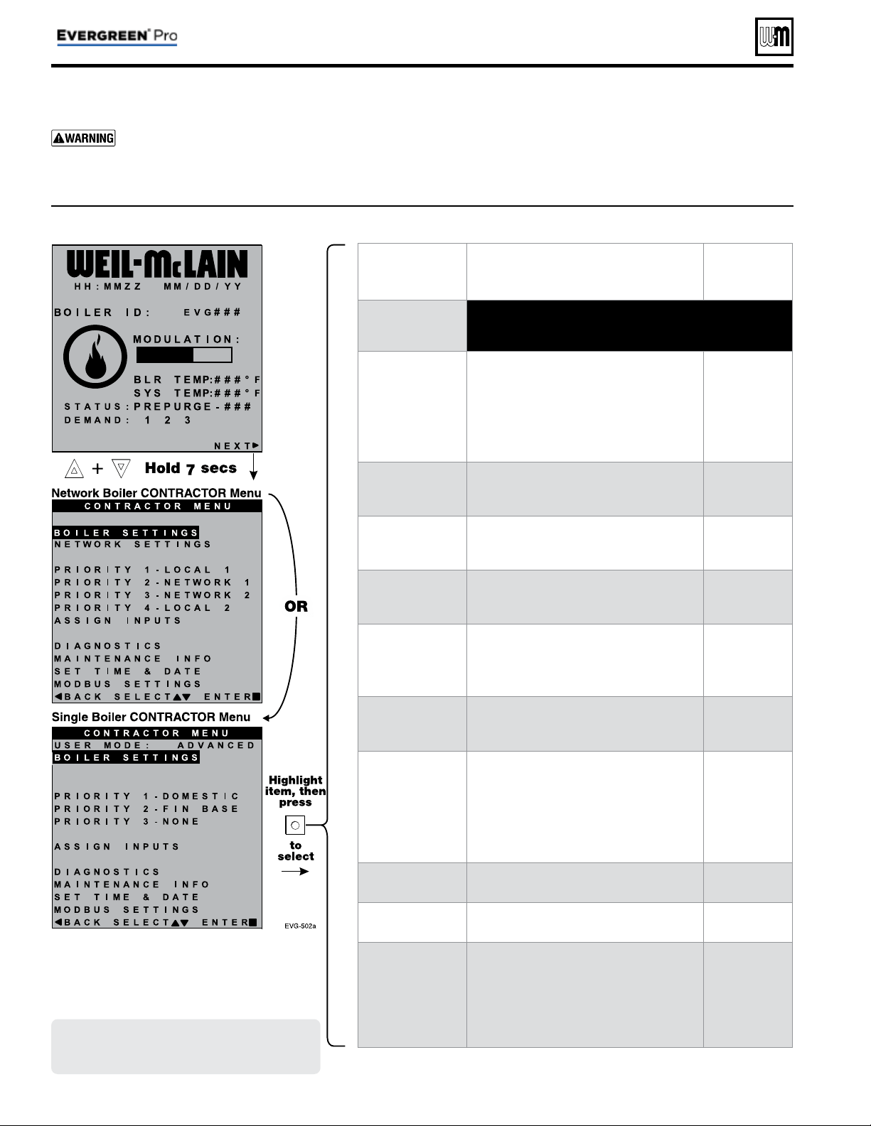
Part number 550-100-214/1220
– 46 –
CONDENSING GAS BOILER — 110/155 Advanced Manual
CONTRACTOR menus
Boiler Model, Altitude and Fuel Type are criti-
cal settings.
Failure to set correctly could result in
severe personal injury, death or substantial property
damage.
1. Access contractor menus by pressing and holding the UP and
DOWN arrow keys at the same time for 7 seconds.
2. See the following pages for explanations of control setting
options.
MENU ITEM PURPOSE
More
information
USER MODE
• Set this to ADVANCED to access single boiler advanced
settings. ADVANCED mode is automatic if configuring
network boilers.
BOILER SETTINGS
• Set/change boiler model, control type, high
altitude setting, gas type (L.P.), ODT sen-
sor requirement, manual reset, high limit
and WWSD temperature settings, outdoor
sensor temp adjustment, circulator exercis-
ing, freeze protection setup, and restore to
factory default option.
See page 47
PRIORITY 1
(LOCAL PRIORITY 1)
• These settings control operating tem-
peratures and behaviors for inputs that are
assigned to PRIORITY 1.
See page 52
PRIORITY 2
(NETWORK PRIORITY 1
or LOCAL PRIORITY 2)
• These settings control operating tem-
peratures and behaviors for inputs that are
assigned to PRIORITY 2.
See page 52
PRIORITY 3
(NETWORK PRIORITY 2
or LOCAL PRIORITY 3)
• These settings control operating tem-
peratures and behaviors for inputs that are
assigned to PRIORITY 3.
See page 52
PRIORITY 4
(LOCAL PRIORITY 2)
• Appears only on multiple boiler systems.
• These settings control operating tem-
peratures and behaviors for inputs that are
assigned to PRIORITY 4.
See page 52
ASSIGN INPUTS
• These settings assign Priority 1, 2, 3 or 4 to
each of the three inputs to the Evergreen
control.
See page 56
DIAGNOSTICS
• View error counters and historical informa-
tion including previous lockouts.
• View current status of temperatures, inputs,
outputs and runtimes; View network infor-
mation; View MODBUS communication
info; View software versions; Access manual
test mode screen; Initiate manual reset.
See
Boiler
Manual
MAINTENANCE
INFO
• Used to set contractor contact information,
boiler information and maintenance dates.
See page 58
SET TIME & DATE
• Use to set date and time — important since
fault occurrences are date/time stamped.
See page 58
MODBUS
SETTINGS
• Use to enter Modbus communications
information (enable/disable, range, parity
and stop bits, and baud rate).
• For Modbus addressing information, see
EVG Modbus Supplement.
See
EVG MODBUS
Supplement
Figure 22 Evergreen
®
control menu access — accessing CONTRACTOR men
Screens shown above are typical only.
Actual screens depend on control
settings chosen.
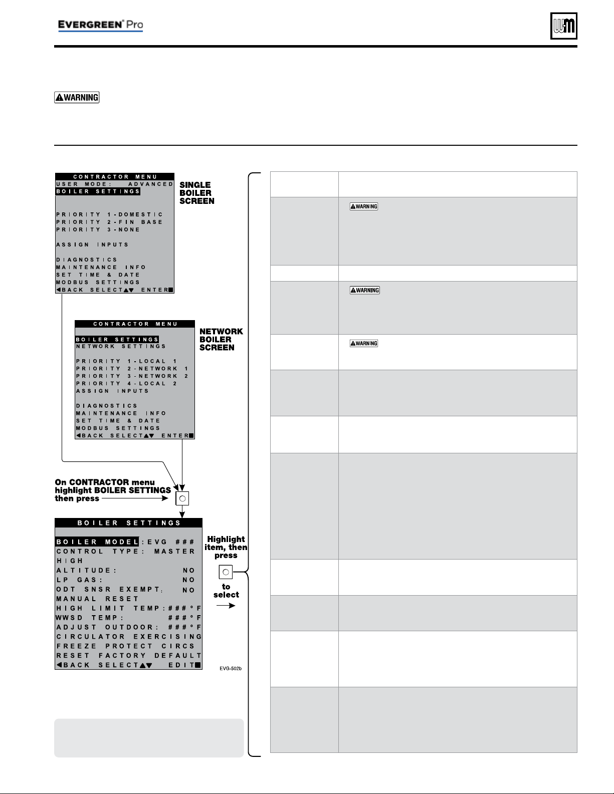
Part number 550-100-214/1220
– 47 –
CONDENSING GAS BOILER — 110/155 Advanced Manual
BOILER SETTINGS menu
MENU ITEM DESCRIPTION
BOILER MODEL
•
MUST be set to correct model.
• Check the boiler model against the model listed on the boil-
er’s rating plate. Change the selection to the correct model if
not. Also verify the model number on the Evergreen
®
display
at power-up. Failure to correct would result in severe per-
sonal injury, death or substantial property damage.
CONTROL TYPE
• Select single, master or shadow.
HIGH ALTITUDE
•
If the boiler is installed at an altitude above 5500 feet,
select YES for high altitude. The control will automatically adjust
fi ring rates (blower speeds) to compensate for altitude. Altitude
MUST be set correctly to avoid risk of severe personal injury, death
or substantial property damage.
LP GAS
•
MUST be correct — YES if LP Gas is used or NO
if natural gas is used. Follow screen instructions to change if
necessary.
ODT SENSOR
EXEMPT
• Select YES only if boiler is exempt from the requirement
for outdoor reset operation stipulated in Section 303 of the
2007 Energy Act. See information provided elsewhere in this
manual.
MANUAL RESET
HIGH LIMIT
TEMP
• If boiler outlet water temperature exceeds this temperature,
the Evergreen
®
control will shut down the boiler and enter
lockout. Changing this setting is NOT recommended.
WWSD TEMP
• WWSD stands for warm weather shutdown. It means the
boiler will not be allowed to fi re if the outside temperature is
greater than the WWSD setting.
When the boiler is kept off because the outside temperature is
above WWSD, the graphic display will show WWSD, and the
boiler will remain in standby until the outside temperature
drops below WWSD temperature.
WWSD does not apply to DHW systems.
The outdoor sensor must be installed to use this function.
Any setting other than OFF will cause the control to look for
a sensor. It will display an error if a sensor is not detected.
ADJUST
OUTDOOR
• Use this setting to calibrate the outdoor sensor when needed
to compensate for variations in lead length or other factors
that could affect total resistance in sensor circuit.
CIRCULATOR
EXERCISING
• For each circulator, select whether you want the control to
automatically start the circulator and run for 10 seconds for
each 72-hour period of inactivity.
FREEZE
PROTECT
CIRCS
• This function automatically starts the circulators chosen if the
heat exchanger sensors detect a temperature less than 45°F. In
addition, the burner is turned on if temperature drops below
40°F. Circulators and burner turn off when the temperature
rises above 48°F.
RESET
FACTORY
DEFAULTS
• Use this function to restore all control settings to factory
default values — will require complete restart and setup of
control after resetting. Record information from the MAIN-
TENANCE screen and any history information that may be of
use in the future. ALL stored data is eliminated when reset to
defaults, except for boiler model number.
Figure 23 Evergreen
®
ADVANCED mode BOILER SETTINGS options (see Figure 22, page 46 to access CONTRACTOR menu)
Boiler Model, Altitude and Fuel Type are criti-
cal settings.
Failure to set correctly could result in
severe personal injury, death or substantial property
damage.
1. Access contractor menus by pressing and holding the UP and
DOWN arrow keys at the same time for 7 seconds.
2. See Figure 22, page 46 for the screen sequences up to the
CONTRACTOR menu.
Screens shown above are typical only.
Actual screens depend on control
settings chosen.
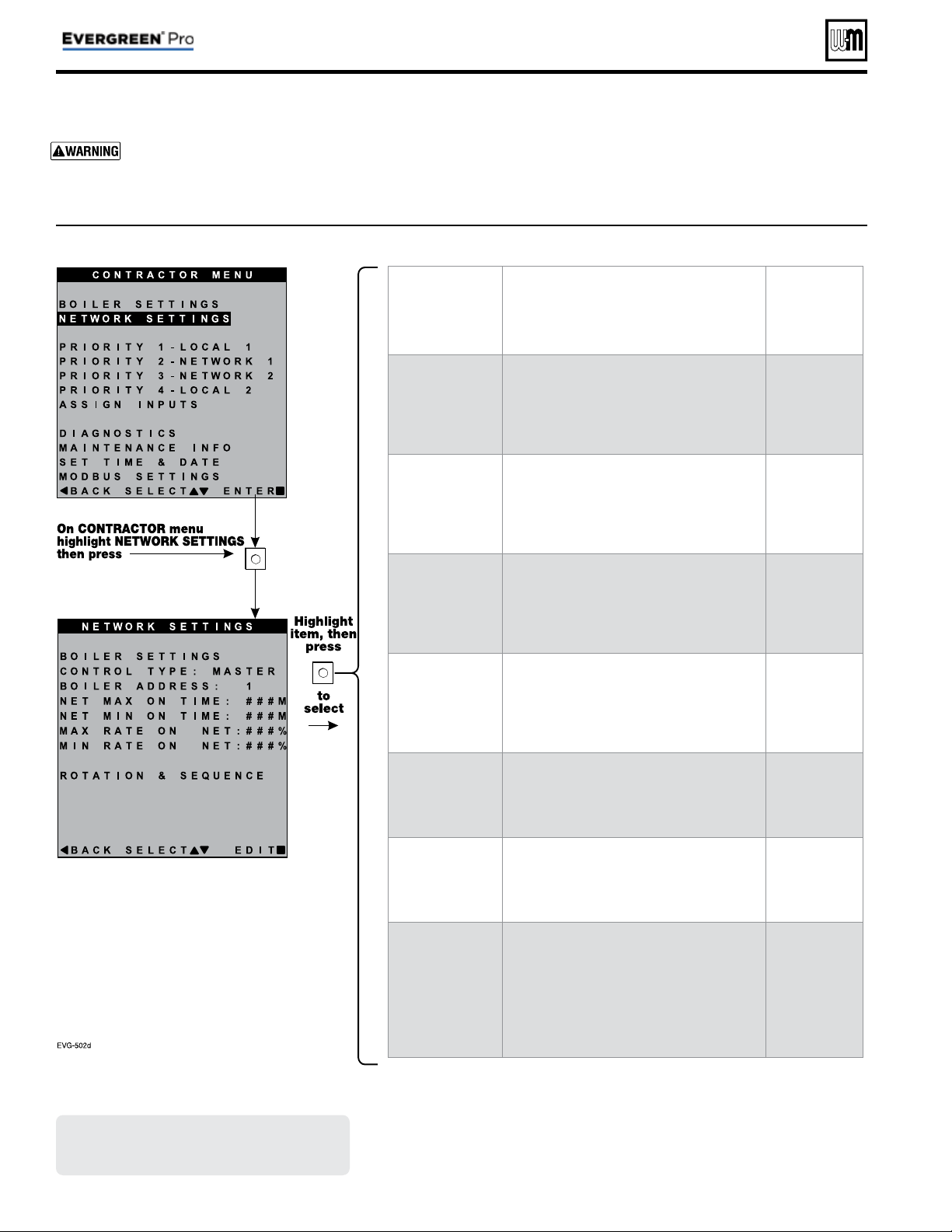
Figure 24 Evergreen
®
NETWORK SETTINGS menu (see Figure 22, page 46 to access CONTRACTOR menu)
Part number 550-100-214/1220
– 48 –
CONDENSING GAS BOILER — 110/155 Advanced Manual
NETWORK SETTINGS menu
Boiler Model, Altitude and Fuel Type are criti-
cal settings.
Failure to set correctly could result in
severe personal injury, death or substantial property
damage.
1. Access contractor menus by pressing and holding the UP and
DOWN arrow keys at the same time for 7 seconds.
2. See Figure 22, page 46 for the screen sequences up to the
CONTRACTOR menu.
MENU ITEM PURPOSE
More
information
CONTROL TYPE
• SINGLE, MASTER or SHADOW
• If another boiler has already been selected
as master, a notice window will appear if
MASTER is selected here.
None
BOILER
ADDRESS
• Network address of boiler (can be changed
here if desired, but every boiler must have a
unique address).
None
NET MAX ON
TIME
• Maximum amount of time this boiler will
operate on a network call for heat from the
Master boiler before switching to a LOCAL
PRIORITY 2 demand (if no LOCAL PRIOR-
ITY 1 demand is present).
None
NET MIN ON TIME
• Minimum amount of time this boiler will
operate on a network call for heat from the
Master boiler before switching to a LOCAL
PRIORITY 1 demand.
None
MAX RATE ON
NET
• Maximum rate the boiler will run at during
NETWORK calls.
None
MIN RATE ON
NET
• Minimum rate the boiler will run at during
NETWORK calls.
None
ROTATION &
SEQUENCE
• Select the method by which the boilers will
turn on and off.
• Choose between SMART, PARALLEL, or
SERIES. (This setting is only accessible on
Master boiler.)
See
Figure 26, page 50
for explanation of
sequencing options
Screens shown above are typical only.
Actual screens depend on control
settings chosen.
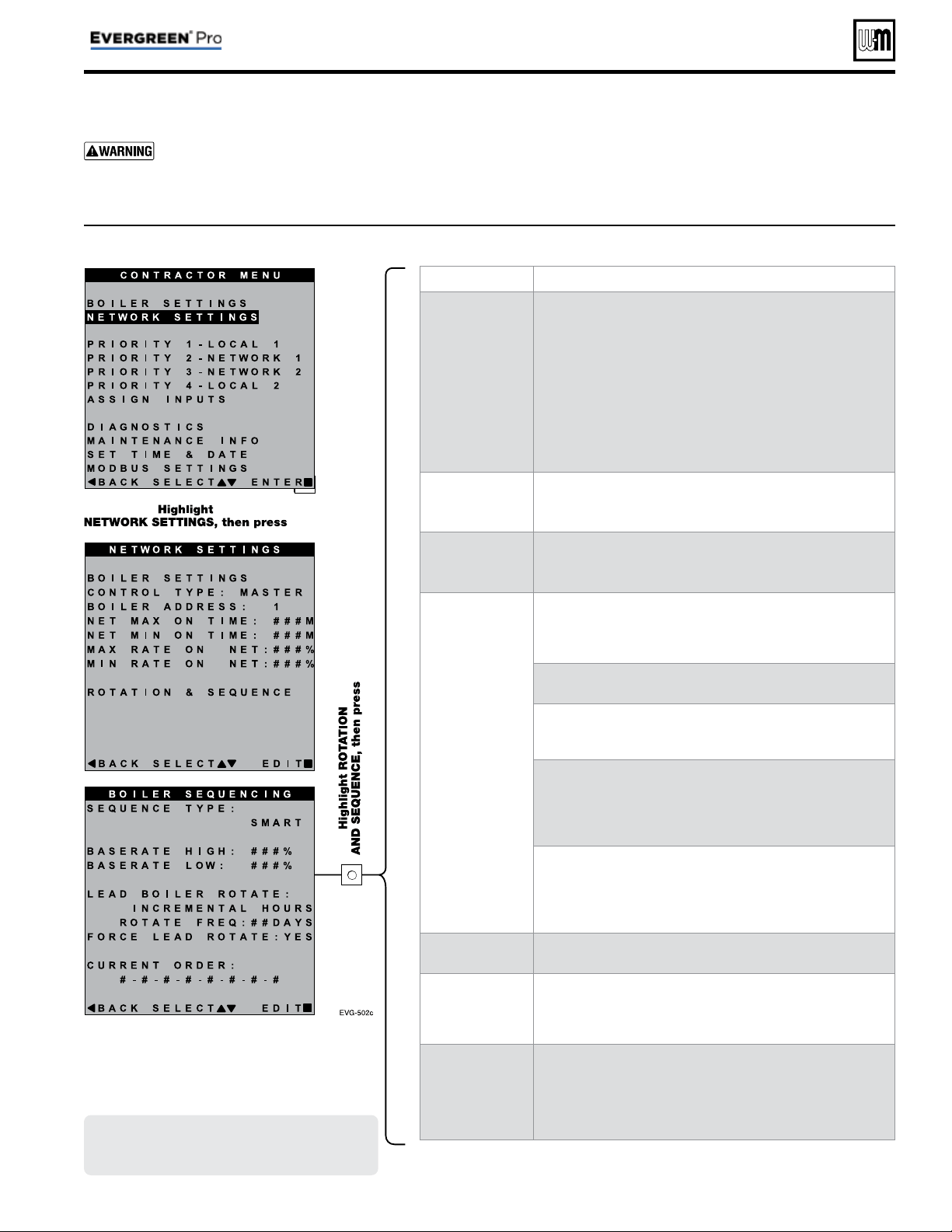
MENU ITEM PURPOSE
SEQUENCE TYPE
• Select the method of which the boilers will turn on and
off. Choose between SERIES, PARALLEL, or SMART.
SERIES sequencing allows each boiler to reach full input
before bringing on the next boiler in sequence. PARALLEL
sequencing uses a limiter, called BASERATE HIGH, to limit
the firing rate before adding additional boilers. SMART
sequencing (factory default setting) uses a low fi ring rate
setting, called BASERATE LOW, to keep boilers at a low fi ring
rate, bringing on additional boilers at reduced rate until all
boilers are on if necessary. Boilers are then allowed to modulate
together as high as necessary to meet demand.
BASERATE HIGH
• This sets highest modulation rate before turning on the next
boiler.
• This is read-only if in SMART mode.
BASERATE LOW
• This sets rate that the next boiler in sequence is going to turn
on when called.
• This is only visible if the Sequence Type is selected as SMART.
LEAD BOILER
ROTATE
• Choose how to rotate the boiler sequencing. Choose either
OFF, BY BOILER ID, TOTAL HOURS, or INCREMENTAL
HOURS. Firing sequence is changed every rotation period
(ROTATE FREQ – see setting explanation below).
• OFF — Master boiler is always the fi rst to fi re. Others fi re in
the order of their network ID.
• BY BOILER ID — Lead boiler toggles in the sequence of net-
work ID numbers (changes from boiler number 1 to number
2, then boiler number 2 to number 3, etc.).
• TOTAL HOURS — The boiler with the most lifetime oper-
ating hours is moved to the last in the fi ring sequence. The
boiler with the least lifetime operating hours is made fi rst in
the sequence. Others are ordered by their respective lifetime
operating hours.
• INCREMENTAL HOURS — Firing sequence is based on
the operating time during the previous rotation period.
The boiler with the least operating time is started fi rst; the
boiler with the most operating time is started last; all others
are started in order of their operating time.
ROTATE FREQ
• Recalculates the boiler order every ## days based on LEAD
BOILER ROTATE setting.
FORCE LEAD
ROTATE
• Select YES or NO. When the rotation frequency timer expires
and the new order is calculated, this forces off the boiler low-
est in the sequence. Then the boiler highest in the sequence
fi res to replace it.
Current Order
• Shows the current fi ring order of the boilers on the network.
• This list updates based on how many boilers are detected and
the order of sequence based on the above settings.
• Sequence is shown as left-most boiler is fi rst to turn on. Right-
most boilers are the fi rst to turn off.
Figure 25 Evergreen
®
NETWORK SETTINGS menu (see Figure 22, page 46 to access CONTRACTOR menu)
Part number 550-100-214/1220
– 49 –
CONDENSING GAS BOILER — 110/155 Advanced Manual
ROTATION AND SEQUENCE
Boiler Model, Altitude and Fuel Type are criti-
cal settings.
Failure to set correctly could result in
severe personal injury, death or substantial property
damage.
1. Access contractor menus by pressing and holding the UP and
DOWN arrow keys at the same time for 7 seconds.
2. See Figure 22, page 46 for the screen sequences up to the
CONTRACTOR menu.
Screens shown above are typical only.
Actual screens depend on control
settings chosen.
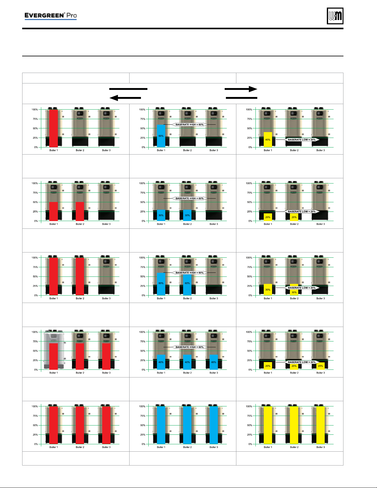
Figure 26 Evergreen
®
sequencing options — SMART, PARALLEL or SERIES (examples shown for 3-boiler network)
SERIES Sequencing PARALLEL Sequencing SMART Sequencing
Higher Part-Load Effi ciency
Quicker Boiler Response Time
STAGE 1 – Lead boiler modulates up to a maximum of 100% be-
fore turning on the next boiler in the sequence. The STABILIZE
TIME allows time for the boilers to modulate to meet system
demand before turning on additional boilers.
STAGE 1 – Lead boiler modulates up to a maximum of Base
Rate High before turning on the next boiler in the sequence.
The STABILIZE TIME allows time for the boilers to modulate
to meet system demand before turning on additional boilers.
STAGE 1 – Lead boiler modulates up to a low fi ring rate before
turning on the next boiler in the sequence. The STABILIZE TIME
allows time for the boilers to modulate to meet system demand
before turning on additional boilers.
STAGE 2 – Boiler #2 in sequence ignites and both boilers
modulate to so their combined energy output matches the energy
output of Boiler #1 at 100%. After a short MOD DELAY TIME,
the boilers will be released to modulate.
STAGE 2 – Boiler #2 in sequence ignites and both boilers
modulate to so their combined energy output matches the energy
output of Boiler #1 at Base Rate High. After a short MOD DELAY
TIME, the boilers will be released to modulate.
STAGE 2 – Boiler #2 in sequence ignites and both boilers modu-
late to BASE RATE LOW. After a short MOD DELAY TIME, the
boilers will be released to modulate.
STAGE 3 – Both boilers modulate up to a maximum of 100% be-
fore turning on the next boiler in the sequence. The STABILIZE
TIME allows time for the boilers to modulate to meet system
demand before turning on additional boilers.
STAGE 3 – Both boilers modulate up to a maximum of Base
Rate High before turning on the next boiler in the sequence.
The STABILIZE TIME allows time for the boilers to modulate
to meet system demand before turning on additional boilers.
STAGE 3 – Both boilers modulate up to a low fi ring rate before
turning on the next boiler in the sequence. The STABILIZE TIME
allows time for the boilers to modulate to meet system demand
before turning on additional boilers.
STAGE 4 – Boiler #3 in sequence ignites and then all boilers
modulate to so their combined energy output matches the energy
output of Boilers #1 and #2 at 100%. After a short MOD DELAY
TIME, the boilers will be released to modulate.
STAGE 4 – Boiler #3 in sequence ignites and then all boilers
modulate to so their combined energy output matches the energy
output of Boilers #1 and #2 at Base Rate High. After a short MOD
DELAY TIME, the boilers will be released to modulate.
STAGE 4 – Boiler #3 in sequence ignites and then all boilers
modulate to BASE RATE LOW. After a short MOD DELAY TIME,
the boilers will be released to modulate.
STAGE 5 – After all available boilers are fi ring, boilers are release
to modulate up to 100% of rate.
STAGE 5 – After all available boilers are fi ring, boilers are release
to modulate up to 100% of rate.
STAGE 5 – After all available boilers are fi ring, boilers are release
to modulate up to 100% of rate.
Part number 550-100-214/1220
– 50 –
CONDENSING GAS BOILER — 110/155 Advanced Manual
ROTATION AND SEQUENCE (continued)
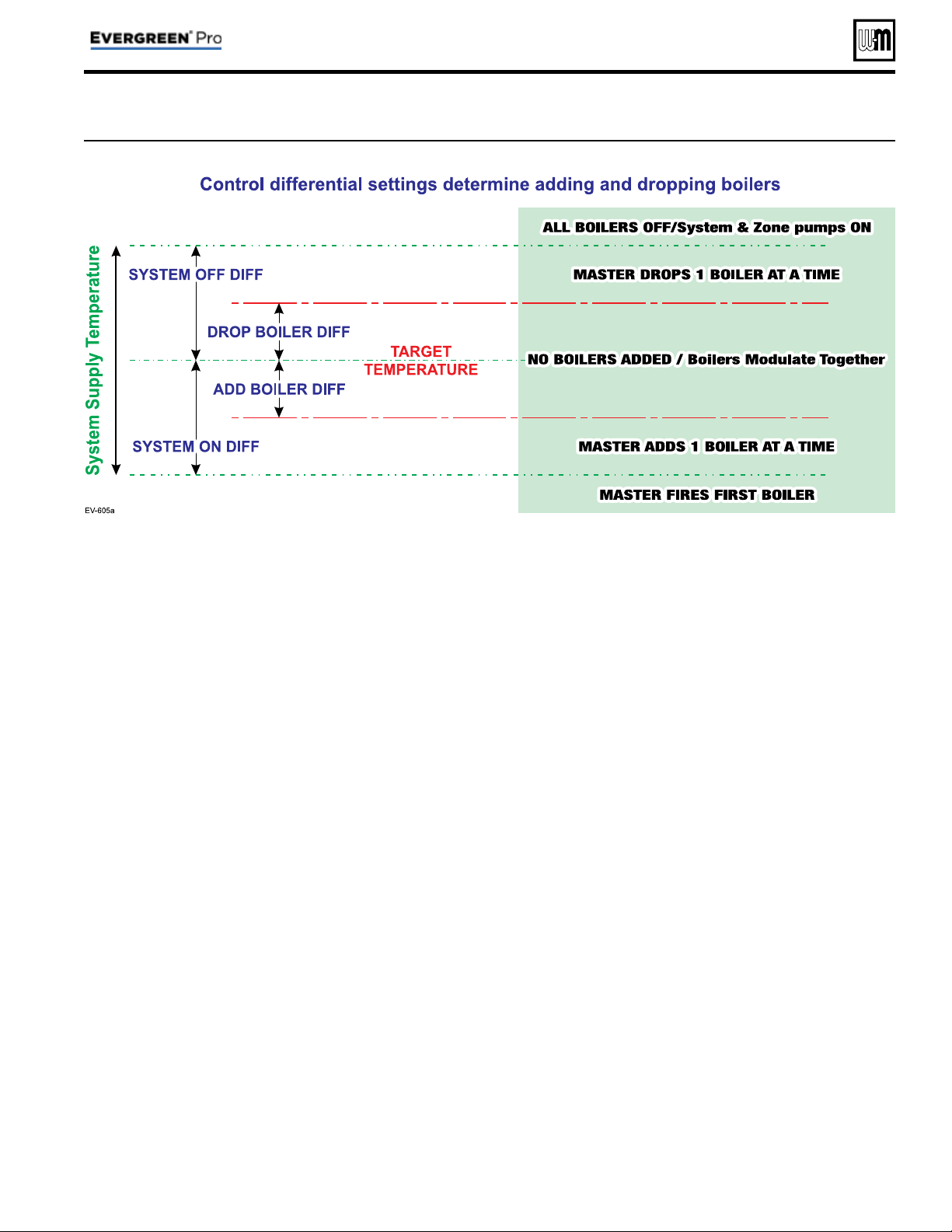
Figure 27 Boiler sequencing — adding and dropping boilers
Part number 550-100-214/1220
– 51 –
CONDENSING GAS BOILER — 110/155 Advanced Manual
ROTATION AND SEQUENCE (continued)
Figure 28 Evergreen
®
Network Boiler PRIORITY menus (access menus from CONTRACTOR menu
Local
Priority 1
Local
Priority 2
Network
Priority 1
Network
Priority 2
MENU ITEM DESCRIPTION
x x
INPUTS ASSIGNED
• List of inputs assigned to this priority/system on the local boiler (appears as 1, 2, 3).
x x x x
SYSTEM TYPE
• Select the system type for this PRIORITY, based on the heating terminal units in the
system. Use the CUSTOM selection to set the control for a different system type. The
factory preset values for SUPPLY MAX, SUPPLY MIN, OD RESET MAX and OD RESET
MIN are chosen based on the normal best setting for the terminal units. See page 45 .
x x
TARGET MOD
SENSOR
• Read only — shows whether boiler modulates based on System Supply sensor (network
priority) or Boiler Outlet sensor (local priority).
x x x x
TARGET ADJUST
• Select how target temperature is calculated by control: NONE (no reset, fi xed target
temperature), 0–10V (target temperature based on analog input from remote source),
ODT (outdoor reset operation).
x x x x
SUPPLY MAX
• Set SUPPLY MAX to the required supply water temperature for the system at design
maximum heat loss (typically 180°F for fi nned tube baseboard on new installations.)
x x x x
SUPPLY MIN
• SUPPLY MIN should equal the desired minimum supply water temperature for the
system. This line will not show if Target Adjust is selected as NONE.
x x x x
OD RESET MAX
• Appears if TARGET ADJUST is set to ODT. Outdoor temperature at which the target
temperature reaches its minimum value – usually set at the balance point temperature
for the building. (Does not appear if 0–10V or NONE is selected for Target Adjust.)
x x x x
OD RESET MIN
• Appears if TARGET ADJUST is set to ODT. Outdoor temperature at which the target
temperature reaches its maximum value – usually set at the outdoor design temperature
for the installation. (Does not appear if 0–10V or NONE is selected for Target Adjust.)
x x x x
VOLTS FOR MAX
• Appears if 0–10V is selected for Target Adjust. Set the voltage at which SUPPLY MAX
temperature is required.
x x x x
VOLTS FOR MIN
• Appears if 0–10V is selected for Target Adjust. Set the voltage at which SUPPLY MIN
temperature is required. For voltages between Min and Max, the target temperature
will be adjusted on a linear curve.
x x x x
BOOST TIME
• Every time the call for heat surpasses this duration of time the target temp will increase
(boost) up 10°F to a maximum temperature of SUPPLY MAX.
x x
SYSTEM OFF DIFF
• This is the amount the temperature must rise above system target to turn the boiler(s)
OFF.
x x
SYSTEM ON DIFF
• This is the amount the temperature must drop below system target to begin network
modulation routine. (This line may NOT appear, depending on TARGET ADJUST
setting.)
x x
ADD BLR DIFF
• If the system supply temperature has not reached target minus this differential at the
end of the STABILIZE TIME, the control will turn on the next available boiler in the
boiler fi ring order.
x x
DROP BLR DIFF
• If the system supply temperature rises to more than target plus this differential, the
control will turn off the last fi ring boiler in the boiler fi ring order. Drop Delay Timer
limits how quickly multiple boilers drop off.
x x
MOD DELAY TIME
• The time allowed for the boilers to adjust to the requested fi ring rate before beginning
Stabilize Time and resuming modulation.
x x
STABILIZE TIME
• The time allowed for all boilers actively heating a network priority to reach target modula-
tion rate requested by the master. If the timer expires and system temperature is less than
target – ADD BLR DIFF, the master will add the next available boiler. If there are no more
available boilers, the master will freely modulate the boilers to satisfy the heat demand.
x x
ADD DELAY TIMER
• Timer starts when the modulation rate of all boilers actively heating a network priority
are at BASE RATE HIGH, MAX RATE FOR NET, or are being self-limited. If the timer
expires and system temperature is less than target – ADD BLR DIFF, the master will add
the next available boiler.
x
x
DROP DELAY TIMER
• Minimum time before a boiler will be dropped off. This timer only begins after the fi rst
boiler has been dropped. It applies as each additional fi ring boiler is dropped.
Part number 550-100-214/1220
– 52 –
CONDENSING GAS BOILER — 110/155 Advanced Manual
Network Boiler PRIORITY menus
Boiler Model, Altitude and Fuel Type are criti-
cal settings.
Failure to set correctly could result in
severe personal injury, death or substantial property
damage.
1. Access contractor menus by pressing and holding the UP and
DOWN arrow keys at the same time for 7 seconds.
2. See Figure 22, page 46 for the screen sequences up to the
CONTRACTOR menu.
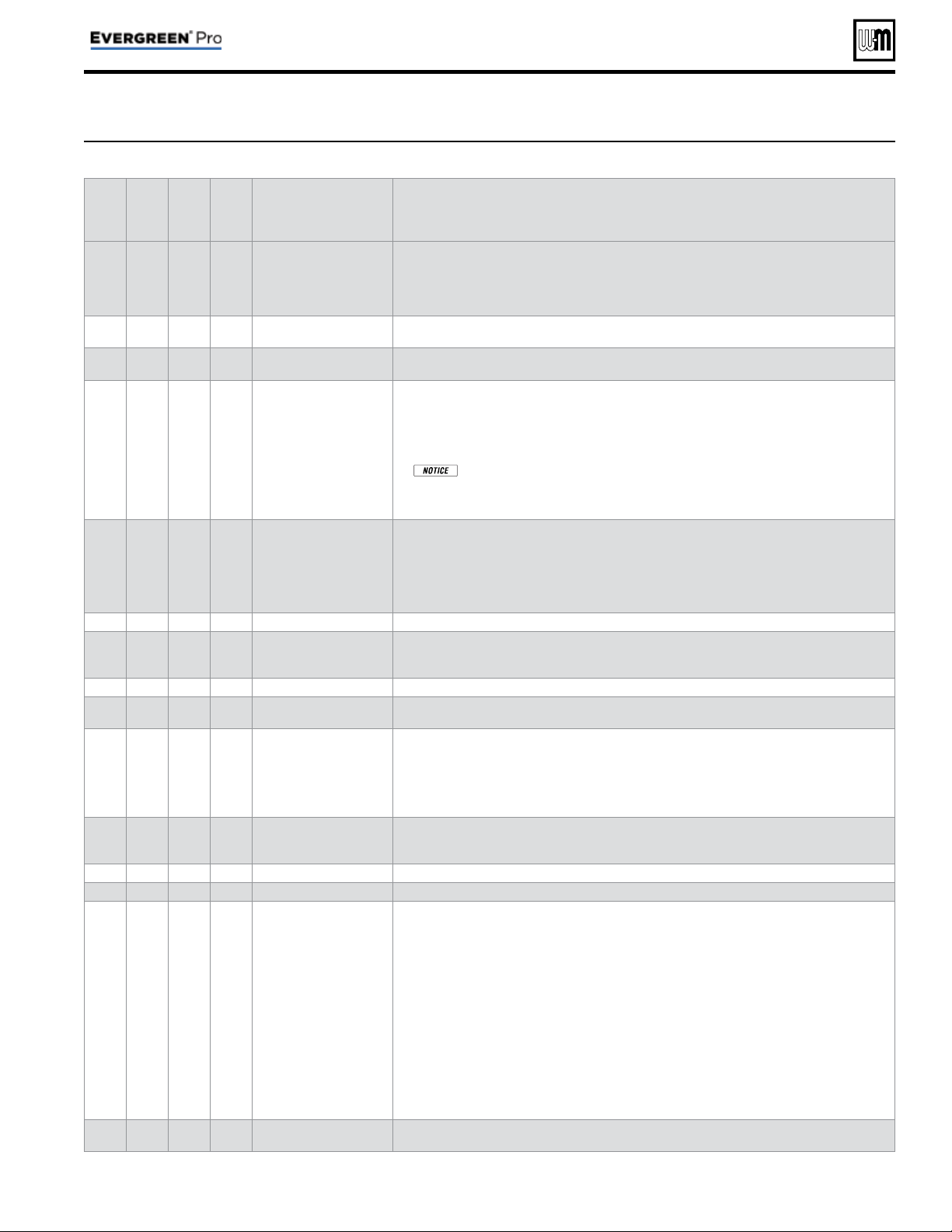
Local
Priority 1
Local
Priority 2
Network
Priority 1
Network
Priority 2
MENU ITEM DESCRIPTION
x x
MAX BLR TEMP
• If the boiler outlet temperature approaches [MAX BOILER TEMP – BOILER ON DIFF]
before the system supply temperature reaches its target, the control will modulate the
boiler based on the boiler outlet temperature. The boiler will cycle and modulate based
on the boiler ON and OFF differential settings. (This line does NOT appear if Target
Mod Sensor is set to Boiler Out).
x x x x
BOILER ON DIFF
• This is the amount the temperature must drop below target (or Boiler Max) to turn
the boiler ON.
x x x x
BOILER OFF DIFF
• This is the amount the temperature must rise above target (or Boiler Max) to turn the
boiler OFF.
x x
MAX ON TIME
• Maximum time boiler will run on this priority if it is being asked to run on another
priority. Will rotate among all priorities its being asked to run. Network boilers are also
controlled by NET MAX ON TIME (see Figure 24, page 48 ).
• NETWORK PRIORITY 1 only — Maximum time master will operate the network on
NETWORK PRIORITY 1 if NETWORK PRIORITY 2 is calling for heat.
•
When the master boiler detects a local call for heat from any boiler that is
currently operating for a network demand, the master control will allow that boiler
to switch to its local priority and replace the lost network energy of that boiler ap-
propriately.
x x
MIN ON TIME
• Minimum time the boiler will run on an existing priority before switching to a lower
priority, or back to an existing higher priority. If a new higher priority is called during
MIN ON TIME, the boiler will immediately switch to actively heat the higher priority.
Network boilers are also controlled by NET MIN ON TIME (see Figure 24, page 48 ).
• NETWORK PRIORITY 2 only — Minimum time master will operate on a network
priority 2 if network priority 1 is calling for heat.
x x
RUN BOILER PUMP
• Selects whether the Boiler Pump is turned on while running on this priority.
x x x x
RUN AUX PUMP/
OUTPUT
• When set to YES, input/output pairs on any network boiler assigned as AUX PUMP/
OUPUT -> ANY TT INPUT BY ITS PRIORITY, will activate. Set this to NO for priori-
ties that do not need this AUX PUMP/OUTPUT to be active.
x x x x
PRE PUMP
• Time associated PUMPS and AUX PUMP/OUTPUT are run before entering prepurge.
x x x x
POST PUMP
• Time associated PUMPS and AUX PUMP/OUTPUT are run after the call for heat has
ended and before switching to another call for heat.
x
x
MAX SYS MBH
• Limits the energy allowed by the boiler network to be put into this priority’s system.
The default is set to AUTO (the sum of all network boiler sizes). If the total size of the
boiler network is too large for a system, adjust MAX SYS MBH lower to the appropriate
energy. MAX SYS MBH can be set greater than AUTO if more Evergreen
®
boiler are
planned to be installed to the same network. This setting can be adjusted in 100 MBH
increments (100 MBH = 100,000 BTU/hours).
x
x
MIN BOILERS
• The Master turns on this many boilers in the network on an initial call for heat in order to
avoid delays due to accumulative wait times between boilers. When switching to another
network priority, MIN BOILERS is re-evaluated based on the other priority’s setting.
x x
MAX RATE
• Maximum rate this boiler will modulate up to while running on this priority.
x x
MIN RATE
• Minimum rate this boiler will modulate down to while running on this priority.
x x x x
ADD’L HEAT
DEMAND
ACTIVATE CONTACT
• If this is set to 1st: Immediately on a call for heat, the heat demand contacts close and
the RESPONSE TIME timer starts. If the call for heat from this demand is still active
at the end of the Response Time and the system has not reached [Target Temp - System
On Diff], the boiler system will start. If the system temperature is within this range,
the boiler system will not start unless the temperature drops below this value. The add'l
heat demand contact opens when the heat demand turns off.
• If this is set to 2nd: The boiler system starts immediately on a call for heat and starts the
RESPONSE TIME timer. If the call for heat is still active when the RESPONSE TIME
expires, the boiler will close its additional heat demand contact.
• Timers reset when priorities are switched.
• NETWORK PRIORITY 1 or 2 — The additional heat demand must be wired to the
master boiler.
• LOCAL PRIORITY 1 or 2 — The additional heat demand must be wired to the indi-
vidual boiler. A master boiler cannot use additional heat demand on a local priority.
x x x x
RESPONSE TIME
• Time to wait for system to respond before taking the Activate Contact action. If ACTI-
VATE CONTACT is OFF, this line does not appear.
Figure 28 Evergreen
®
PRIORITY menus, continued
Part number 550-100-214/1220
– 53 –
CONDENSING GAS BOILER — 110/155 Advanced Manual
Network Boiler PRIORITY menus (continued)
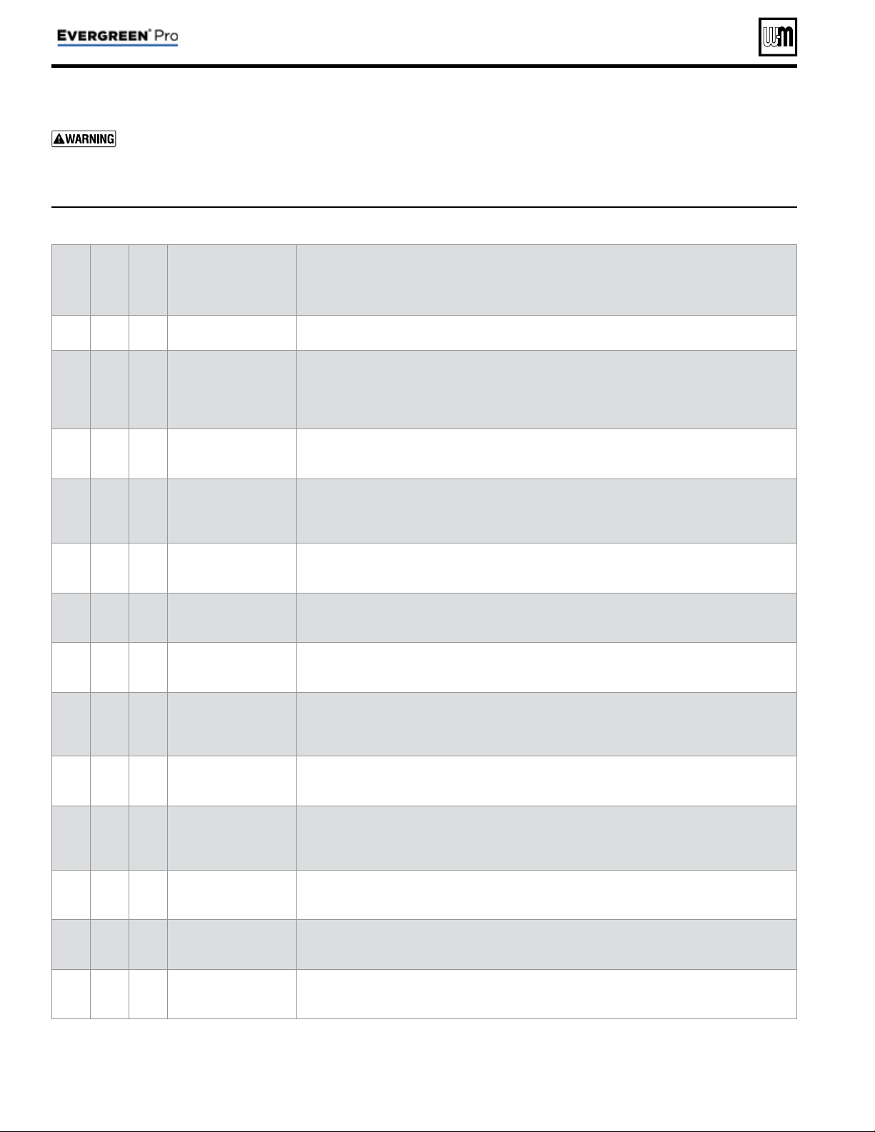
Figure 29 Evergreen
®
single boiler PRIORITY menus (access menus from CONTRACTOR menu
Priority 1
Priority 2
Priority 3
MENU ITEM DESCRIPTION
x x x
INPUTS ASSIGNED
• List of inputs assigned to this priority/system on the local boiler (appears as 1, 2, 3).
x x x
SYSTEM TYPE
• Select the system type for this PRIORITY, based on the heating terminal units in the system.
Use the CUSTOM selection to set the control for a different system type. The factory preset
values for SUPPLY MAX, SUPPLY MIN, OD RESET MAX and OD RESET MIN are chosen
based on the normal best setting for the terminal units. See page 45 .
x x x
TARGET MOD
SENSOR
• Select whether boiler modulates based on System Supply sensor or Boiler Outlet sensor.
x x x
TARGET ADJUST
• Select how target temperature is calculated by control: NONE (no reset, fi xed target tempera-
ture), 0–10VDC (target temperature based on analog input from remote source), ODT (outdoor
reset operation). This setting cannot be selected if system type is DHW.
x x x
SUPPLY MAX
• Set SUPPLY MAX to the required supply water temperature for the system at design maximum
heat loss (typically 180°F for fi nned tube baseboard on new installations.)
x x x
SUPPLY MIN
• SUPPLY MIN should equal the desired minimum supply water temperature for the system.
This line will not show if Target Adjust is selected as NONE.
x x x
OD RESET MAX
• Appears if TARGET ADJUST is set to ODT. Outdoor temperature at which the target tempera-
ture reaches its minimum value – usually set at the balance point temperature for the building.
x x x
OD RESET MIN
• Appears if TARGET ADJUST is set to ODT. Outdoor temperature at which the target tem-
perature reaches its maximum value – usually set at the outdoor design temperature for the
installation.
x x x
VOLTS FOR MAX
• Appears if 0–10V is selected for Target Adjust. Set the voltage at which SUPPLY MAX tem-
perature is required.
x x x
VOLTS FOR MIN
• Appears if 0–10V is selected for Target Adjust. Set the voltage at which SUPPLY MIN tempera-
ture is required. For voltages between Min and Max, the target temperature will be adjusted
on a linear curve.
x x x
BOOST TIME
• Every time the call for heat surpasses this duration of time the target temp will increase (boost)
up 10°F to a maximum temperature of SUPPLY MAX.
x x x
SYSTEM OFF DIFF
• This is the amount the temperature must rise above system target to turn the boiler OFF. (This
line does NOT appear if Target Mod Sensor is set to Boiler Out).
x x x
SYSTEM ON DIFF
• This is the amount the temperature must drop below system target to turn the boiler ON.
(This line does NOT appear if Target Mod Sensor is set to Boiler Out).
Part number 550-100-214/1220
– 54 –
CONDENSING GAS BOILER — 110/155 Advanced Manual
Single Boiler PRIORITY menus
Boiler Model, Altitude and Fuel Type are criti-
cal settings.
Failure to set correctly could result in
severe personal injury, death or substantial property
damage.
1. Access contractor menus by pressing and holding the UP and
DOWN arrow keys at the same time for 7 seconds.
2. See Figure 22, page 46 for the screen sequences up to the
CONTRACTOR menu.
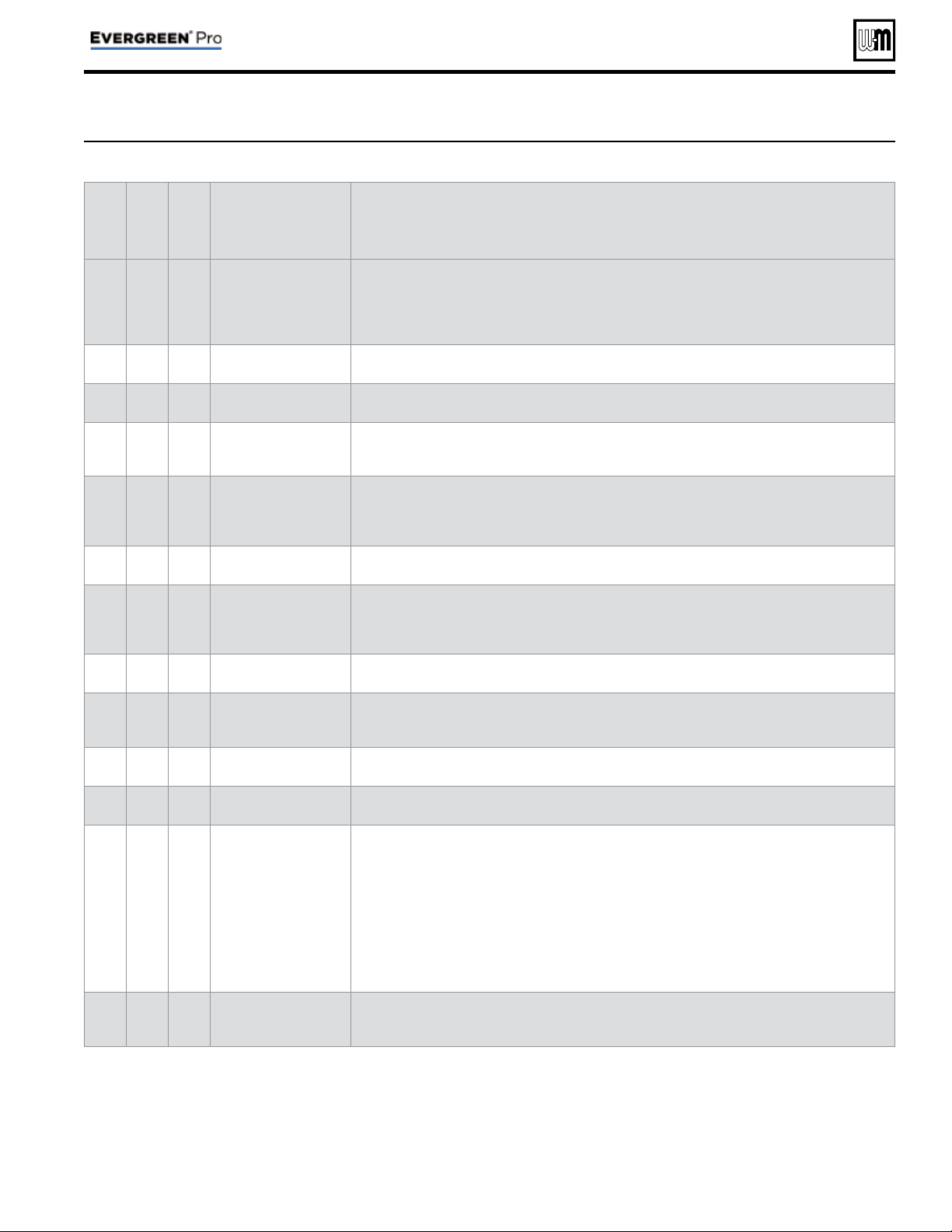
Priority 1
Priority 2
Priority 3
MENU ITEM DESCRIPTION
x x x
MAX BLR TEMP
• If the boiler outlet temperature approaches [MAX BOILER TEMP – BOILER ON DIFF] before
the system supply temperature reaches its target, the control will modulate the boiler based on
the boiler outlet temperature. The boiler will cycle and modulate based on the boiler ON and
OFF differential settings. (This line does NOT appear if Target Mod Sensor is set to Boiler Out).
x x x
BOILER ON DIFF
• This is the amount the temperature must drop below target to turn the boiler ON.
x x x
BOILER OFF DIFF
• This is the amount the temperature must rise above target to turn the boiler OFF.
x x
MAX ON TIME
• Maximum time this boiler will run on this priority if it is being asked to run on another prior-
ity. Will rotate among all priorities its being asked to run.
x x
MIN ON TIME
• Minimum time the boiler will run on an existing priority before switching to a lower priority,
or back to an existing higher priority. If a new higher priority is called during MIN ON TIME,
the boiler will immediately switch to actively heat the higher priority.
x x x
RUN BOILER PUMP
• Selects whether the Boiler Pump is turned on while running on this call for heat.
x x x
RUN AUX PUMP/
OUTPUT
• When set to YES, any input/output pairs assigned as AUX PUMP/OUPUT -> ANY TT INPUT
BY ITS PRIORITY, will activate. Set this to NO for priorities that do not need this AUX PUMP/
OUTPUT to be active.
x x x
PRE PUMP
• Time associated PUMPS and AUX PUMP/OUTPUT are run before entering prepurge.
x x x
POST PUMP
• Time associated PUMPS and AUX PUMP/OUTPUT are run after the call for heat has ended
and before switching to another call for heat.
x x x
MAX RATE
• Maximum rate this boiler will modulate up to while running on this priority.
x x x
MIN RATE
• Minimum rate this boiler will modulate down to while running on this priority.
x x x
ADD’L HEAT
DEMAND
ACTIVATE CONTACT
• If this is set to 1st: Immediately on a call for heat, the heat demand contacts close and the
RESPONSE TIME timer starts. If the call for heat from this demand is still active at the end
of the Response Time and the system has not reached [Target Temp – System On Diff], the
boiler system will start. If the system temperature is within this range, the boiler system will
not start unless the temperature drops below this value. The add'l heat demand contact opens
when the heat demand turns off.
• If this is set to 2nd: The boiler system starts immediately on a call for heat and starts the RE-
SPONSE TIME timer. If the call for heat is still active when the RESPONSE TIME expires, the
boiler will close its additional heat demand contact.
x x x
RESPONSE TIME
• Time to wait for system to respond before taking the Activate Contact action. If ACTIVATE
CONTACT is OFF, this line does not appear.
Figure 29 Evergreen
®
single boiler PRIORITY menus, continued
Part number 550-100-214/1220
– 55 –
CONDENSING GAS BOILER — 110/155 Advanced Manual
Single Boiler PRIORITY menus (continued)
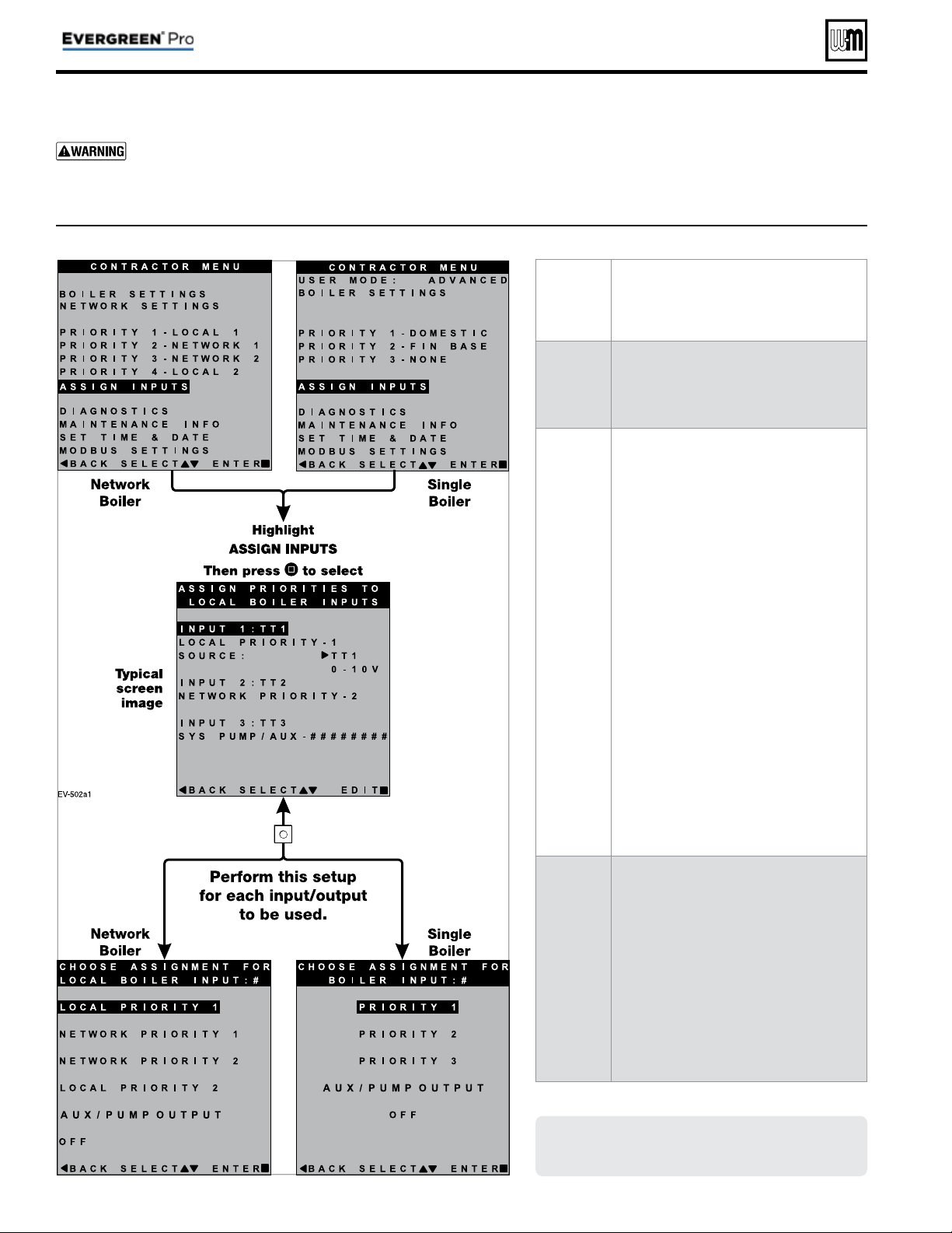
Part number 550-100-214/1220
– 56 –
CONDENSING GAS BOILER — 110/155 Advanced Manual
MENU
ITEM
PURPOSE
Overview
• There are three inputs/outputs available on
each boiler. This menu allows assignment
of which inputs/outputs operate which
priority/system.
INPUT 1
INPUT 2
INPUT 3
• See “EVG control Priorities & Input/
Outputs” on page 4 for an explanation of
priorities, inputs and outputs.
• Priority settings are adjustable. See page 52
through page 55 for priority options.
• The Assign Inputs menu is for designating
priorities to the correct inputs according to
the system installed.
• Multiple inputs can use the same priority.
• The Source line designates Input 1 as either
thermostat controlled or 0–10V controlled
for MODULATION. (On Master/Shadow
systems, this line is not present and Input
1 is predetermined as a thermostat-con-
trolled input.)
• When choosing 0–10V as the Source, a
NOTICE screen will pop up explaining
the use of the 0–10V input. Press SAVE to
use this option, or press cancel to return
the input to TT1.
AUX PUMP/
OUTPUT
• The AUX PUMP/OUTPUT function en-
ables an output to turn on in a variety of
selectable conditions.
• See page 57 for explanations and recom-
mended applications.
• In network boiler applications, outputs
assigned AUX PUMP/OUTPUT are con-
trolled by the master boiler, based on the
input/output and blower behaviors of all
boilers on the network.
Figure 30 Evergreen
®
Assign Inputs menu (see Figure 22, page 46 to access CONTRACTOR menu)
ASSIGN INPUTS menu
Boiler Model, Altitude and Fuel Type are criti-
cal settings.
Failure to set correctly could result in
severe personal injury, death or substantial property
damage.
1. Access contractor menus by pressing and holding the UP and
DOWN arrow keys at the same time for 7 seconds.
2. See Figure 22, page 46 for the screen sequences up to the
CONTRACTOR menu.
Screens shown here are typical only.
Actual screens depend on control settings
chosen.
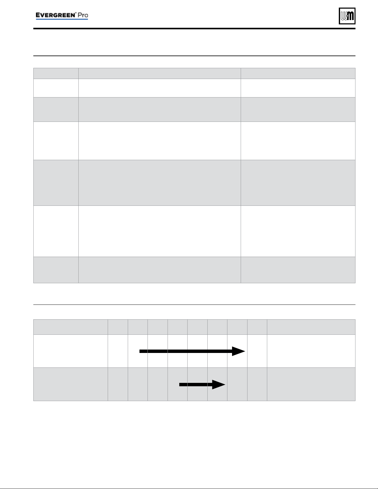
Figure 31
AUX PUMP/ OUTPUT
operation (accessed in ASSIGN INPUTS menu – see page 56 )
Option Activation conditions Suggested uses
ALWAYS ON
• Output is always energized whenever the control is powered.
• Hot loop for seasonal boilers that are manually
shut down at end of season and started up at
start of heating season.
EXTERNAL
SWITCH
• The output is energized on closure of an external switch wired to this
input and is de-energized when the external switch opens.
• Hot loop for boilers whose CH is manually
shut down at end of season and started up at
start of heating season, but remain available for
local calls (DHW, etc.).
OUTDOOR
BELOW WWSD
• This output is energized only when outdoor temperature is below the
WWSD setting (see BOILER SETTINGS menu, Figure 23, page 47 ).
• This setting is non-selectable if WWSD is set to OFF or ODT is not
connected at initial boiler power. If Outdoor Below WWSD is already
chosen and WWSD is later set to OFF, Outdoor Below WWSD will
behave as Always On.
• Hot loop for boilers whose CH is automati-
cally shut down based on outdoor temperature
(inferred heat loss), but remain on for local
calls (DHW, etc.).
ANY TT INPUT
• The assigned output is energized if there is an input closure on any of
the network boilers.
• The assigned output will de-energize once there are; no input closures
on any of the network boilers, post-purge has fi nished, and post-pump
time has expired.
• If the closed input is confi gured for a heat demand, its output will de-
energize after post-purge and post-pump.
• Energize a system pump relay if pump must
run during all heating calls.
ANY TT INPUT
BY ITS PRIORITY
SETTINGS
• The assigned output is energized:
• If there is an input closure on any of the network boilers.
AND . . .
• RUN AUX PUMP/OUTPUT is set to YES for the priority
assigned to the closed input.
• The assigned output will de-energize once there are; no input closures
on any of the network boilers, post-purge has fi nished, and post-pump
time has expired.
• Energize a system pump relay if pump must
run only on some heat calls (such as systems
with locally-connected DHW heating).
ANY BURNER
DEMAND
• The assigned output is energized when any boiler on the network
receives a call for heat and starts to pre-purge.
• The assigned output is de-energized once all burners are off and post-
purge is complete.
• Use for interlocking with combustion air
damper, fl ow switch, etc.
Figure 32 AUX PUMP/ OUTPUT operation — start, run and stop, based on boiler status
Option
Standby
TT
Closed
Pre-Pump
Pre-
Purge
Burner
Running
Post-
Purge
Post-
Pump
Standby
Comments
ANY TT INPUT
OR
ANY TT INPUT BY ITS
PRIORITY SETTINGS
off
ON
off
• See Figure 31 for explanation of
differences between the ANY TT
INPUT options.
ANY BURNER DEMAND
off off off
ON
off off
AUX PUMP/OUTPUT options
Part number 550-100-214/1220
– 57 –
CONDENSING GAS BOILER — 110/155 Advanced Manual
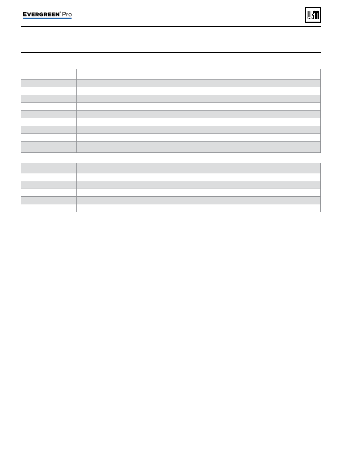
MAINTENANCE, DATE AND TIME menus
Figure 33 MAINTENANCE, DATE AND TIME menus — navigation (see Figure 19, page 42 for access information)
Part number 550-100-214/1220
– 58 –
CONDENSING GAS BOILER — 110/155 Advanced Manual
MAINTENANCE INFO
1. Use this section to enter contractor’s information, CP number, install date and to enter an automatic notice for maintenance
(default is 12 months). Because this shows on the display, it is an automatic means of notifying the homeowner of need for
scheduled maintenance by the technician. Select RESET REMINDER to reset for the next maintenance date.
SET TIME AND DATE
1. Enter current date and time. This allows correct maintenance reminder timing and provides date and time stamp for lockout
histories on ERROR screen in Diagnostic Menu.
Maintenance Info Comments
Name Contractor name to appear in maintenance reminders and during lockouts
Phone Contractor phone number
Model Displays the boiler model selected in the boiler setup
CP Number Enter the CP# of the boiler
Installed Enter the date the boiler was installed
Last Date Date automatically entered when Reset Reminder is chosen by contractor
Next Date Date automatically calculated when Reset Reminder is selected by contractor
Interval Settings Contractor selects maintenance reminder frequency based on service history
Reset Reminder Contractor selects this to update Last maintenance Date and Next Date. Homeowner uses this to ignore the reminder and update only the Next
Date.
Set Time and Date Comments
Ye a r Set year (homeowner or contractor)
Month Set month (homeowner or contractor)
Day Set day (homeowner or contractor)
Hour Set hour (homeowner or contractor)
Minute Set minute (homeowner or contractor)

Part number 550-100-214/1220
– 59 –
CONDENSING GAS BOILER — 110/155 Advanced Manual
Notes

60
CONDENSING GAS BOILER — 110/155 Advanced Manual