
Loading ...
Loading ...
Loading ...
Allowablevent/airpipematerials&lengths
1. The concentric termination kit must be purchased
separately.
Use only the vent materials and kits listed in
Figure24,page21. Provide pipe adapters if
specied.
2. Locate the termination such that the total air piping and
vent piping from the boiler to the termination will not
exceed the maximum length given in Figure23,page20.
3. is termination requires a 45-degree elbow that is not
supplied with the termination kit. e maximum vent/
air pipe lengths include allowance for this elbow.
For polypropylene applications, comply with
any additional requirements in the vent system
manufacturer’s instructions. Provide 4” PVC-
to-PP transition pieces at the boiler vent and
air connections. PP adapter must have smooth,
straight section of pipe to insert in to the boiler
vent and air connections and must t and seal
tightly. PP adapters with their own seal which
would interfere with the internal seal of the
boiler vent or air connections must not be
used. Refer to page117 for a list of compliant
adapters. Install a locking collar at every joint.
For AL29-4C vent pipe applications, comply
with any additional requirements in the vent
system manufacturer’s instructions. Provide a
4”PVC transition at the boiler vent connec-
tion. Air pipe must be PVC or CPVC. Provide
transition pieces to PVC at the vent and air pipe
termination connections.
4. For 4” to 3” transitions, must use appropriate vent
material. For polypropylene or stainless steel must use
approved suppliers transitions (EVG 220 only).
Determineterminationlocation
Locate the concentric vent/air termination using the fol-
lowing guidelines:
1. Wall penetration thickness between 0” to 24”.
2. e concentric vent/air assembly must terminate as
shown in these instructions.
3. e termination must comply with the clearances and
limitations shown in Figure25,page23.
4. Locate the termination so it is not likely to be damaged
by foreign objects, such as stones or balls, or subject to
buildup of leaves or sediment.
5. For Canadian installations, follow requirements of
Natural Gas and Propane Installation Code, CAN/CSA
B149.1 or B149.2 and a ULCS636 compliant vent kit.
Multiplevent/airterminations
1. When terminating multiple Evergreen
®
boilers, install the
concentric vent/air termination assemblies as described
in this manual.
All vent outlets must terminate at the same
height to avoid possibility of severe personal
injury, death or substantial property damage.
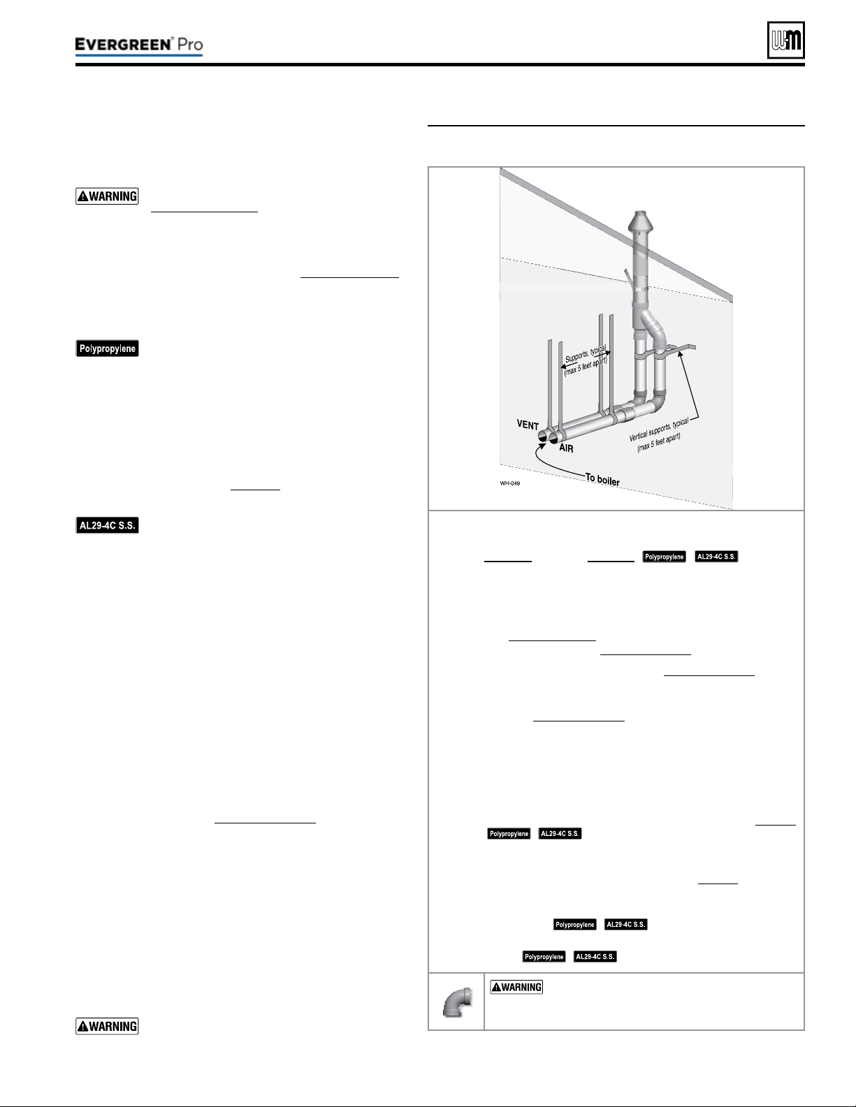
Figure39 INSTALLATIONSEQUENCE — Concentric vertical
Step1 Read and follow all instructions in this manual. DO NOT
proceedwithvent/airinstallationuntilyouhaveread
page19throughpage24.
See notices
at le.
Step2 Install the boiler in a location that allows proper routing of all
vent and air piping to the selected location.
Step3 Make sure the selected vertical termination location complies
with Figure25,page23. (Multiple boiler concentric terminations
must also comply with Figure40,page34.)
Step4 Use only the vent materials listed in Figure24,page21. Provide
pipe adapters where required.
Step5 Vent piping and air piping lengths must not exceed the values
shown in Figure23,page20.
Step6 e concentric termination must be assembled and installed
before piping from the boiler to the termination.
Step7 Prepare the vertical penetration(s) — assemble the concen-
tric termination kit and secure the penetration components
as instructed in this section. Provide the supports indicated
and mount the termination assembly. See “Prepare roof pen-
etrations” and “Mount concentric termination” on page34.
See notices at le.
Step8 Install vent and air piping between the boiler and the concentric
vent/air termination. Slope horizontal piping downward toward
the boiler at least 1/4 inch per foot. See page38 for general
guidelines.
Step9 Install pipe supports every 5 feet on both the horizontal and
vertical runs.
See notices at le.
Step10 Install a hanger support within 6inches of any upturn in the
piping.
See notices at le.
USESWEEPELBOWSFORALLVENTAND
AIR PIPING — DO NOT use short radius elbows
for vent or air piping. Boiler performance could be
aected.
Part number 550-100-211/0122
– 33 –
220 /29 9/3 00 /39 9
Loading ...
Loading ...
Loading ...