
Loading ...
Loading ...
Loading ...
Part number 550-100-211/0122
– 53 –
220 /29 9/3 00 /39 9
(see wiring diagram, Figure 65, page 59)(continued)
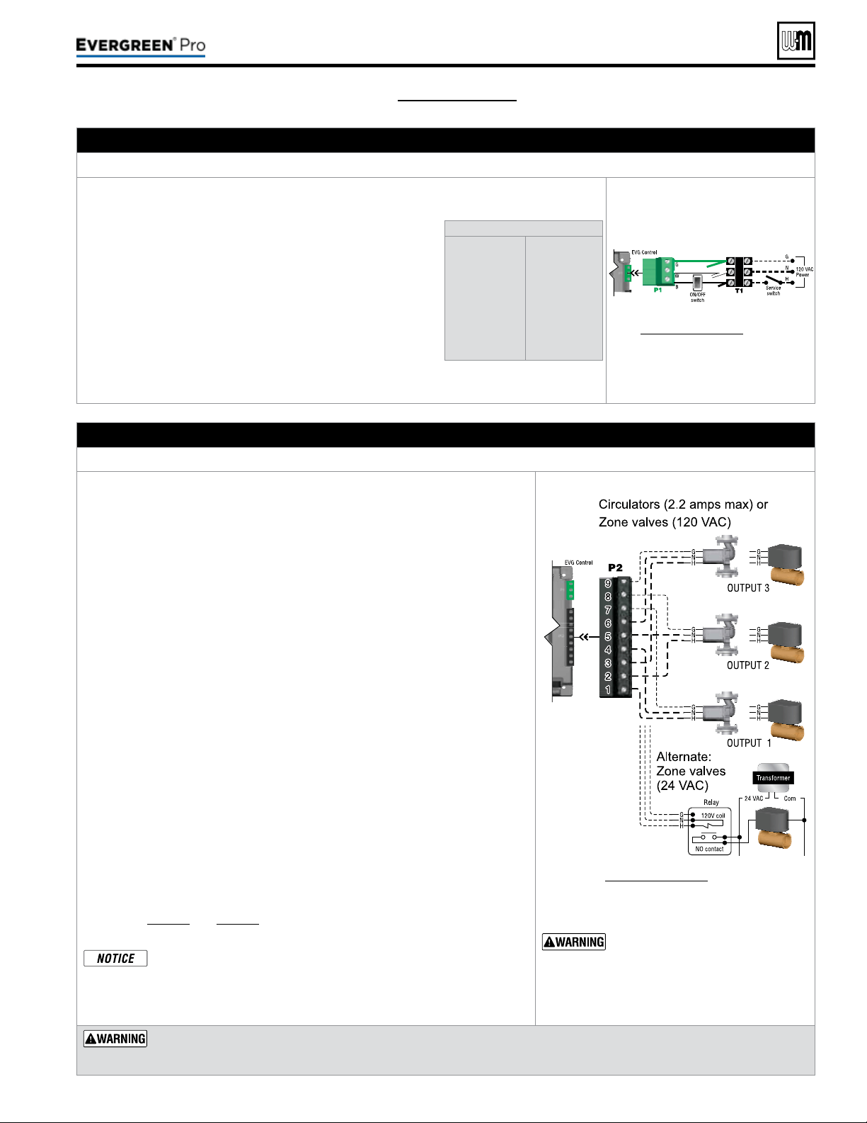
A. 120 VAC Power Supply – REQUIRED
TerminalBlockT1(control tray, right front)
1. Provide and install a properly-sized, fused disconnect or
service switch as required by applicable codes. (15-amp for
most cases.)
a. Use table at right to determine total load. Suggested
fused disconnect or service switch sizing is 15-amp if
total load is 12amps or less, 20-amp if total load is more
than 12amps.
2. Connect properly sized 120 VAC power wiring to Ever-
green
®
boiler line voltage terminal strip T1 as shown at right.
3. If possible, provide a surge suppressor in the supply power
line. is will reduce the possibilities of control damage due
to line surges.
4. Must wire ground to this terminal to provide boiler ground-
ing.
Determinetotalload
Boiler & boiler pump
(combined load)
Output 1 . . . . . . .
(2.2 amps max)
Output 2 . . . . . . .
(2.2 amps max)
Output 3 . . . . . . .
(2.2 amps max)
TOTAL . . .
. . . .
8.4 amps
____ amps
____ amps
____ amps
____ amps
See Figure65,page59 for details
B. 120VACOutputs1,2&3 – As needed for systems
TerminalStripP2(EVG control module, right side)
1. Output1: P2 Terminals 1 (H), 4 (N), 7 (G).
2. Output2: P2 Terminals 2 (H), 5 (N), 8 (G).
3. Output3: P2 Terminals 3 (H), 6 (N), 9 (G).
4. Maximum load: 2.2 amps (use relay if circulator load is higher). See WARN-
ING below.
5. ese three outputs (Output 1, Output 2, and Output 3) can provide 120VAC
to the following listed below.
y A zone
circulator.
y A system circulator.
y A DHW circulator (used to circulate through an indirect tank).
y An auxil
iary item that must be energized during an input call, such as
an air damper.
6. When using inputs/outputs for heat/DHW demands, each input (Input1,
Input2, and Input3) controls its respective 120VAC output (Output1, Out-
put2, and Output3). Outputs are energized only when BOTH conditions
below are met:
a. e corresponding input indicates a call for heat/DHW (i.e. contact
closure).
b. e PRIORITY assigned to the Input/Output pair is ACTIVE (i.e. the zone
may be calling but the pump won’t activate unless the boiler is currently
running on that system/priority).
7. When using the inputs/outputs for the AUX PUMP/OUTPUT function, the
output is controlled by selectable conditions set up in the control.
a. Use the AUX PUMP/OUTPUT function for devices such as system
pumps, combustion air dampers, and other auxiliary equipment to activate
when the boiler is on/running.
b. See page78 and page79 for more information on the setup and selection
of operating conditions.
ForPriorityDHWApplication:
e DHW aquastat can be connected to any one of the three input/
output pairs. e selected input should be assigned to PRIORITY1
during the WIZARD setup or manually in the ASSIGN INPUTS
menu.
See Figure65,page59 for details.
Output circuits are 120 VAC. If
an output is to operate a low
voltage circuit or must be an
isolated contact, use an isola-
tionrelay.
CIRCULATORPOWER — Themaximumallow-
ablecurrentforeachcirculatoris2.2amps
at120VAC
.
For circulators with higher amp ratings, install a circulator relay
or starter. Connect only the 120-VAC coil to the Evergreen
circulator terminals.
Loading ...
Loading ...
Loading ...