
Loading ...
Loading ...
Loading ...
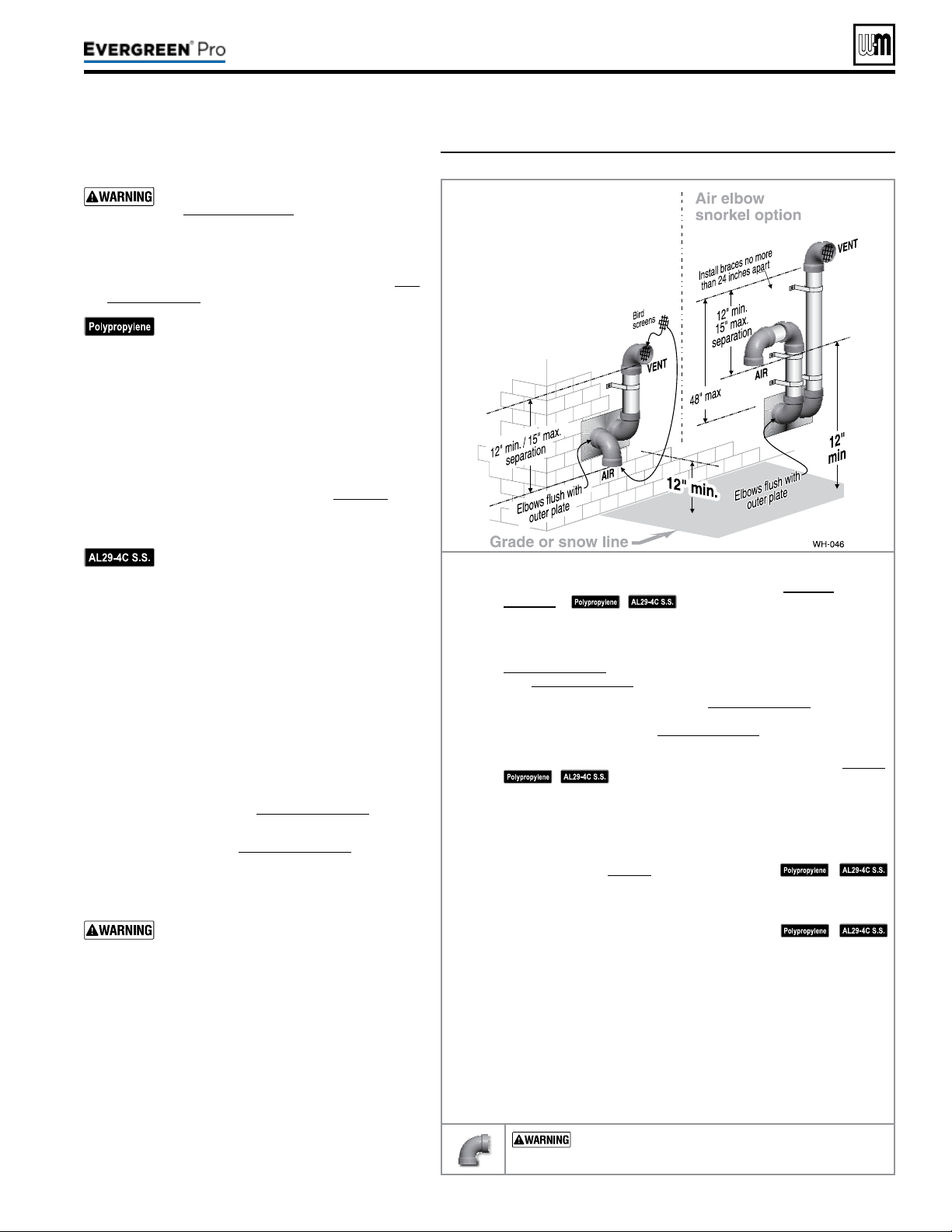
Figure27 INSTALLATIONSEQUENCE — Separate pipes sidewall
Part number 550-100-211/0122
– 25 –
220 /29 9/3 00 /39 9
DIRECT VEN T
Step1 Read and follow all instructions in this manual. DONOTproceed
withvent/airinstallationuntilyouhavereadpage19through
page24.
See notices at le.
Step2 Install the boiler in a location that allows proper routing of all vent and
air piping to the selected sidewall location.
Step3 Make sure the selected sidewall termination location complies with
Figure25,page23. (Multiple boiler sidewall plates must also comply
with Figure28,page26.)
Step4 Use only the vent materials listed in Figure24,page21. Provide pipe
adapters where required. Vent piping and air piping lengths must not
exceed the values shown in Figure23,page20.
Step5 Prepare the sidewall penetrations and secure the sidewall plates as
instructed in this section. See “Prepare wall penetrations” on page26.
See notices at le.
Step6 e air piping must terminate in a down-turnedelbow as shown
above. e vent piping must terminate in an elbowpointedoutward
orawayfromtheairinlet as shown above. See illustration above.
Step7 Install vent and air piping between the boiler and the sidewall open-
ings. Slope horizontal piping downward toward the boiler at least 1/4
inch per foot. See page38 for general guidelines.
See notices at le.
Step8 Install pipe supports every 5 feet on both the horizontal and vertical
runs. Install a hanger support within 6inches of any upturn in the pip-
ing, or per vent pipe manufacturer’s instructions.
See notices at le.
Step9 Attach the vent termination exterior piping: Use either of the congura-
tions shown above, as needed to ensure clearance above grade or snow line.
Keep vents/air intake area clear of accumulating snow.
Step10 e vent and air pipes may run up as high as 4 feet with no enclosure.
e vent and air pipes must be secured with braces, and all clearances
and lengths must be maintained. Space braces no further than 24
inches apart.
Step11 External venting greater than 4 feet requires an insulated enclosure
around the vent and air pipes. e vent and air terminations must exit
through the enclosure as shown in the illustration above, maintaining
all required clearances.
USE SWEEPELBOWS FORALL VENTAND AIR
PIPING — DO NOT use short radius elbows for vent or air
piping. Boiler performance could be aected.
Allowablevent/airpipematerials&
lengths
Use only the vent materials and kits listed
in Figure24,page21. Provide pipe adapt-
ers if specied.
1. Locate the termination such that the total air piping
and vent piping from the boiler to the termination
will not exceed the maximum length given in Fig-
ure23,page20.
For polypropylene applications, comply
with any additional requirements in the
vent system manufacturer’s instructions.
Provide 4” PVC-to-PP transition pieces
at the boiler vent and air connections. PP
adapter must have smooth, straight sec-
tion of pipe to insert in to the boiler vent
and air connections and must t and seal
tightly. PP adapters with their own seal
which would interfere with the internal
seal of the boiler vent or air connections
must not be used. Refer to page117 for a
list of compliant adapters. Install a locking
collar at every joint.
For AL29-4C vent pipe applications,
comply with any additional requirements
in the vent system manufacturer’s instruc-
tions. Provide a 4”PVC transition piece at
the boiler vent connection. e air piping
must be PVC or CPVC. Provide a 4”PVC
transition piece at the boiler air connec-
tion if using 3” air piping.
2. For 4” to 3” transitions, must use appropriate vent
material. For polypropylene or stainless steel must
use approved suppliers transitions (EVG 220 only).
Determineterminationlocation
1. Wall penetration thickness between 0” to 24”.
2. e air and vent terminations must be installed as
shown in Figure27 and Figure29,page26.
3. e terminations must comply with clearances and
limitations shown in Figure25,page23.
4. Locate the terminations so they are not likely to be
damaged by foreign objects, such as stones or balls,
or subject to buildup of leaves or sediment.
Do not exceed the maximum lengths
of the outside vent piping shown in
Figure27. Excessive length exposed to the
outside could cause freezing of condensate
in the vent pipe, resulting in potential
boiler shut down. In extremely cold cli-
mates, install an insulated chase around
the vent piping, particularly if using
longer lengths. e chase must allow for
inspection of the vent pipe, and insulation
must be protected from water.
Multiplevent/airterminations
1. When terminating multiple Evergreen
®
boilers,
terminate each vent/air connection as described in
this manual.
Loading ...
Loading ...
Loading ...