
Loading ...
Loading ...
Loading ...
Part number 550-100-211/0122
– 109 –
220 /29 9/3 00 /39 9
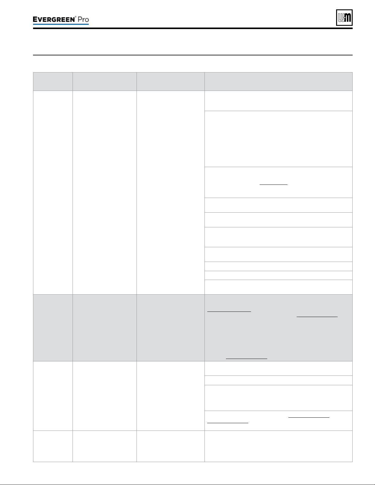
Figure105 Troubleshooting suggestions for Evergreen
®
boilers — Faultdisplays,diagnosticsandcorrectiveactions
(continued)
Display
Condition Diagnostics Corrective Action(s)
IGNITION
FAU LT
Boiler went through 5
ignition attempts and never
detected ame or ame
sense value never reached
minimum threshold for
boiler model.
Automatically resets after
1 hour or can be reset by
performing manual reset on
boiler.
Check condensate trap for blockage allowing condensate to
accumulate inside heat exchanger.
Check ignition cable connection.
Fouled, worn, bent, or faulty igniter.
Fouled igniters can be cleaned for additional use with steel wool.
Worn or badly fouled igniters should be replaced with the proper
repair part.
Igniter rods should be parallel with a 3.5 mm (0.138 in) spark gap.
NOTICE: Thin white deposits on the igniter are typical, but brown
or black deposits could be the result of ue gas recirculation.
Thoroughly inspect the venting system and termination for the
possibility of leakage or ue gas feedback into the air line.
Dirty burner and/or heat exchanger will cause high back pressure
and poor ignition.
Follow procedure in the Maintenance section of this manual to
clean burner and heat exchanger. Visual inspection of ueways
may not be sufcient to diagnose condition.
Check combustion settings on high and low re and adjust per
setup instructions if necessary.
Check incoming gas pressure with boiler off and at high re.
Adjust within limits on rating label.
Verify correct boiler model and altitude is selected in control and
correct elevation must be entered when operating above 2,00
feet.
Check ignition cable resistance. Should measure 1000 Ohms
(+/- 50 Ohms).
Check for ue pipe and intake pipe restrictions or blockage.
Check burner fasteners and gaskets.
Check venturi gaskets and proper venturi. (Propane models use
different venturi’s).
OUTDOOR
SENSOR ERROR
Outdoor temperature
sensor short or OPEN.
Will automatically reset if the
condition clears.
Warning only. Supply Max is
targeted until ODT is
restored, if used for target
adjustment.
Determine which sensors are suspect and measure their
resistance value and compare it to the values shown in
Figure 99, page 103. If the resistance values are incorrect
replace the temperature sensor. Refer to Replacement parts for
proper part number.
Check wire harness for loose connections and pin engagement
at sensor connection, chassis mount connection through control
housing, and the control. Unplug connection at sensor and at
control and check continuity between ends.
If problem persists after checking items above, replace control.
Refer to Replacement parts for kit number.
AIR PRESSURE
Switch Open
Occurs when Air Pressure
connection is open.
Reset using Manual Reset
screen on display.
High pressure in the exhaust
pipe or high vacuum in the
boiler intake or cabinet has
caused the air switch to
open. The switch is closed in
normal operating conditions.
Check boiler size selected in control against boiler rating label.
Correct if necessary to select the proper boiler size.
Check exhaust and intake pipe for restrictions or blockage.
Check condensate drain for blockage. If condensate is unable
to drain out of the boiler it can begin to block the ow of exhaust
gases. Clean the condensate collection area of the base and
condensate trap. Rell trap with fresh water.
Check the P7 connection as seen on Figure 65, page 59 &
Figure 66, page 60. Check the connections on the pressure
switch.
Closure Switch
fault
Proof of Closure
connections on P7 Pins 2
and 3 are open.
Soft lockout for 3½
minutes boiler retries. Each
consecutive failure adds 1
minute to lockout time, up to
6½ minutes maximum.
None - Check jumper on correct pins and secure connection.
Flow switch attached - Check correct pump is on, check wiring to
ow switch, and check switch is closing CAD - Check voltage to
damper. Check damper is opening.
Loading ...
Loading ...
Loading ...