
Loading ...
Loading ...
Loading ...
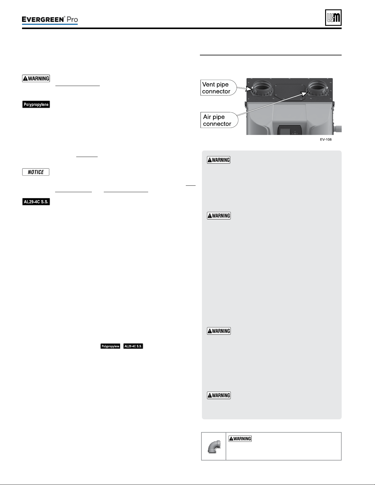
Figure46 Boiler vent and air connections
Part number 550-100-211/0122
– 38 –
ADAPTERS
— Use adapters if using other than
4-inch PVC or CPVC. is is required for dierent
materials or if using 3-inch pipe.
1. Use ONLY 4”PVC or CPVC pipe at boiler connections.
2. Clean and deburr inside and outside of both ends of air
and vent pipes. Chamfer boiler end of vent pipe for ease
of insertion.
e vent pipe end must be smooth and chamfered
to prevent possible damage to sealing gasket in
vent pipe adapter.
3. Inspect vent or air adapter (above) — verify no obstructions
or foreign objects inside.
4. Loosen clamp screw.
5. Measure 3 inches from end of pipe and make a mark with
felt-tip pen.
6. Loosen adapter clamp screw.
7. Apply small amount of silicon grease to end of pipe to ease
insertion.
8. Insert pipe into adapter.
9. Slide pipe down until the 3 inch mark is reached.
Do not apply excessive force or bend the adapter
or ue/air pipe when inserting. e adapter or
seal could be damaged. If any portion of the vent
or air system is damaged, it must be replaced.
10. Secure vent or air pipe by tightening the adapter clamp
securely. Do not overtighten.
11. e seal is accomplished with the internal gasket. e clamp
is only to hold the pipe in place.
When transitioning to 4-inch to 3-inch, use
tapered reducer with 4” nipple (6” Length or
greater). Do NOT use 4-inch to 3-inch bushing.
Bushing will NOT seal in boiler adapter.
USE SWEEP ELBOWS FORALL
VENTANDAIRPIPING — DO NOT
use short radius elbows for vent or air pip
-
ing. Boiler performance could be aected.
Read and follow all instructions for the termination type used before proceed-
ing with this page. Follow all instructions provided by vent pipe manufacturer.
Use only materials from the manufacturers listed in
Figure24,page21.
For polypropylene applications, comply with any additional
requirements in the vent system manufacturer’s instruc-
tions. Provide 4” PVC-to-PP transition pieces at the boiler
vent and air connections. PP adapter must have smooth,
straight section of pipe to insert in to the boiler vent and
air connections and must t and seal tightly. PP adapters
with their own seal which would interfere with the internal
seal of the boiler vent or air connections must not be used.
Refer to page117 for a list of compliant adapters. Install a
locking collar at every joint.
For locations with regulatory or code requirements to use
only listed plastic or polymeric venting systems, the use
of ULC S636 listed venting systems are allowed. See Fig-
ure23,page20 and Figure24,page21.
For AL29-4C vent pipe applications, comply with any ad-
ditional requirements in the vent system manufacturer’s
instructions. Provide a 4”PVC transition piece at the
boiler vent connection. Air piping must be PVC or CPVC.
Connect to the boiler air piping only with 4”PVC (use a
transition piece for 3” air pipe). Provide 4”PVC connec-
tions at the termination if using the W-M termination plate.
Provide 3” or 4” PVC transitions at the termination if using
a PVC concentric vent kit.
1. Work from the boiler to vent or air termination. Do not exceed the
lengths given in the previous pages for either the air or vent piping.
2. See Figure46 for attaching vent (and air) pipes at the boiler. Con-
nections must be 4”PVC or CPVC only — use transitions if needed
to adapt to other material or size (3”). When transitioning to 3”, use
tapered reducer.
3. Cut pipe to required lengths.
4. Dry assemble entire vent or air piping to ensure proper t before
assembling any joint.
5. Maintain minimum clearance of 3/16inch between vent pipe and
any combustible wall or material.
6. Seal wall or oor penetration openings following local code requirements.
7. Assembling PVC or CPVC: (
— follow pipe manu-
facturer’s instructions for preparation and assembly)
a. Deburr inside and outside of pipe ends.
b. Chamfer outside of each pipe end to ensure even cement distri-
bution when joining.
c. Clean all pipe ends and ttings. Dry thoroughly.
d. For each joint:
y Handle ttings and pipes carefully to prevent contamination
of surfaces.
y Apply primer liberally to both joint surfaces — pipe end and
tting socket.
y While primer is still damp, lightly apply approved cement to
both surfaces in a uniform coating.
y Apply a second coat to both surfaces. Avoid using too much
cement on sockets to prevent cement buildup inside.
y With cement still wet, insert pipe into tting, twisting ¼ turn.
Make sure pipe is fully inserted.
y Wipe excess cement from joint. Check joint to be sure a
smooth bead of cement shows around the entire joint.
220 /29 9/3 00 /39 9
Loading ...
Loading ...
Loading ...