
Loading ...
Loading ...
Loading ...
Part number 550-100-211/0122
– 55 –
220 /29 9/3 00 /39 9
(see wiring diagram, Figure 65, page 59)(continued)
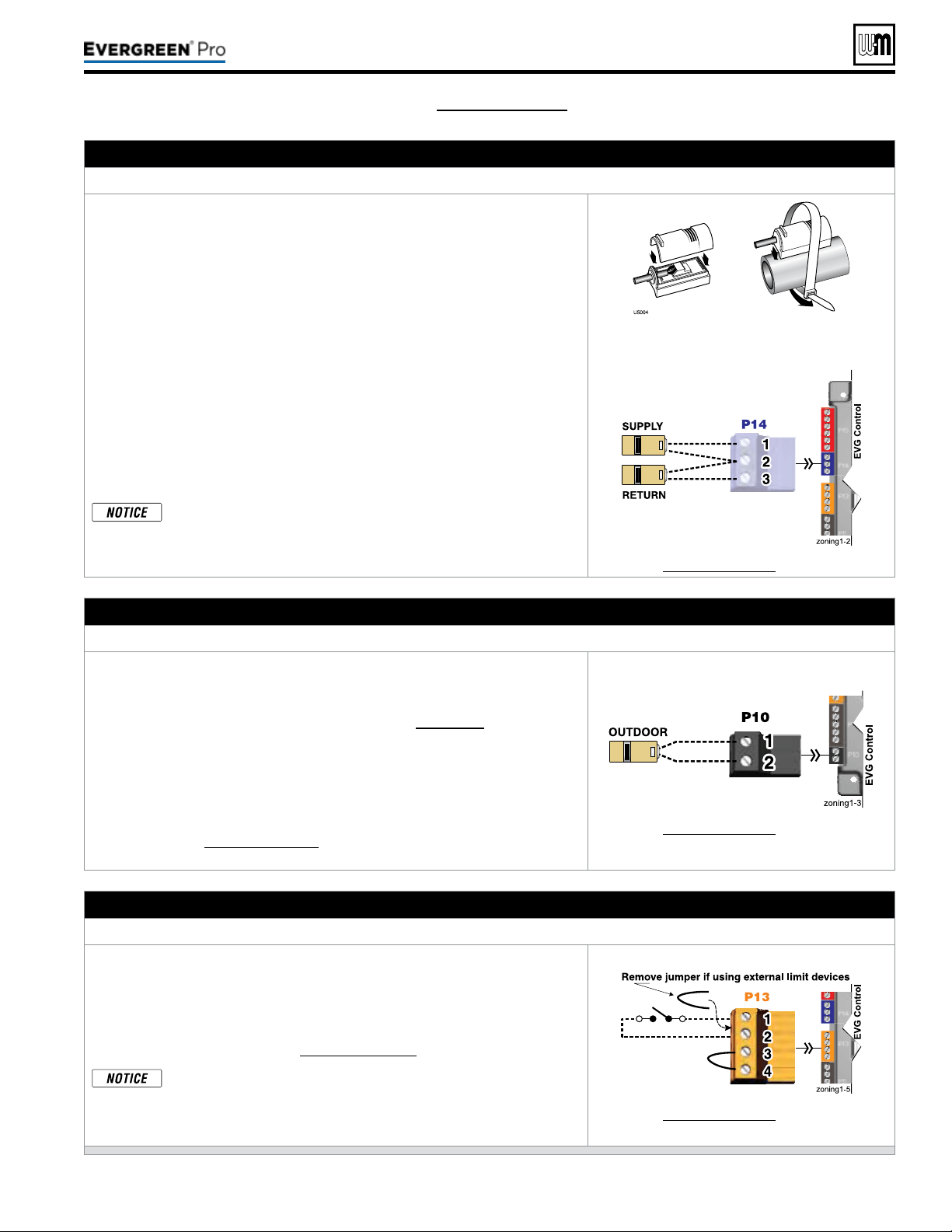
E. Systemsupplyandreturntemperaturesensors – REQUIRED
TerminalBlockP14(EVG control module, left side)
1. Two strap-on temperature sensors are shipped with the boiler. Attach one
to the system supply piping and the other to the system return piping. For
piping larger than 5inch diameter or nonmetallic piping, using immersion
sensors will provide faster response.
2. Locate the supply sensor at least six pipe diameters, but no further than 3
feet, downstream from the boiler connection to the main to ensure adequate
mixing.
3. Supply sensor – wire between P14 #1 and #2 (common).
4. Return sensor – wire between P14 #3 and #2 (common).
5. ermostat wire can be used to connect these sensors.
6. e Control compares the system return temperature with the system supply
temperature. Should the return temperature ever exceed the supply tempera-
ture, the Control knows there is likely a sensor failure and will report this
problem on the display.
All heating systems shown in this manual require the System Sup-
ply and Return sensors to be installed for proper control function.
System will not properly provide heat if sensors are not installed
according to these instructions.
Strap to supply & return piping
See Figure65,page59 for details.
F. Outdoor temperature sensor – REQUIRED unless exempted
TerminalBlockP10(EVG control module, left side)
1. e control provides programmable options if using an outdoor tempera-
ture sensor. is sensor is supplied with the boiler.
2. Theoutdoorsensormustbeinstalledunlessspecicallyex-
emptedintheEnergyActstatementonpage129.
3. Mount the outdoor sensor on an exterior wall, shielded from direct sunlight
or ow of heat or cooling from other sources.
4. e wire outlet on the sensor must be oriented DOWN to prevent water
entry.
5. Connect the sensor leads to the terminal shown at right and in the wiring
diagrams (see Figure65,page59). ermostat wire can be used to connect
the sensor.
See Figure65,page59 for details.
G. External limits – OPTIONAL
TocauseM AN UALreset:TerminalBlockP13#1(EVG control module, left side)
EVGcontrolwillrequiremanualresetaftercircuitisinterrupted
.
1. Remove factory-installed jumper and connect isolated contacts of external
limits across P13 pins1 and2 to cause the control to enter manual reset
lockout if the limit circuit opens. e limit must close and the control must
be manually reset using the procedure given in this manual. See drawing
at right and wiring diagram (Figure65,page59).
e control will lockout when a limit in its manual reset circuit
opens (P13 pins1 &2). e control activates its alarm terminals
and shuts the boiler down. An operator (user or technician) must
manually reset the control to restart the boiler.
See Figure65,page59 for details.
Loading ...
Loading ...
Loading ...