Loading ...
Loading ...
Loading ...
ELECTRICAL CONNECTIONS
WARNING: Make sure unit is off and disconnected from
power source before inspecting any wiring.
The motor is installed and wiring connected as illustrated in
the wiring schematic (see Figure 11).
The motor is assembled with an approved three conductor cord
to be used on 120 volts as indicated. The power supply to the
motor is controlled by a single pole locking rocker switch.
The power lines are inserted directly onto the switch. The
green ground line must remain securely fastened to the frame
to properly protect against electrical shock.
• Remove the key to prevent unauthorized use.
Refer to Figures 12- 80
DESCRIPTION
Craftsman 37" 5-speed wood lathe provides capability to turn
wooden workpieces up to 37" long and 4" diameter. This lathe
can also turn bowls up to 12" diameter and 4" thick. The fan
cooled motor rotates at 1720 RPM and the spindle speeds
range from 575 to 3580 RPM. Tension adjusting system makes
belt changes or speed changes quick and easy. Extended spin-
dle allows convenient outboard turning.
SPECIFICATIONS
Turning length (max.) ............................ 37"
Bowl diameter (max.) ............................ 12"
Overall length ................................. 54"
Overall height ................................ 121/4''
Width ...................................... 153/4''
Spindle speed ...................... 575 to 3580 RPM
Switch ...................... 120V, SP, Locking rocker
Motor ........................... 1720 RPM, 8 AMPS
Weight .................................... 75 Ibs
WARNING: Operation of any power tool can result in foreign
objects being thrown into the eyes, which can result in severe
eye damage. Always wear safety goggles complying with
Unites States ANSI Z87.1 (shown on package) before com-
mencing power tool operation. Safety goggles are available at
Sears retail stores or catalog.
CAUTION: Always observe the following safety precautions:
• Keep hands clear of spindle, centers, pulleys and other
moving parts of machine.
• For optimum performance, do not stall motor or reduce
speed. Do not force the tool into the work.
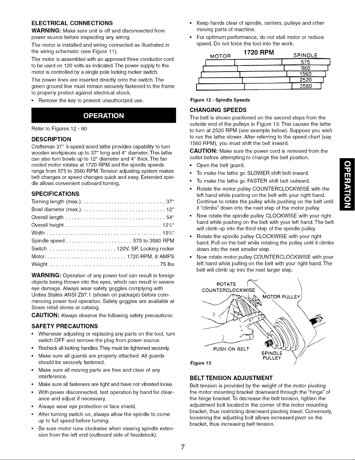
MOTOR
I 1
I I
1 I
I 1
I I
1720 RPM
SPINDLE
575 ,,11Ii, 980
I 560 I
t 2520 I
I 356o l
Figure 12 - Spindle Speeds
CHANGING SPEEDS
The belt is shown positioned on the second steps from the
outside end of the pulleys in Figure 13. This causes the lathe
to turn at 2520 RPM (see example below). Suppose you wish
to run the lathe slower. After referring to the speed chart (say
1560 RPM), you must shift the belt inward.
CAUTION: Make sure the power cord is removed from the
outlet before attempting to change the belt position.
• Open the belt guard.
• To make the lathe go SLOWER shift belt inward.
• To make the lathe go FASTER shift belt outward.
• Rotate the motor pulley COUNTERCLOCKWISE with the
left hand while pushing on the belt with your right hand.
Continue to rotate the pulley while pushing on the belt until
it "climbs" down into the next step of the motor pulley.
• Now rotate the spindle pulley CLOCKWISE with your right
hand while pushing on the belt with your left hand. The belt
will climb up into the third step of the spindle pulley.
• Rotate the spindle pulley CLOCKWISE with your right
hand. Pull on the belt while rotating the pulley until it climbs
down into the next smaller step.
• Now rotate motor pulley COUNTERCLOCKWISE with your
left hand while pulling on the belt with your right hand. The
belt will climb up into the next larger step.
ROTATE 1
COUNTERCLOCKWISE
MOTOR PULLE
SAFETY PRECAUTIONS
• Whenever adjusting or replacing any parts on the tool, turn
switch OFF and remove the plug from power source.
• Recheck all locking handles. They must be tightened securely.
• Make sure all guards are properly attached. All guards
should be securely fastened.
• Make sure all moving parts are free and clear of any
interference.
• Make sure all fasteners are tight and have not vibrated loose.
• With power disconnected, test operation by hand for clear-
ance and adjust if necessary.
• Always wear eye protection or face shield.
• After turning switch on, always allow the spindle to come
up to full speed before turning.
• Be sure motor runs clockwise when viewing spindle exten-
sion from the left end (outboard side of headstock).
Figure 13
PUSH ON BELT
SPINDLE
PULLEY
BELT TENSION ADJUSTMENT
Belt tension is provided by the weight of the motor pivoting
the motor mounting bracket downward through the "hinge" of
the hinge bracket. To decrease the belt tension, tighten the
adjustment bolt located in the corner of the motor mounting
bracket, thus restricting downward pivoting travel. Conversely,
loosening the adjusting bolt allows increased pivot on the
bracket, thus increasing belt tension.
7
Loading ...
Loading ...
Loading ...