Loading ...
Loading ...
Loading ...
IMPORTANT:Thebediscoatedwithaprotectant.Toensure
properfitandoperation,removecoating.Coatingiseasily
removedwithmildsolvents,suchasmineralspirits,andasoft
cloth.Avoidgettingcleaningsolutiononpaintoranyofthe
rubberorplasticparts.Solventsmaydeterioratethesefinish-
es.Usesoapandwateronpaint,plasticorrubbercompo-
nents.Wipeallpartsthoroughlywithacleandrycloth.Apply
pastewaxtothebed.
RefertoFigures2- 8and80.
CAUTION:Donotattemptassemblyifpartsaremissing.
Usethismanualtoorderreplacementparts.
• Removeallcomponentsfromtheshippingcartonandverify
againstthepartslistonpage3.Cleaneachcomponentand
removeshippingpreservatives(coatings)asrequired.
• Afterselectinganappropriatebench,table,orlathestand,
settheheadstock(Figure80,No.26)andattachmentson
theleftside.Installthebed(structuraltube)(Figure80,No.
35)byinsertingtheleftkeyplate(Figure80,No.36)intothe
keyslot.Securethebedusingset-screw(Figure80,No.52).
• Slidethetoolrestsupport(Figure80,No.38)ontothebed
andmoveittothemidpoint.Slidethetailstock(Figure80,No.
50)ontotheendofthebed.Slidetheassemblytowardsthe
headabout4"andsecurewithsetscrew(Figure80,No.48).
• Attachthefoot(Figure80,No.51)totheendofthebed
andsecurewithsetscrew(Figure80,No.52).
• VerifythatthepulleysandtheV-belthavebeenproperly
installedandthatthebeltguard(Figure80,No.8)isin
placeandoperatingproperly.
• Examinethelinecord(Figure80,No.14)tomakesure
thattheplugisingoodconditionandthattheinsulation
hasnotbeendamagedduringtransit.
12mmWrench Screwdriver(medium)
@ PhillipsScrewdriver
14mmWrench
----'4
Framing or Combination Square
Figure 2 - Tools Needed for Assembly and Installation
MOUNTING LATHE TO BENCH
• Drill two 3/,, holes through the top of the bench as shown in
the following illustration:
Holes for Lathe --- I
Headstock i 619/64,, I
-4 L Frontof ench
Figure 3 - Location of Mounting Holes
• Be careful not to drill into metal legs or rails under the
bench top.
• Position the headstock assembly over the holes and feed
the two 9/19x 2" long carriage bolts (not supplied) down
through the holes in the headstock and the 3/8"holes in the
bench. Secure from underneath with flat washers, lock-
washers, and hex nuts (not supplied).
• Verify that the foot (Figure 80, No. 51) is resting flat on the
bench top. Mark the mounting hole locations using the
holes in the foot as a guide. Move the lathe and drill two
more 3/j, holes through the bench top. Place the lathe back
in position and feed four 9/16x 2" carriage bolts through the
holes in the head and foot. Secure from underneath with
flat washers, Iockwashers, and hex nuts as before.
STABILITY OF WOOD LATHE
If there is any tendency for the lathe to tip over or move dur-
ing certain cutting operations, such as cutting extremely
heavy pieces or long, out-of-round objects, the lathe should
be bolted down.
LOCATION OF WOOD LATHE
The lathe should be positioned so that neither the operator
nor a casual observer is forced to stand in line with the spin-
ning chuck or workpiece.
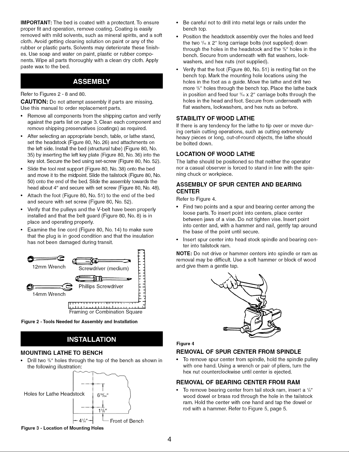
ASSEMBLY OF SPUR CENTER AND BEARING
CENTER
Refer to Figure 4.
• Find two points and a spur and bearing center among the
loose parts. To insert point into centers, place center
between jaws of a vise. Do not tighten vise. Insert point
into center and, with a hammer and nail, gently tap around
the base of the point until secure.
• Insert spur center into head stock spindle and bearing cen-
ter into tailstock ram.
NOTE: Do not drive or hammer centers into spindle or ram as
removal may be difficult. Use a soft hammer or block of wood
and give them a gentle tap.
Figure 4
REMOVAL OF SPUR CENTER FROM SPINDLE
• To remove spur center from spindle, hold the spindle pulley
with one hand. Using a wrench or pair of pliers, turn the
hex nut counterclockwise until center is ejected.
REMOVAL OF BEARING CENTER FROM RAM
• To remove bearing center from tail stock ram, insert a 1/411
wood dowel or brass rod through the hole in the tailstock
ram. Hold the center with one hand and tap the dowel or
rod with a hammer. Refer to Figure 5, page 5.
4
Loading ...
Loading ...
Loading ...