Loading ...
Loading ...
Loading ...
POWER SOURCE
WARNING: Do not connect wood lathe to the power source
until all assembly steps have been completed.
The motor is designed for operation on the voltage and frequency
specified. Normal loads will be handled safely on voltages not
more than 10% above or below specified voltage. Running the
unit on voltages which are not within range may cause overheat-
ing and motor burn-out. Heavy loads require that voltage at motor
terminals be no less than the voltage specified on nameplate.
• Power supply to the motor is controlled by a single pole locking
rocker switch. Remove the key to prevent unauthorized use.
GROUNDING INSTRUCTIONS
WARNING: Improper connection of equipment grounding con-
ductor can result in the risk of electrical shock. Equipment should
be grounded while in use to protect operator from electrical shock.
• Check with a qualified electrician if grounding instructions
are not understood or if in doubt as to whether the tool is
properly grounded.
• This tool is equipped with an approved 3-conductor cord
rated at 150V and a 3-prong grounding type plug (see Figure
9) for your protection against shock hazards.
• Grounding plug should be plugged directly into a properly
installed and grounded 3-prong grounding-type receptacle,
as shown (Figure 9).
Grounded Outlet
Properly __
Grounding Prong
3-Prong Plug
Figure 9 - 3-Prong Receptacle
• Do not remove or alter grounding prong in any manner. In
the event of a malfunction or breakdown, grounding pro-
vides a path of least resistance for electrical shock.
WARNING: Do not permit fingers to touch the terminals of
plug when installing or removing from outlet.
• Plug must be plugged into matching outlet that is properly
installed and grounded in accordance with all local codes and
ordinances. Do not modify plug provided. If it will not fit in
outlet, have proper outlet installed by a qualified electrician.
• Inspect tool cords periodically and if damaged, have them-
repaired by an authorized service facility.
• Green (or green and yellow) conductor in cord is the
grounding wire. If repair or replacement of the electric cord
or plug is necessary, do not connect the green (or green
and yellow) wire to a live terminal.
• Where a 2-prong wall receptacle is encountered, it must be
replaced with a properly grounded 3-prong receptacle
installed in accordance with National Electric Code and
local codes and ordinances.
WARNING: This work should be performed by a qualified
electrician.
A temporary 3-prong to 2-prong grounding adapter (see Figure
10) is available for connecting plugs to a two pole outlet if it is
properly grounded.
• Do not use a 3-prong to 2-prong grounding adapter unless
permitted by local and national codes and ordinances.
• (A 3-prong to 2-prong grounding adapter is not permitted
in Canada.) Where permitted, the rigid green tab or terminal
on the side of the adapter must be securely connected to a
permanent electrical ground such as a properly grounded
water pipe, a properly grounded outlet box or a properly
grounded wire system.
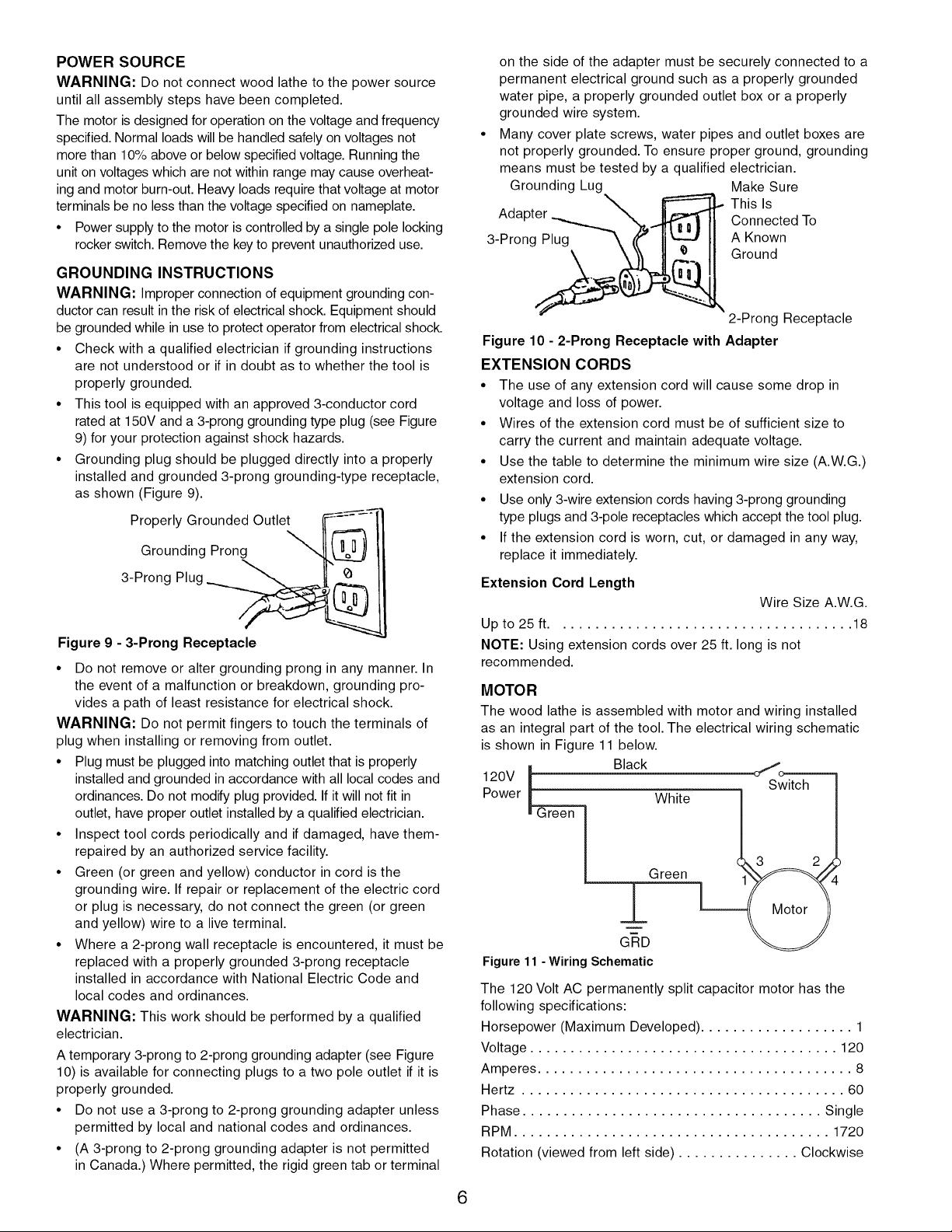
• Many cover plate screws, water pipes and outlet boxes are
not properly grounded. To ensure proper ground, grounding
means must be tested by a qualified electrician.
Grounding Lug Make Sure
Ada This Is
Connected To
3-Prong Plug A Known
Ground
2-Prong Receptacle
Figure 10 - 2-Prong Receptacle with Adapter
EXTENSION CORDS
• The use of any extension cord will cause some drop in
voltage and loss of power.
• Wires of the extension cord must be of sufficient size to
carry the current and maintain adequate voltage.
• Use the table to determine the minimum wire size (A.W.G.)
extension cord.
• Use only 3-wire extension cords having 3-prong grounding
type plugs and 3-pole receptacles which accept the tool plug.
• If the extension cord is worn, cut, or damaged in any way,
replace it immediately.
Extension Cord Length
Wire Size A.W.G.
Up to 25 ft..................................... 18
NOTE: Using extension cords over 25 ft. long is not
recommended.
MOTOR
The wood lathe is assembled with motor and wiring installed
as an integral part of the tool. The electrical wiring schematic
is shown in Figure 11 below.
120V } Black
Power _ White
Green
±
GND
Figure 11 - Wiring Schematic
The 120 Volt AC permanently split capacitor motor has the
following specifications:
Horsepower (Maximum Developed) ................... 1
Voltage ...................................... 120
Amperes ....................................... 8
Hertz ........................................ 60
Phase ..................................... Single
RPM ....................................... 1720
Rotation (viewed from left side) ............... Clockwise
6
Loading ...
Loading ...
Loading ...