
Loading ...
Loading ...
Loading ...
113
SPECIFICATIONS
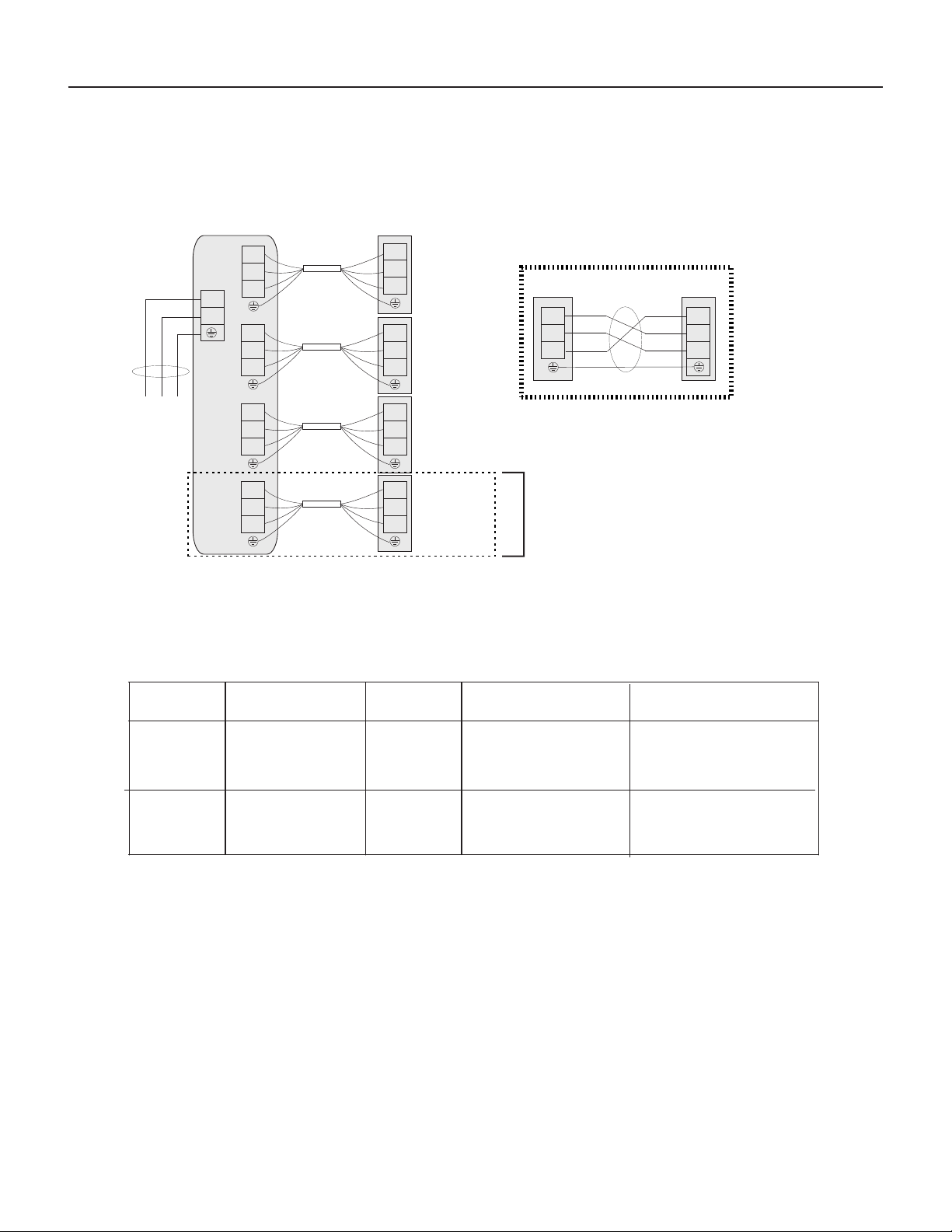
Electrical Requirements 24k and 36k Outdoor Units
Electrical wiring diagram
Recommended Wire
Size
Electrical Data
Capacity
Model
Power Supply
Max
. Running Current (A ): REFER TO NAMEPLATE
Transmitting ecruoS rewoP
eziS elbaCeziS elbaCCurrent (A)
Nominal
24K
208/230V ~, 60Hz
30
36K 208/230V ~, 60Hz 40
Outdoor unit
Indoor unit B
Indoor unit A
-Use the appropriate size breaker for the specified amperage.
-Do not operate the system until all the check points have been cleared.
-Check to ensure that the insulation resistance is greater than 2M Ohm, by measuring the
resistance between ground and the terminal of the electrical parts. If not, do not operate the
system until the electrical leakag e is found and repaired.
-Check to ensure that the stop valves of the outdoor unit are fully opened before starting the
system.
Indoor unit C
Terminal
Terminal B
Terminal A
Terminal C
Terminal
Terminal
Terminal
Power supply
4(SI)
4(SI)
4(SI)
4(SI)
4(SI)
4(SI)
1(L)
1(L)
1(L)
1(L)
1(L)
1(L)
2(N)
2(N)
2(N)
2(N)
2(N)
2(N)
Power connecting cord
Power connecting cord
Power connecting cord
L2
L1
Outdoor unit
Indoor unit
4(SI)
3(SI)
1(L)
2(L)
2(N)
1(N)
Power connecting cord
Important: Wiring for wall mounted units
Indoor unit D
Terminal D
Terminal
4(SI)
4(SI)
1(L)
1(L)
2(N)
2(N)
Power connecting cord
36k only
3x10AWG
(2x Conductors, 1x Ground)
600V, Solid or THHN
4x14AWG
600V THHN ONLY
3x8AWG
(2x Conductors, 1x Ground)
600V, Solid or THHN
4x14AWG
600V THHN ONLY
Loading ...
Loading ...
Loading ...