Loading ...
Loading ...
Loading ...
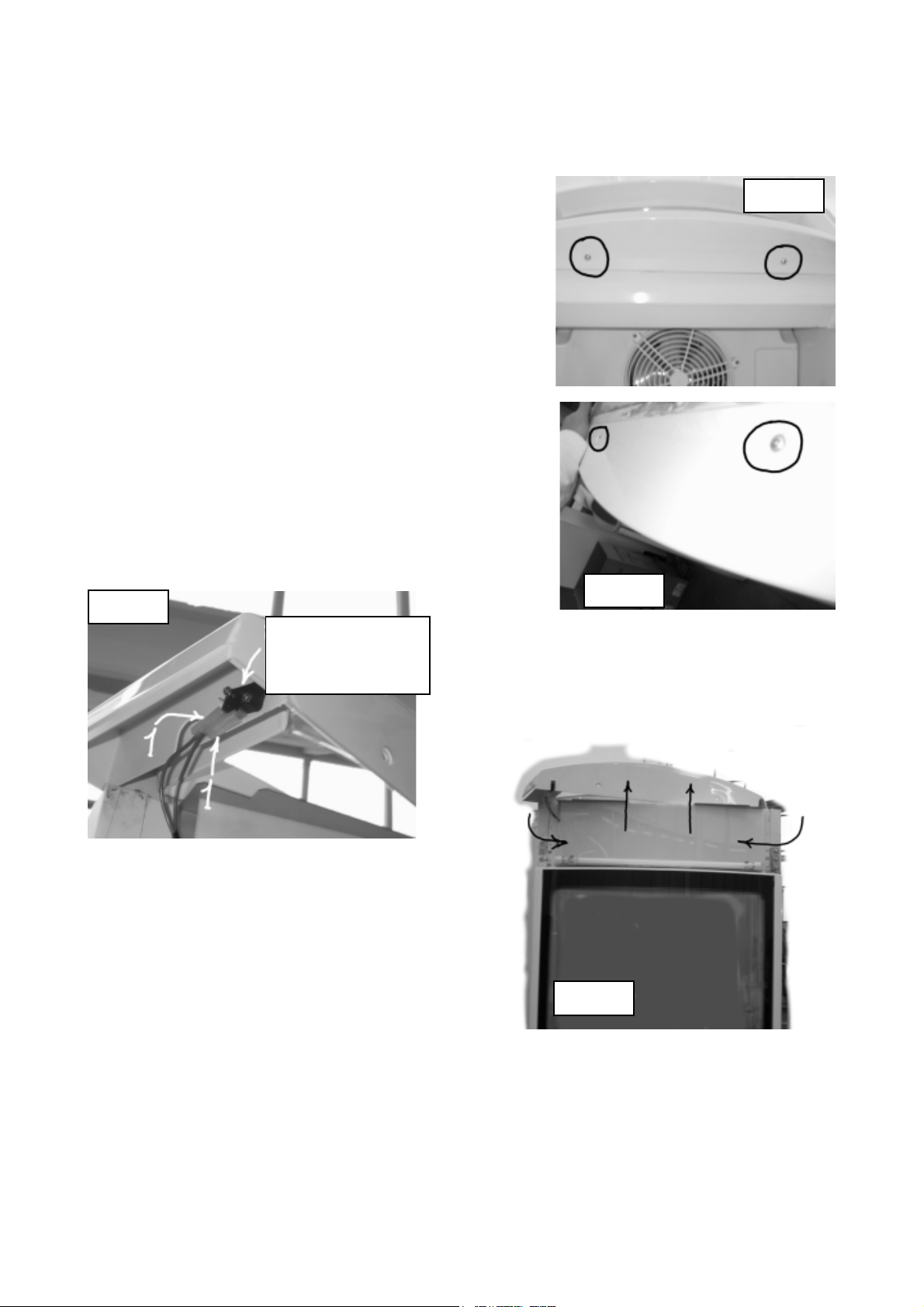
2.6 ELECTRICAL COMPONENTS IN THE DISPLAY COMPARTMENT
To access the display compartment loosen the 4 fixing
screws circled in fig. 19 and 20 and remove the display
plastic frame (9) and the display panel (42), indicated in
fig. 22. In the display compartment you can see:
1. Door switch (IP) (36): it stops the evaporator motor
fan every time the door is opened (fig. 21) and is
located in the display plastic frame (9).
2. Display lamp (L1) (33): T5 type (o.d. 16 mm) and
13W.
3. Display lamp starter (S1) (73).
To access the display lamp starter remove the
transparent panel (42), indicated by arrows in fig. 22.
FIG. 19
FIG. 20
FIG. 21
FIG. 22
- 18 -
Door switch
Loading ...
Loading ...
Loading ...