Loading ...
Loading ...
Loading ...
2.5 MECHANICAL AND ELECTRICAL COMPONENT PARTS AT THE
BACK OF THE CABINET
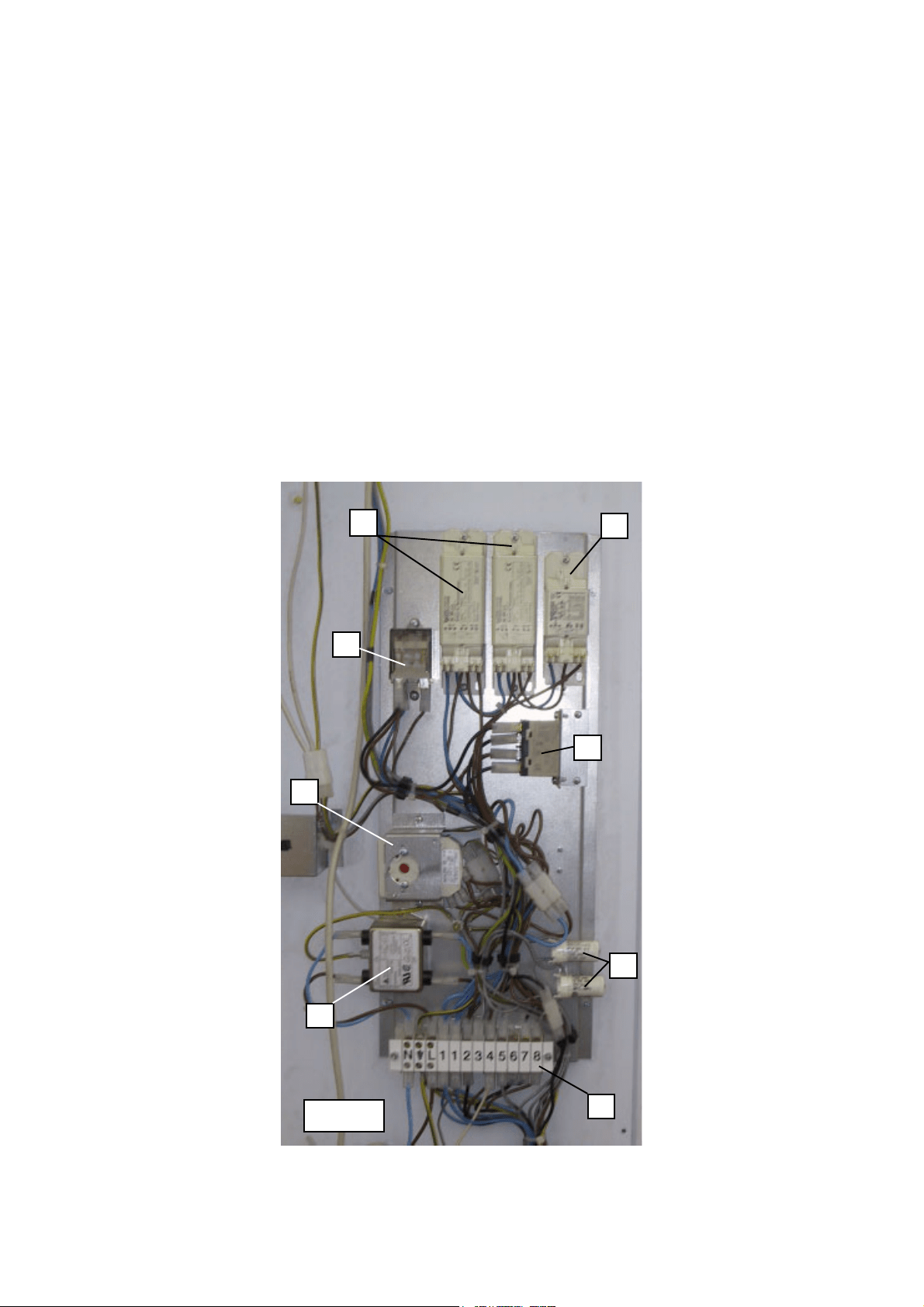
Remove the rear metal cover sheet, by removing the 9 screws shown in fig. 5, 6, 7 and 8:
on the right, above the compressor compartment, there is a metal support to which the
electrical components are secured. These components are shown in fig. 18b:
1. Defrosting relay (RS) (61): double switching contacts to activate the defrosting phase.
2. Compressor relay (RC) (62): single contact, normally open, to operate the compressor.
3. Inner lamps starters (S2) (73): to strike the electric discharge in the gas lamp.
4. Display lamp ballast (AT1) (59): to supply the display lamp.
5. Inner lamps ballasts (AT2) (60): to supply the tank lamps.
6. Defrosting timer (TS) (81): controls the defrosting cycle.
7. Connecting terminal board.
8. EMC filter (FRF) (22).
- 16 -
FIG.18b
3
1
2
4
5
6
7
8
Loading ...
Loading ...
Loading ...