Loading ...
Loading ...
Loading ...
2 Hardware Installation DES-1210/ME Series Metro Ethernet Managed Switch User Manual
9
9
Figure 2.5 – Plugging the switch into an outlet
Power Failure
As a precaution, the switch should be unplugged in case of power failure. When power is resumed, plug the
switch back in.
Grounding the Switch
This section describes how to connect the DES-1210/ME Series Switch to ground. You must complete this
procedure before powering your switch.
Required Tools and Equipment
Ground screws (included in the accessory kit): One M4 x 6 mm (metric) pan-head screw.
Ground cable (not included in the accessory kit): The grounding cable should be sized according to
local and national installation requirements. Depending on the power supply and system, a 12 to 6
AWG copper conductor is required for U.S installation. Commercially available 6 AWG wire is
recommended. The length of the cable depends on the proximity of the switch to proper grounding
facilities.
A screwdriver (not included in the accessory kit)
The following steps let you connect the switch to a protective ground:
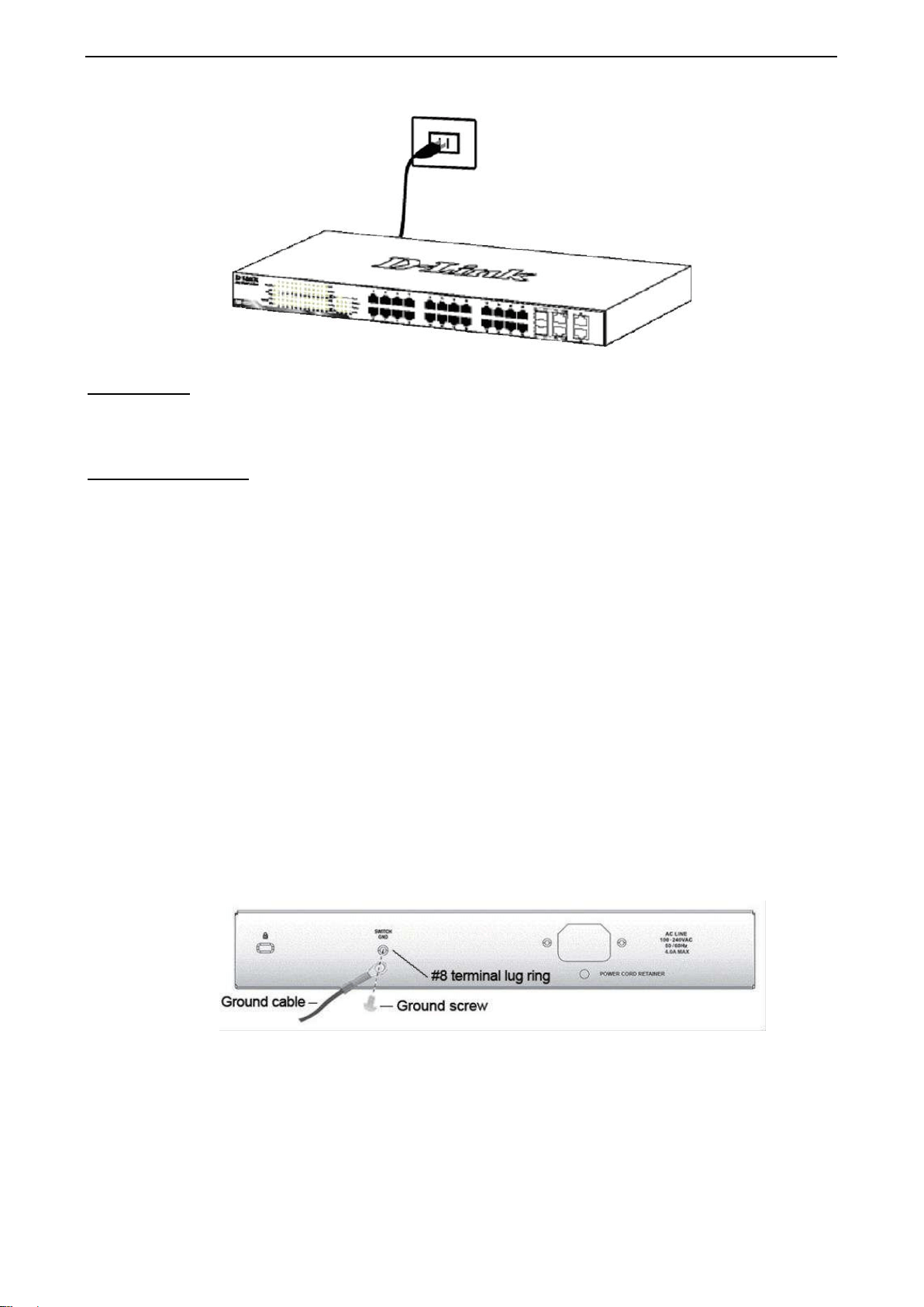
Step 1: Verify if the system power is off.
Step 2: Use the ground cable to place the #8 terminal lug ring on top of the ground-screw opening, as
seen in the figure below.
Step 3: Insert the ground screw into the ground-screw opening.
Step 4: Using a screwdriver, tighten the ground screw to secure the ground cable to the switch.
Step 5: Attach the terminal lug ring at the other end of the grounding cable to an appropriate grounding
stud or bolt on rack where the switch is installed.
Step 6: Verify if the connections at the ground connector on the switch and the rack are securely
attached.
Figure 2.6 – Connect a Grounding Cable
Loading ...
Loading ...
Loading ...