Loading ...
Loading ...
Loading ...
1 Product Introduction DES-1210/ME Series Metro Ethernet Managed Switch User Manual
4
Amber
Solid Light
When there is a secure 100Mbps
Ethernet connection (or link) at any
of the ports.
Blinking
When there is reception or
transmission (i.e. Activity—Act) of
data occurring at a 100Mbps
Ethernet connected port.
Off
Light off
No link.
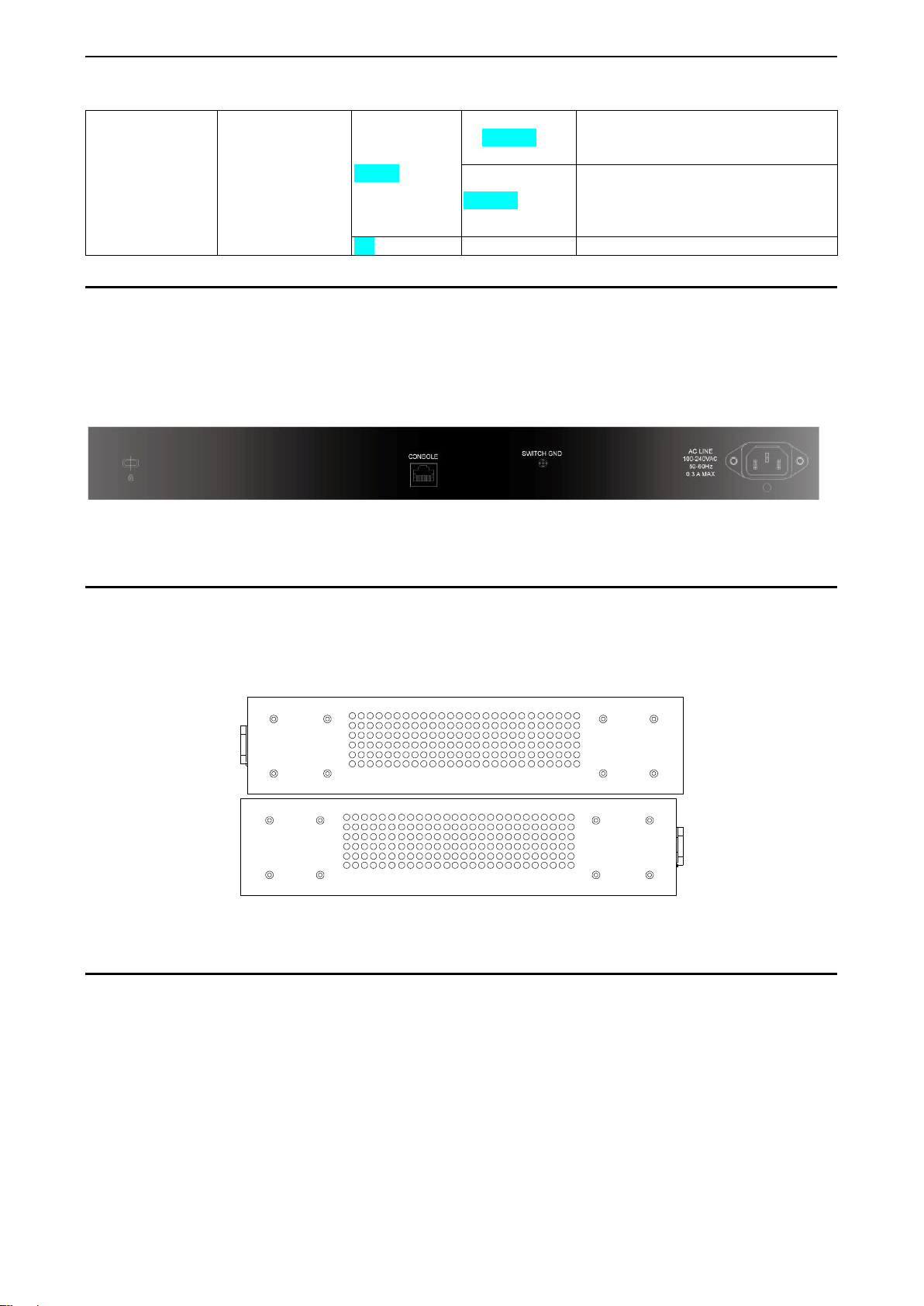
Rear Panel Description
The rear panel of the Switch contains and AC power connector, console port and Switch Grounding. The AC
power connector is a standard three-pronged connector that supports the power cord. Plug-in the female
connector of the provided power cord into this socket, and the male side of the cord into a power outlet. The
Switch automatically adjusts its power setting to any supply voltage in the range from 100 to 240 VAC at 50
to 60 Hz. Connect the Kensington-compatible security lock, at the rear of the switch, to a secure immovable
device. Insert the lock into the notch and turn the key to secure the lock.
Figure 1.3 –Rear panel view of the DES-1210-52/ME
Side Panel Description
The left- and right-hand panels of the Switch have heat vents to dissipate heat. Do not block these openings,
and leave at least 6 inches of space at the rear and sides of the Switch for proper ventilation. Be reminded
that without proper heat dissipation and air circulation, system components might overheat, which could lead
to system failure.
Figure 1.4 - Side panels of the DES-1210-52/ME
Gigabit Combo Ports
The DES-1210-52/ME features four Gigabit Ethernet Combo ports. These ports are 1000BASE-T copper
ports (optional) and Small Form Factor Portable (SFP) ports (optional). See the diagram below to view the
two SFP port modules being plugged into the Switch. Please note that although these two front panel
modules can be used simultaneously, the ports must be different. The SFP port will always have the highest
priority.
Loading ...
Loading ...
Loading ...