Loading ...
Loading ...
Loading ...
CVP-709/CVP-705 Owner’s Manual
106
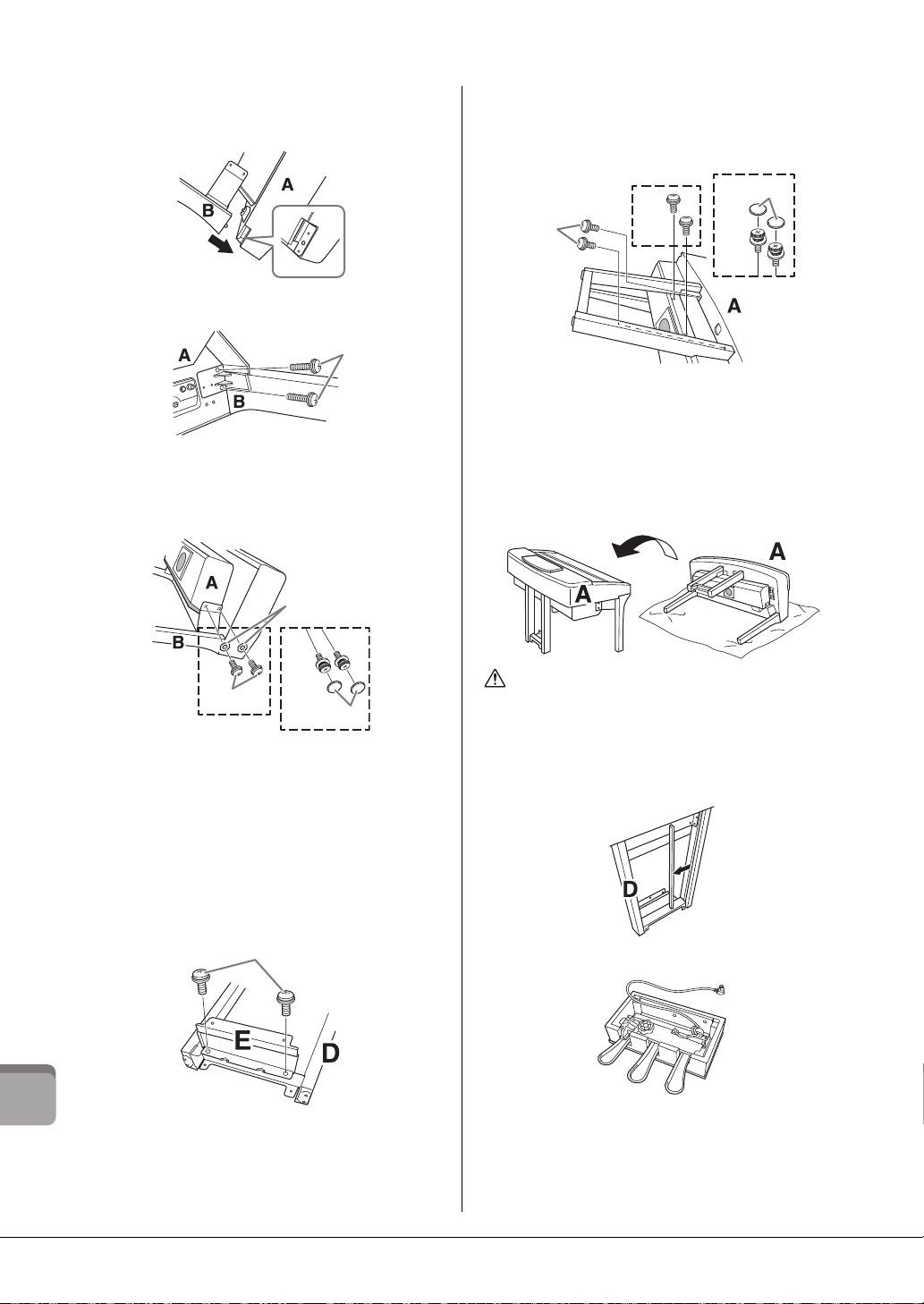
CVP-709 Assembly
2 Attach units B and C to unit A.
1 Align units B and A so that the protrusion fits into the hole.
2 Fix unit B to the bottom surface of unit A using two screws
H.
Attach the parts, pressing unit B onto unit A so that the two
fit tightly together.
3 Fix unit B to the speaker box of unit A using two screws J.
If the screw holes do not align, loosen the other screws and
adjust the position of unit B.
4 (CVP-709PWH) Attach two caps K.
5 Fasten unit C to unit A in the same way.
3 Attach unit E to unit D.
Fix unit E to unit D using two screws L.
4 Attach unit D to unit A.
1 Fix unit D to the bottom surface of unit A using two screws
L.
2 Fix unit D to the speaker box of unit A using two screws J.
If the screw holes do not align, loosen the other screws and
adjust the position of unit D.
3 (CVP-709PWH) Attach two caps K.
5 Raise unit A into the upright position.
CAUTION
• Be careful not to pinch your fingers.
• When you raise the unit, do not hold the key cover.
6 Install unit F.
1 Remove the cover from unit D.
2 Untie and straighten out the bundled cord.
H
CVP-709B
CVP-709PE
CVP-709PWH
3
J
3
J
4
K
Q
L
1
2
L
J
DD
2
J
CVP-709B
CVP-709PE
CVP-709PWH
3
K
F
F
Loading ...
Loading ...
Loading ...