Loading ...
Loading ...
Loading ...
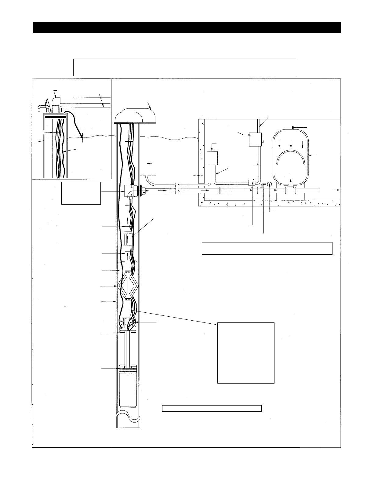
INSTALLATION
Figure 7 - Pump Installation
PICTORIAL OF 3-WIRE SYSTEM WITH AND WITHOUT A PITLESS ADAPTER
(SEE PAGE 10 FIGURE 9 IN THIS MANUAL FOR WIRING DIAGRAMS)
DISCHARGE PIPING REQUIREMENTS
• 5 gpm pumps 1" pipe
• 7 gpm pumps 1" pipe
• 10 gpm pumps 1" pipe is OK to 300 ft depth to water
• 10 gpm pumps 1¼" pipe if the depth to water exceeds 300 ft
CABLE
TIE
CONDUIT
FOR CABLE
IRON
ANCHOR
POST
VENTILATED
WELL CAP
SERVICE ENTRANCE
115 OR 230V
SUPPLY VOLTAGE
CONDUIT
TO SERVICE
FROST LINE
SPRING LOADED
CHECK VALVE
(RECOMMENDED
EVERY 200ft / 60 m)
CABLE TIE
OR TAPE
WELL CASING
POWER CABLES
AND GROUND
WIRE FROM
PUMP MOTOR
BUILT-IN CHECK VALVE
PUMP SUCTION
PUMP & MOTOR
DISCHARGE PIPE
(SEE NOTES BELOW)
NOTES
90º
ELBOW
POLY SAFETY
ROPE
Used to support weight of
the pump.
AIR VALVE
Pressurize tank @ 2
PSI below pressure
switch cut-in setting.
CAPTIVE AIR
PRESSURE
TANK
Offers
water storage
for fewer pump
cycles. Provides
air cushion to oper-
ate against. Tank
should be sized so
that draw down is
equal to capacity
of pump.
PITLESS ADAPTOR
INSTALLATION
For underground connection
of well pipe to horizontal pipe
providing a sanitary seal.
POLY SAFETY ROPE Used to
support weight of the pump.
TORQUE ARRESTOR
Absorbs thrust of motor start-ups.
Keeps pump centered in well. Various
types are available.
PRESSURE GAUGE Indicates systems
pressure at all times.
PUMP CONTROL
BOX Contains com-
ponents for three-wire
with ground motors.
CIRCUIT BREAKER
OR FUSED DISCONNECT
SWITCH
STANDARD PRESSURE SWITCH OR
"LOSS OF PRESSURE" SWITCH
Senses system pressure and automatically
turns pump on and off.
VENTED
WELL SEAL
Keeps debris
out of well.
TO PRESSURE PUMP TANK
If 1" semi-rigid plastic
pipe or steel pipe is
used, install 1¼" x 1"
reducer bushing
If 1" polyethylene pipe
is used, install 1" male
plastic pipe adapter,
along with 2 stainless
steel clamps
CONDUIT FOR PUMP
CABLE
Electric cable either three-wire
or two-wire with ground. Selec-
tion of proper size wire assures
required voltage to motor. (see
Table 1 page 3)
Use of Check Valves
Your pump is equipped with a built-in check located in the discharge head of the pump.
For deeper pump settings it is recommended that additional spring loaded inline check valves
be installed in the drop pipe @ 200 ft / 60 m intervals.
Check valves are used to hold pressure when the pump stops. They are also used to prevent
backspin, water hammer, and upthrust. Any of these three, or a combination of them, can
lead to immediate pump or motor failure, a shortened service life or operating problems
in the system.
PRESSURE RELIEF VALVE Protection against pressure buildup. Particularly vital where the
pump is capable of producing more pressure than the working limits of the tank.
WARNING! To prevent the possibility of dangerously high pressure, install a relief valve in
the discharge pipe between pump and flow restriction valve. Relief valve
must be capable
of passing full pump flow at 75 PSI.
8
Loading ...
Loading ...
Loading ...