Loading ...
Loading ...
Loading ...
• Install the well seal into the well casing by tightening
down cap screws on the well seal. The well seal
must be vented.
• Continue pipe connection to the tank location in the
house. Continue securing the submersible pump
cable to the pipe. Additional clamps and fittings will
be required to make the necessary connections at
the elbow and at the control center.
INSTALLING THE CONTROL CENTER
(Figure 5)
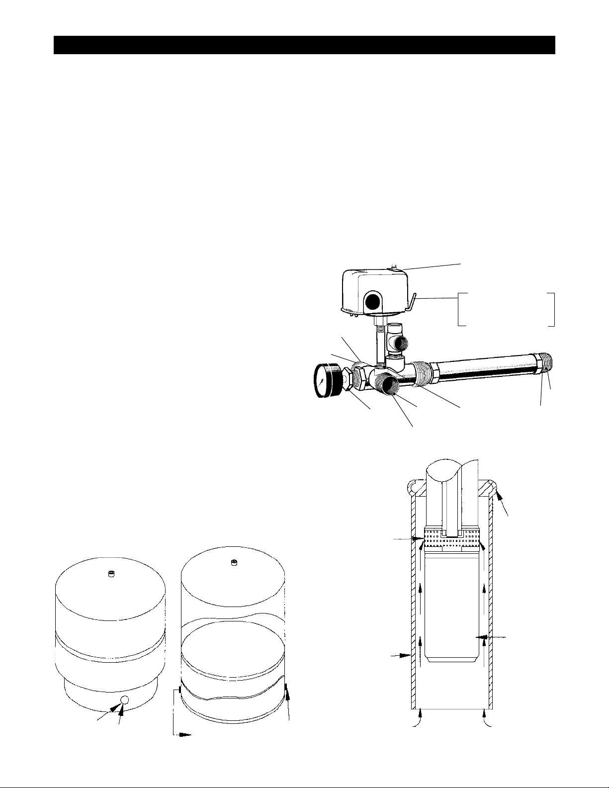
Note: PTFE tape must be used on all thread joints.
• Wrap the outside thread of the tank control center
with PTFE tape at position (A) and thread into tank
opening (see Figure 4). Control center will thread
directly into 1" opening in the side of the pre-
charged tank.
• Install the pressure gauge with a ¾" x ¼" bushing at
the opening marked position (B) on the control center.
• Install A pressure switch or “loss of pressure”
switch using ¼" x 3" nipple at the opening position
(C) in the control center.
• Connect pipe coming from well and pump
to position (E) in the control center using the
appropriate male plastic pipe adapter and clamp, if
polyethylene is used, or thread directly into control
center if ABS or steel pipe is used.
• Proceed from position (D) on the control center to
house service lines.
NOTE: The use of PTFE tape is recommended on all
threaded joints.
NOTE: It is recommended that the 1 hp and 1½ hp
models should not be installed where the pumping
level is less than 30 m (100 ft).
INSTALLATION
LAKE OR LARGE DIAMETER WELL INSTALLATION
All wiring, electrical connections, and system grounding
must comply with the National Electrical Code (NEC)
and with any local codes and ordinances. Employ a
licensed electrician.
If a pump is installed in a lake or large diameter well, a
flow inducer sleeve must be placed around the motor.
The sleeve should have an inside diameter of 4" to
6", and be composed of corrosion-resistant metal or
heavy plastic. The sleeve will ensure proper flow of
water around the motor for cooling purposes. The flow
inducer sleeve is closed off above the pump intake and
extends to the bottom of the motor or lower as shown
in Figure 6.
Figure 4 - Tank Openings
A
To Tank
Control Center
Float air
separator
To Tank
Control Center
1¼" Plug
Required
"Captive Air"
Precharged Tank
Epoxy or Glass Lined
Prechargeable Tank
Figure 5 - The Control Center
AUTO_
START_
OFF_
To Tank
Opening
A
C
E
To Pump
B
To Service
Line
D
Standard Pressure
Switch or "Loss of
Pressure Switch"
"Loss of Pressure
Switch" Illustrated with
Reset Lever
Figure 6 - Flow Inducer Sleeve
Flow Inducer
Sleeve
Water flows up the sleeve and
around the motor
Motor
Seal
Pump
Intake
7
Loading ...
Loading ...
Loading ...