Owner's Guide Fitness
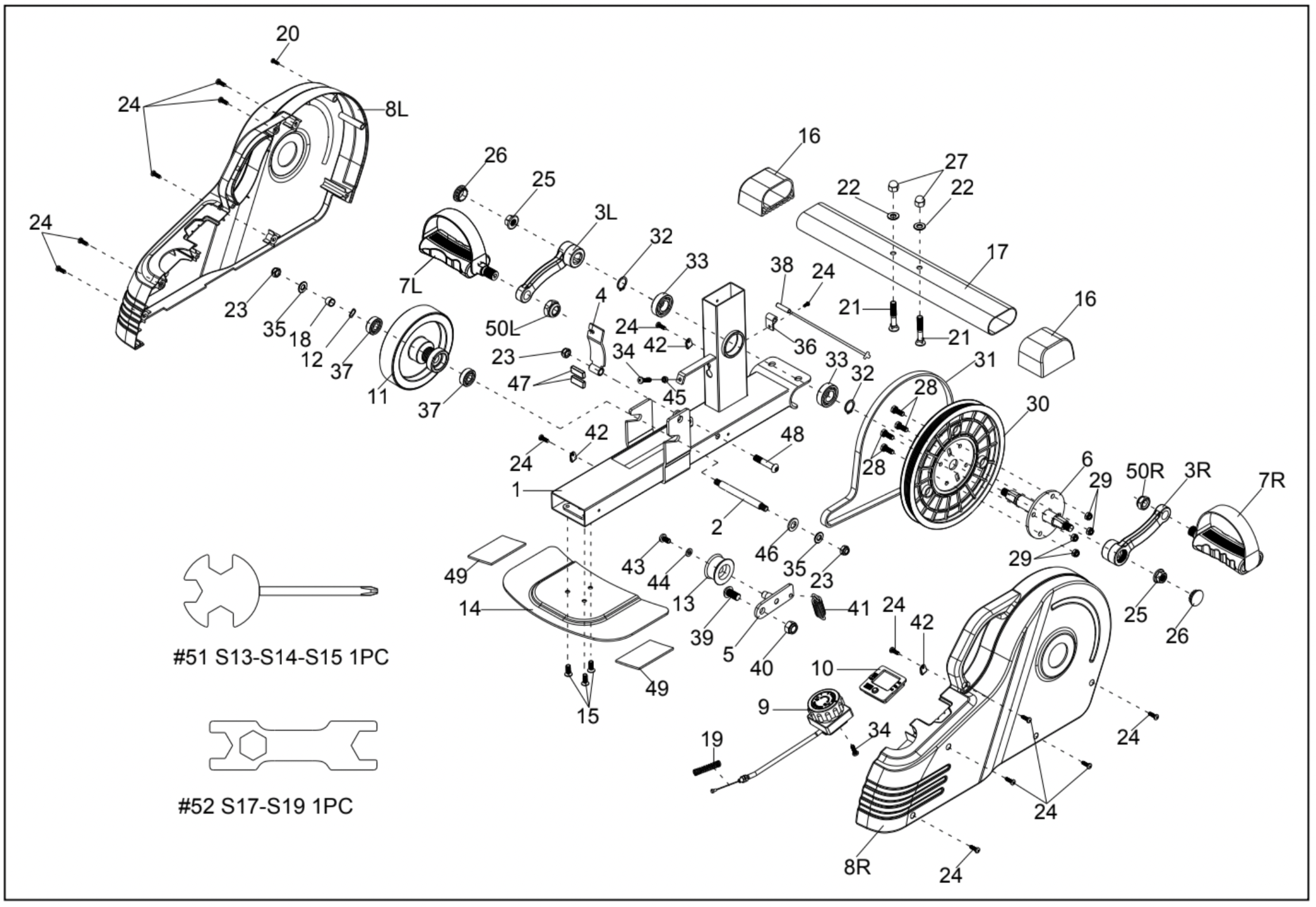
EXPLODED DIAGRAM
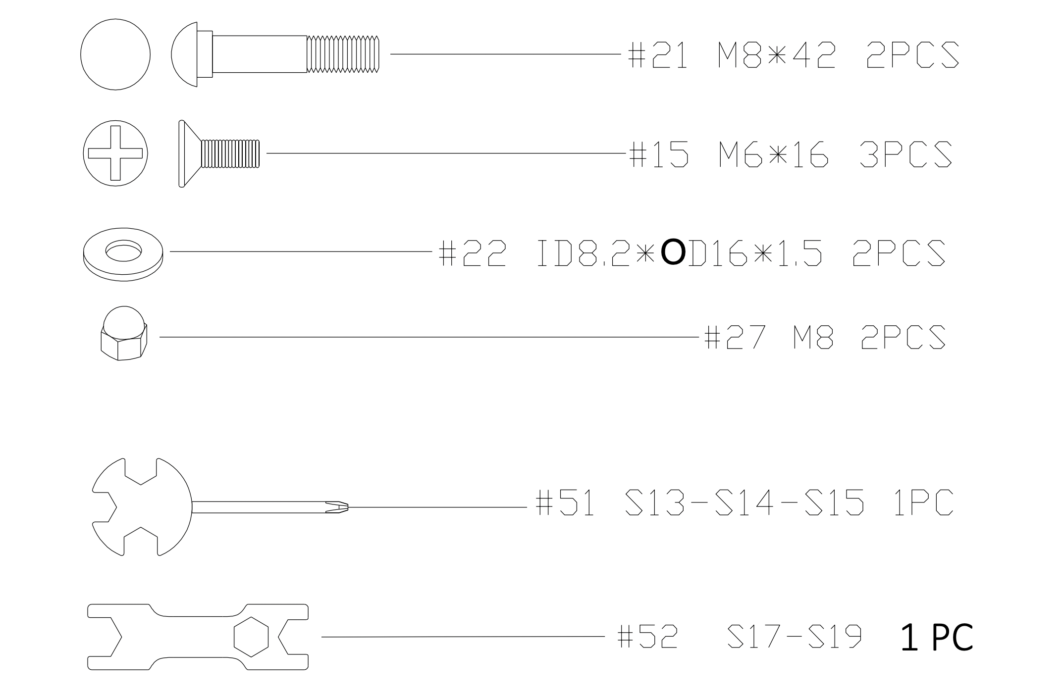
HARDWARE PACKAGE
ASSEMBLY INSTRUCTIONS
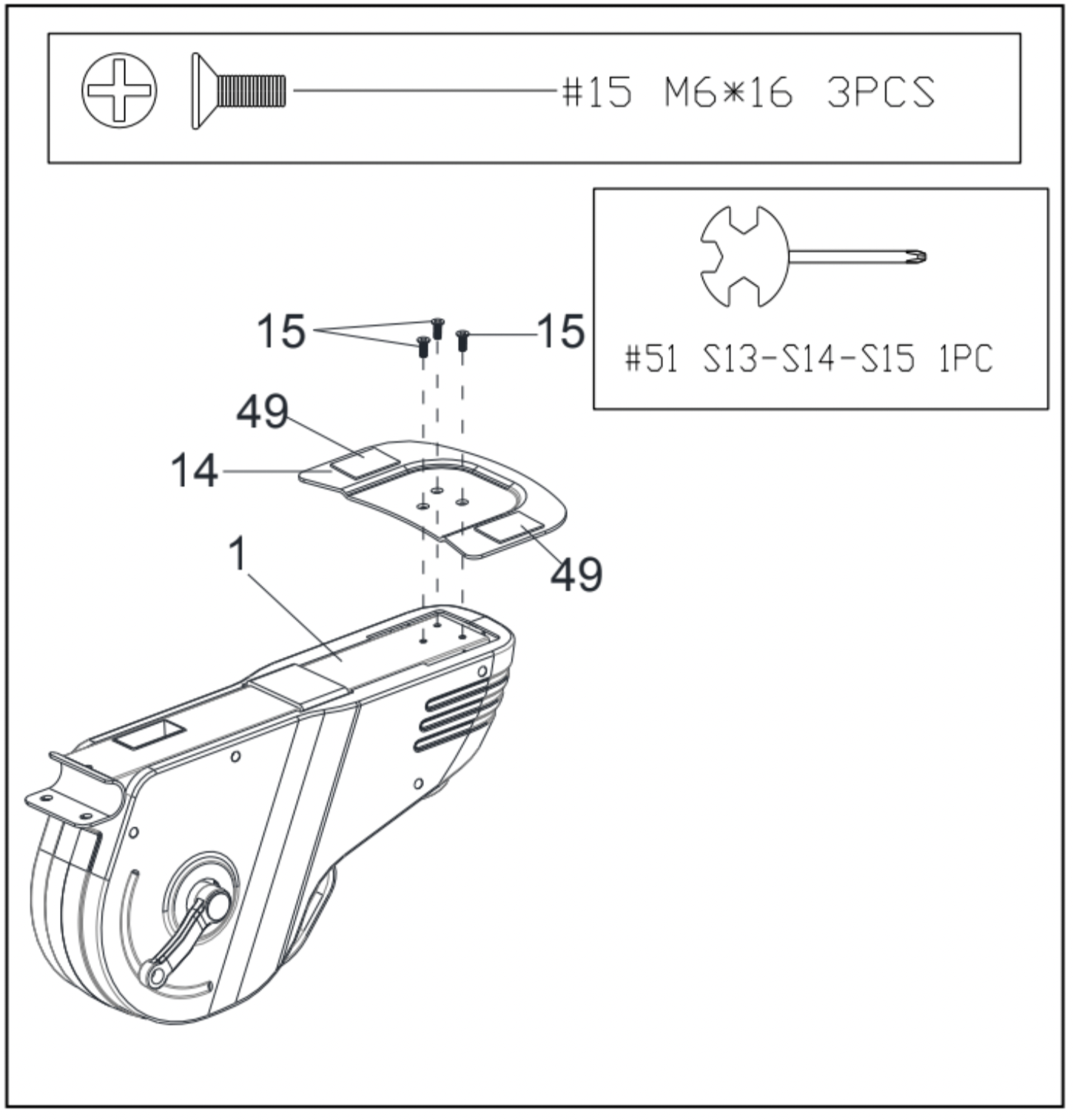
STEP 1: Attach Rear Fixed Bottom Plate (No. 14) to the Main Frame (No. 1) with 3 Bolts (No. 15). Tighten and secure with Spanner (No. 51).
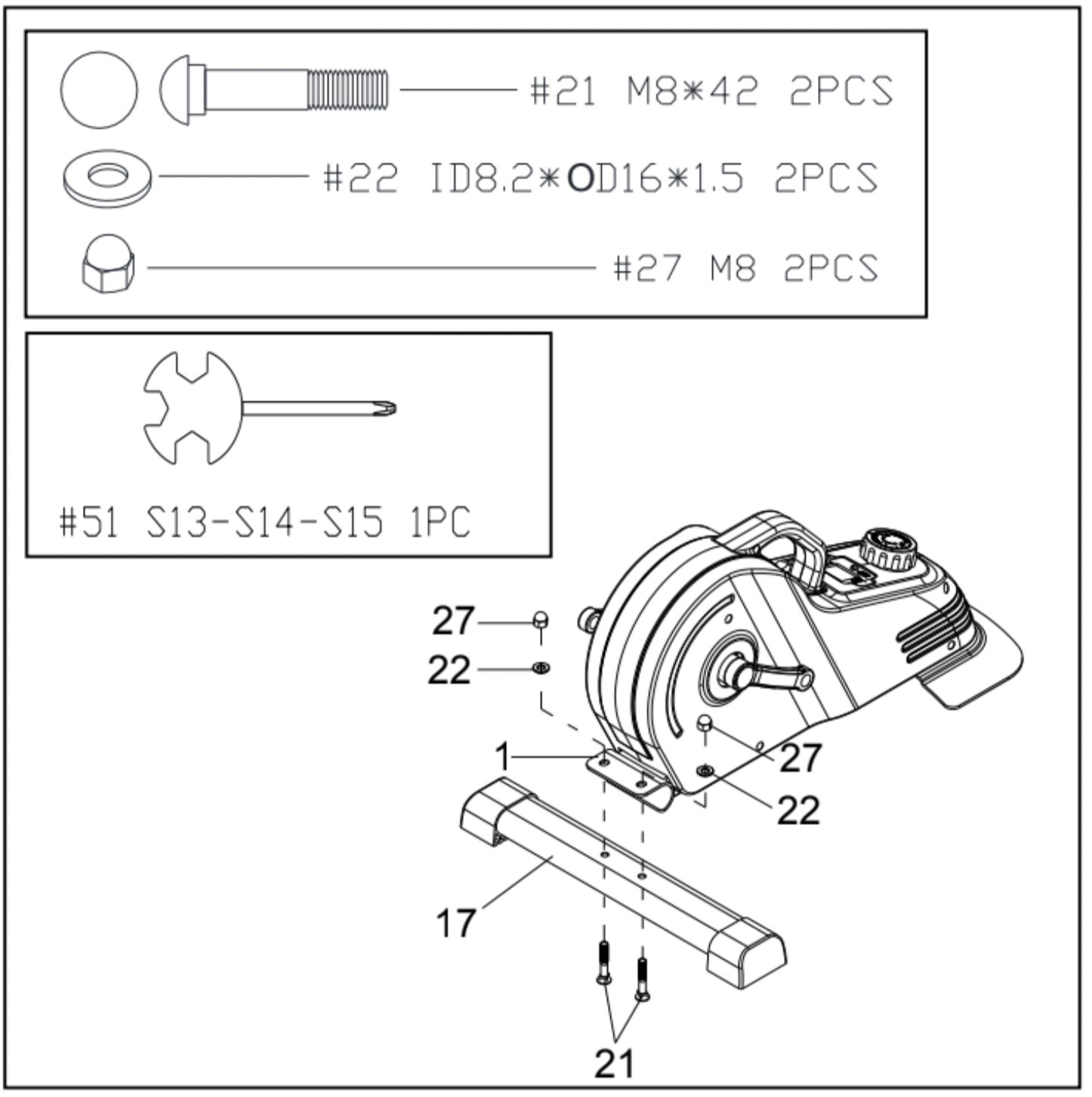
STEP 2: Attach Front Stabilizer (No. 17) to the Main Frame (No. 1) with 2 Carriage Bolts (No. 21), 2 Washers (No. 22), and 2 High Cap Nuts (No. 27). Tighten and secure with Spanner (No. 51).
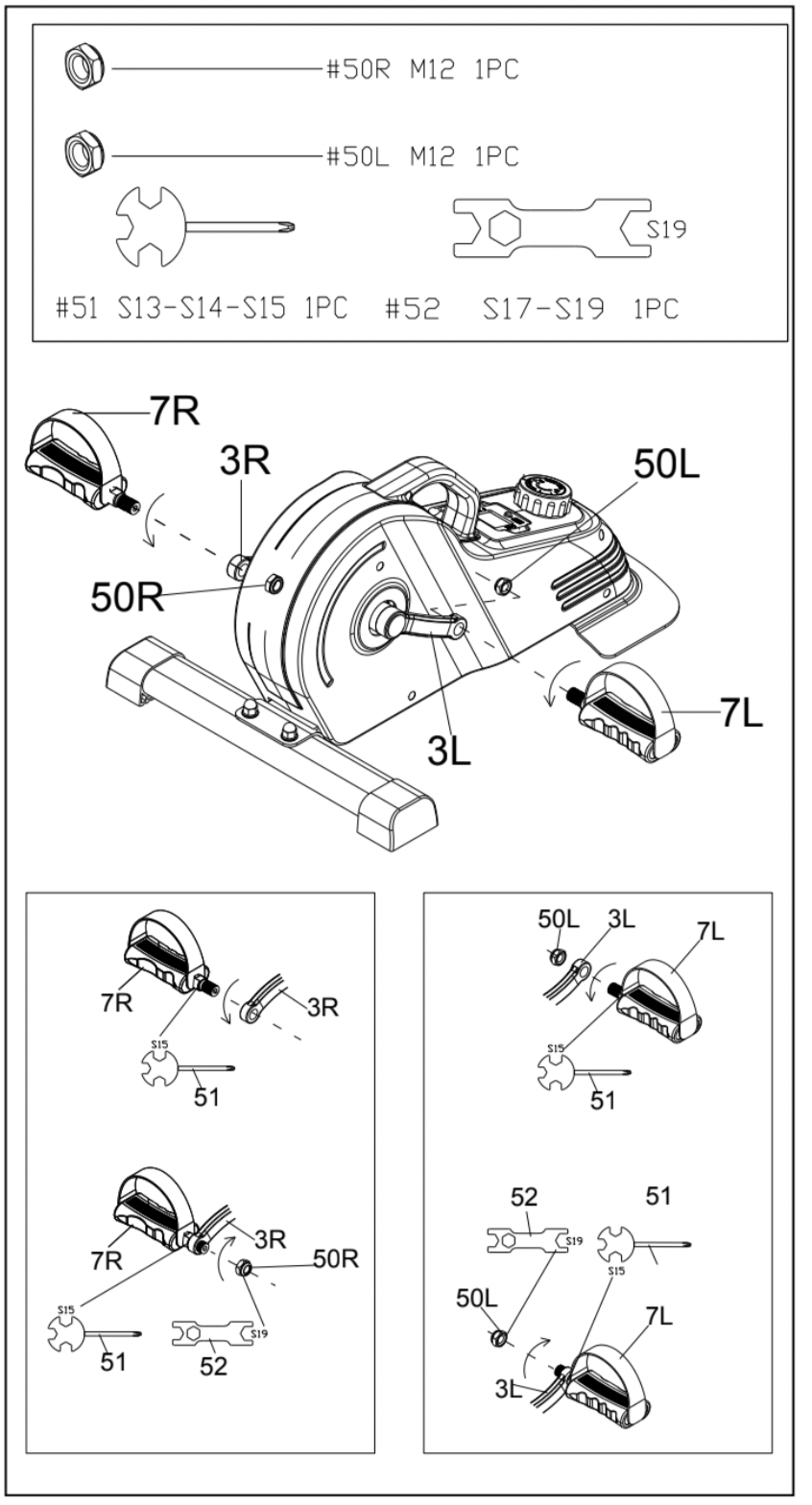
STEP 3:
NOTE: The Pedals (No. 7L & No. 7R) are marked “L” and “R” for Left and Right.
WARNING! Read instructions carefully as improper assembly may cause permanent damage to your bike.
Remove the 2 Left & Right Nylon Nuts (No. 50L & No. 50R) located on the Pedals (No. 7L & No. 7R).
Align the Left Pedal (No. 7L) with the Left Crank (No. 3L) at 90°. Gently insert the Left Pedal (No. 7L) into the Left Crank (No. 3L) and turn the Left Pedal (No. 7L) counter-clockwise as tightly as you can with your hand. Use Spanner (No. 51) to tighten and secure.
Turn the Left Nylon Nut (No. 50L) clockwise as tightly as you can with your hand. Use Spanner (No. 51) to hold the pedal bolt on the Left Pedal (No. 7L) and use Spanner (No. 52) to turn the Left Nylon Nut (No. 50L) clockwise at the same time, until it is tightened on to the Left Crank (No. 3L).
Align the Right Pedal (No. 7R) with the Right Crank (No. 3R) at 90°. Gently insert the Right Pedal (No. 7R) into the Right Crank (No. 3R) and turn the Right Pedal (No. 7R) clockwise as tightly as you can with your hand. Use Spanner (No. 51) to tighten and secure.
Turn the Right Nylon Nut (No. 50R) counter-clockwise as tightly as you can with your hand. Use Spanner (No. 51) to hold the pedal bolt on the Right Pedal (No. 7R) and use Spanner (No. 52) to turn the Right Nylon Nut (No. 50R) counter-clockwise at the same time, until it is tightened on to the Right Crank (No. 3R).
EXERCISE METER
SPECIFICATIONS:
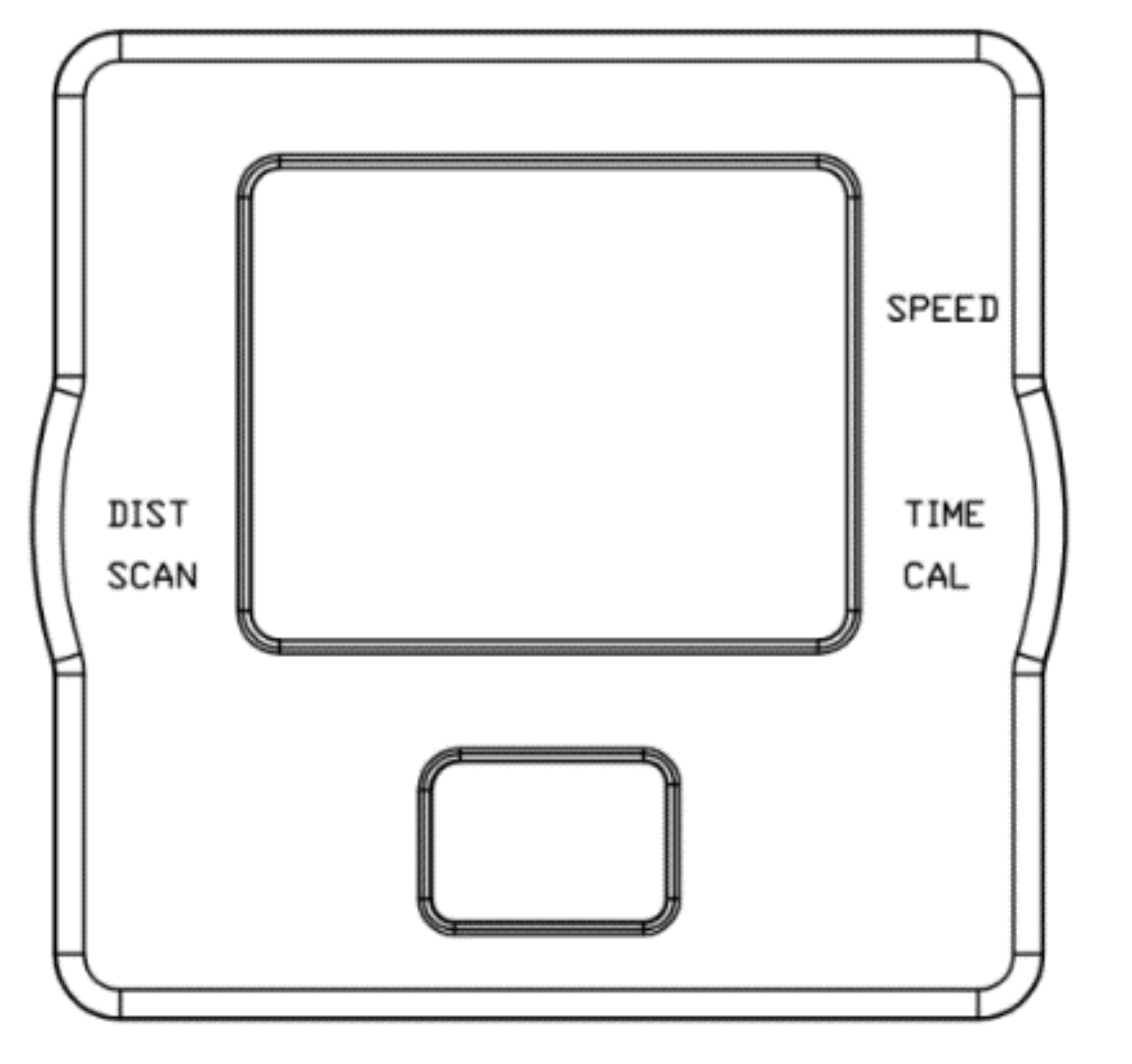
SPEED-----------------------------------------0.0~999.9 MPH (Mile/Hour)
TIME--------------------------------------------0:00~99:59 MIN
DIST (DISTANCE)--------------------------0.0~9999 M (Mile)
CAL (CALORIES)---------------------------0.0~9999 KCAL
FUNCTION KEYS:
MODE: Press the red key repeatedly to select the desired value (TIME, SPEED, DISTANCE, CALORIES, SCAN). Hold the key for 4 seconds to have all function values reset (total reset).
FUNCTIONS:
SPEED: Displays current speed.
TIME: Counts the total time of the exercise from start to finish.
DIST (DISTANCE): Counts the distance of the exercise from start to finish.
CAL (CALORIES): Counts the total calories burned during an exercise from start to finish. SCAN: Displays functions automatically in the following order: TIME, CALORIES, and DISTANCE.
NOTE:
- Please use 1pc of BUTTON CELL LR44 1.5V battery as a power supply. If there is an abnormal display on the meter, please replace the battery.
- The meter will automatically power on when pedals are in motion or the MODE key is being pressed.
- The meter will automatically start calculating when exercise begins.
- All functions will automatically stop calculating with a “STOP” sign on the upper left corner of the meter when there is no movement for about 4 seconds; “STOP” sign will be off and the meter will automatically start calculating as soon as the machine is in motion.
- The meter will automatically shut off if there is no movement for 4 to 5 minutes.
ADJUSTMENTS & USAGE GUIDE
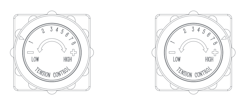
ADJUSTING THE TENSION
Adjust the tension by rotating the Tension Control Knob (No. 9) clockwise to increase the level of resistance. Rotate the Tension Control Knob (No. 9) counter-clockwise to decrease the level of resistance.
Tension levels are set at Level 1 being the lowest and Level 8 being the highest.
WARNING:
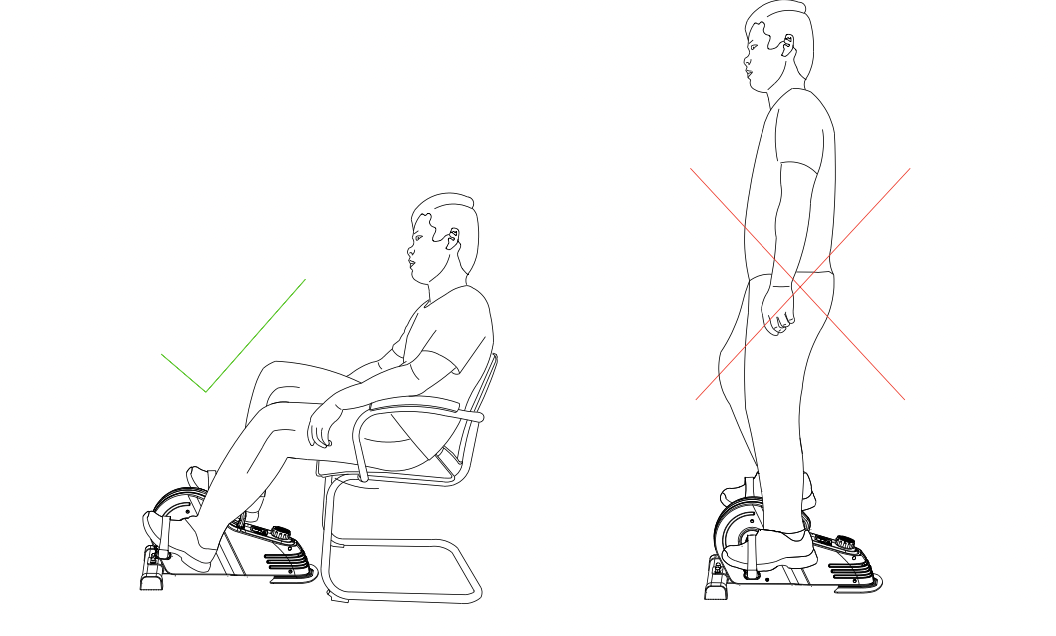
- The machine is intended to use in a sitting position only, do not stand on the machine.
- Failure to follow all warnings and instructions could result in serious injury or death.
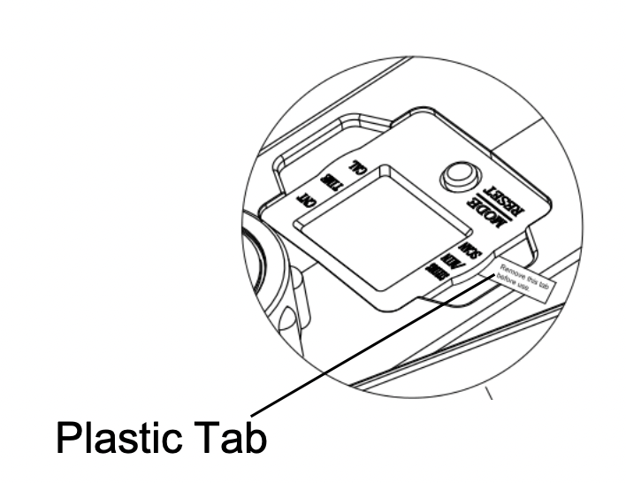
IMPORTANT NOTE: Please remove the plastic tab from the meter before use!
BATTERY INSTALLATION & REPLACEMENT
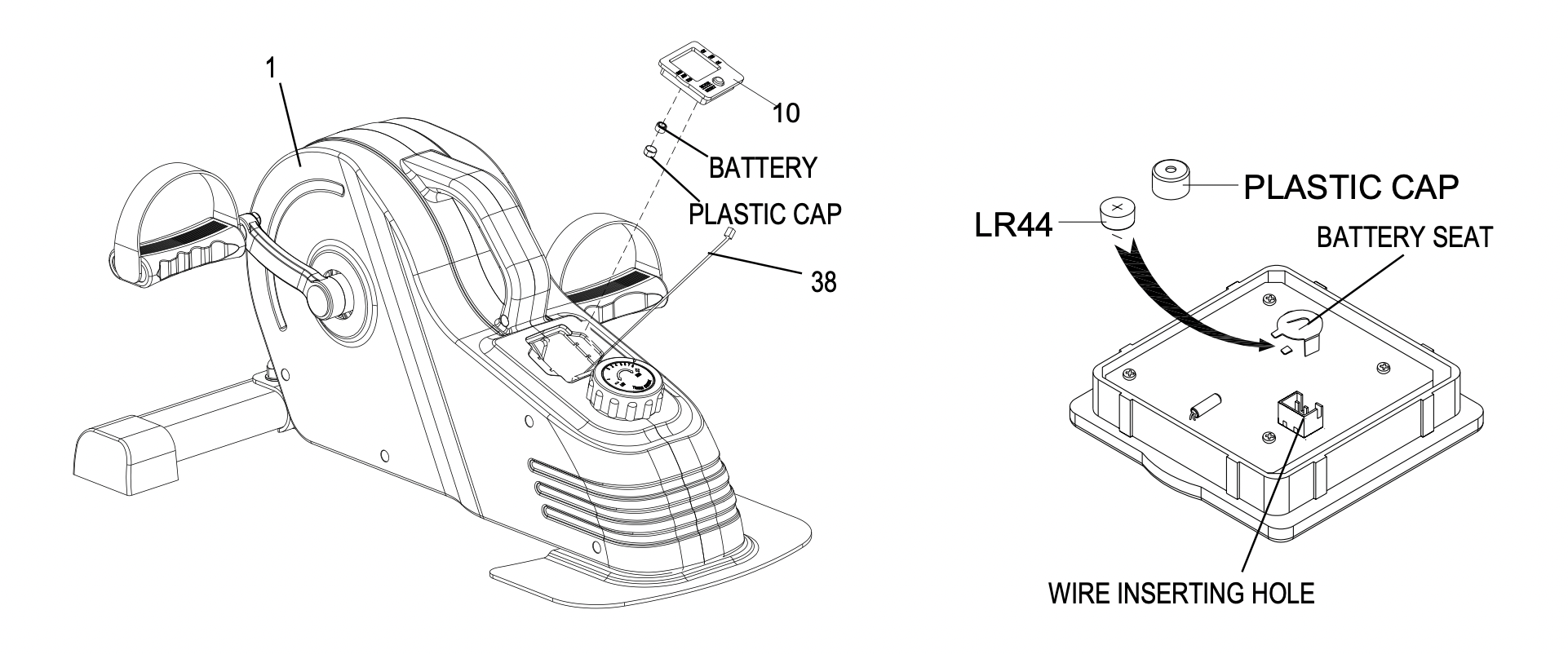
Remove the Meter (No. 10) from Main Frame (No. 1). Then disconnect the link wire of Inductor (No. 38) with the Meter (No. 10).
Remove the plastic cap from the back of Meter (No. 10).
Insert the battery using your fingers. Ensure that the positive side of the battery which is labeled with a + sign is facing upward once the battery is in place.
Put the plastic cap onto the battery seat.
Insert the link wire of Inductor (No. 38) into the hole on the back of Meter (No. 10).
Attach the Meter (No. 10) onto Main Frame (No. 1).