CONVERTIBLE WORKS RECUMBENT
BIKE
SF-RBD4703
USER MANUAL
English, Page 7~12 IMPORTANT! Please retain owner’s manual for maintenance and adjustment instructions. Your satisfaction is
very important to us, PLEASE DO NOT RETURN UNTIL YOU HAVE CONTACTED US:
support@sunnyhealthfitness.com or 1-877-90SUNNY (877-907-8669).
Español, Page 13~18 ¡IMPORTANTE! Por favor, conserve el manual del usuario para las instrucciones de mantenimiento y ajuste.
Su satisfacción es muy importante para nosotros, SI AL PRODUCTO LE HACE FALTA PARTES, POR
FAVOR NO LO DEVUELVA HASTA TENER CONTACTO CON NOSOTROS:
support@sunnyhealthfitness.com o al 1-877-90SUNNY (877-907-8669).

1
IMPORTANT SAFETY NOTICE
We thank you for choosing our product. To ensure your safety and health, please use this
equipment correctly. It is important to read this entire manual before assembling and using the
equipment. Safe and effective use can only be achieved if the equipment is assembled,
maintained and used properly. It is your responsibility to ensure that all users of the equipment are
informed of all warnings and precautions.
1. Before starting any exercise program, you should consult your physician to determine if you
have any medical or physical conditions that could put your health and safety at risk or prevent
you from using the equipment properly. Your physician’s advice is essential if you are taking
medication that affects your heart rate, blood pressure or cholesterol level.
2. Be aware of your body’s signals. Incorrect or excessive exercise can damage your health. Stop
exercising if you experience any of the following symptoms: pain, tightness in your chest,
irregular heartbeat, shortness of breath, lightheadedness, dizziness or feelings of nausea. If
you do experience any of these conditions, you should consult your physician before continuing
with your exercise program.
3. Keep children and pets away from the equipment. The equipment is designed for adult use
only.
4. Use the equipment on a solid, flat level surface with a protective cover for your floor or carpet.
To ensure safety, the equipment should have at least 4 feet (1.2 M) of free space all around it.
5. Ensure that all nuts and bolts are securely tightened before using the equipment. The safety of
the equipment can only be maintained if it is regularly examined for damage and/or wear and
tear.
6. Always use the equipment as indicated. If you find any defective components while assembling
or checking the equipment, or if you hear any unusual noises coming from the equipment
during exercise, discontinue use of the equipment immediately and do not use until the
problem has been rectified.
7. Wear suitable clothing while using the equipment. Avoid wearing loose clothing that may
become entangled in the equipment.
8. Do not place fingers or objects into the moving parts of the equipment.
9. The maximum weight capacity of this unit is 350 pounds (160 KG).
10. The equipment is not suitable for therapeutic use.
11. To avoid bodily injury and/or damage to the product or property, proper lifting and moving is
required.
12. Your product is intended for use in cool, dry conditions. You should avoid storage in extreme
cold, hot or damp areas as this may lead to corrosion and other related problems.
13. This equipment is designed for indoor and home use only, it is not intended for commercial use!

2
INFORMACIÓN IMPORTANTE DE SEGURIDAD
Gracias por haber elegido nuestro producto. Para garantizar su seguridad y salud, utilice este
equipo correctamente. Es importante que lea todo el manual antes de instalar y usar el equipo.
Sólo se puede lograr un uso seguro y eficaz si el equipo se ensambla, mantiene y se utiliza
correctamente. Es su responsabilidad asegurarse de que todos los usuarios conozcan todas las
advertencias y precauciones en los equipos.
1. Antes de comenzar algún programa de ejercicios, deberá consultar con su médico para
determinar si tiene alguna condición médica o física que pudiera poner en riesgo su salud y
seguridad o que pudiera impedir que utilice correctamente el equipo. Es importante que reciba
las recomendaciones de su médico en caso de que esté tomando un medicamento que afecte
su ritmo cardíaco, presión arterial o nivel de colesterol.
2. Esté atento a las señales que le envía su cuerpo. Ejercitarse de forma incorrecta o excesiva
puede perjudicar su salud. Deje de hacer ejercicio si experimenta alguno de los siguientes
síntomas: dolor, opresión en el pecho, latidos cardíacos irregulares, extrema falta de aire,
sensación de desmayo, mareos o sensación de náuseas. Si presenta alguna de esas
condiciones, deberá consultar con su médico antes de continuar con su programa de
ejercicios.
3. Mantenga el equipo alejado del alcance de los niños y mascotas. El equipo está diseñado para
el uso exclusivo de adultos.
4. Utilice el equipo en una superficie plana y sólida con una cubierta protectora para su piso o
alfombra. Para garantizar su seguridad, el equipo debe tener por lo menos 4 pies (120CM) de
espacio libre a su alrededor.
5. Asegúrese de que todas las tuercas y pernos estén bien ajustados antes de usar el equipo.
La seguridad del equipo solo puede ser mantenida si se inspecciona regularmente para
detectar daños o desgaste.
6. Siempre utilice el equipo como se indica. Si encuentra algún componente defectuoso mientras
instala o revisa el equipo, o si escucha ruidos extraños que provienen de este mientras se
ejercita, deje de utilizarlo inmediatamente y no lo utilice hasta que el problema se haya
rectificado.
7. Use ropa adecuada cuando utilice el equipo. Evite usar ropa suelta que pueda enredarse en el
equipo.
8. No coloque los dedos u objetos en las partes móviles del equipo.
9. La capacidad de peso máximo de esta unidad es de 350 libras (160KG).
10. El equipo no es adecuado para uso terapéutico.
11. Para evitar lesiones corporales y/o daños en el producto o en la propiedad, es necesario
levantar y mover el producto apropiadamente.
12. Su producto está diseñado para su uso en condiciones frescas y secas. Evite el
almacenamiento del producto en zonas extremadamente frías, calientes o húmedas, ya que
pueden provocar corrosión y otros problemas relacionados.
13. Este equipo está diseñado únicamente para uso interior y doméstico; no está diseñado para
uso comercial.
3
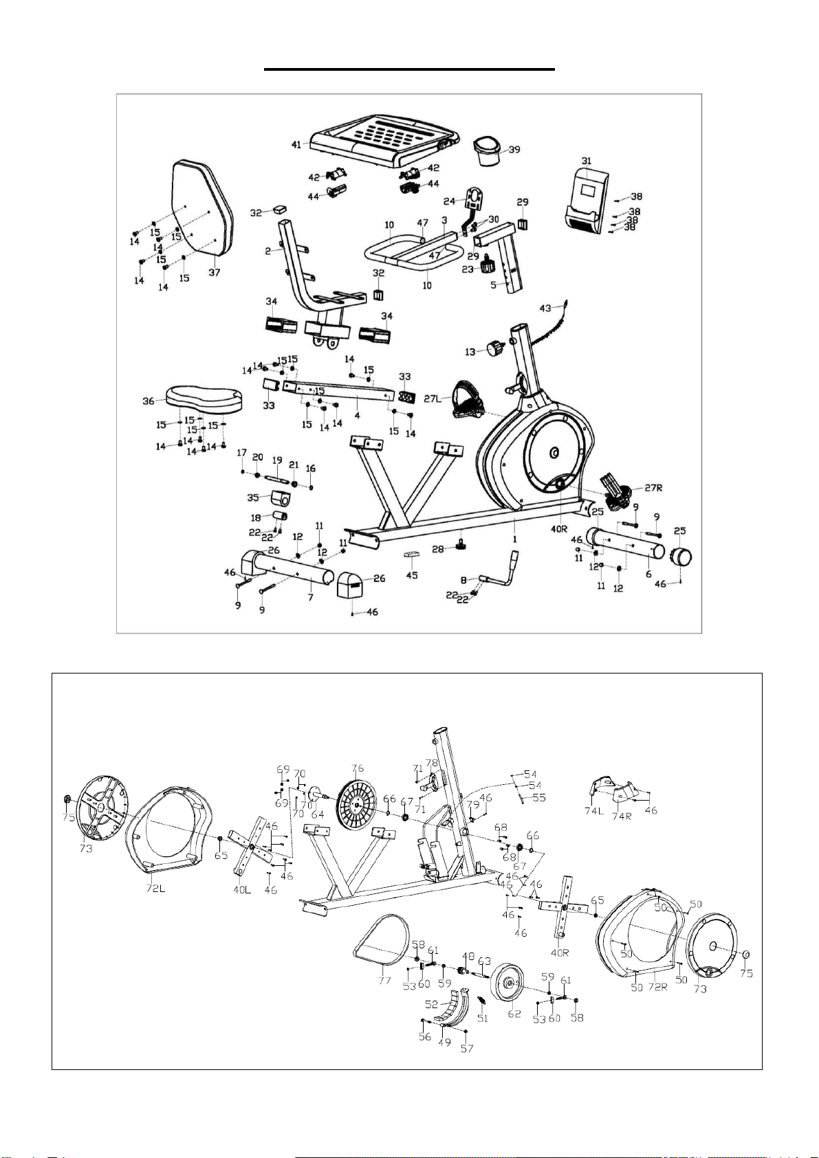
EXPLODED DIAGRAM

4
PARTS LIST
No.
Description
Spec.
Qty.
No.
Description
Spec.
Qty.
1
Main Frame
1
42
Fixing Bracket
2
2
Seat Post
1
43
Sensor Wire
1
3
Handlebar
1
44
Clamping Sheet
2
4
Slide Rail
1
45
Square Plug
60x30x1.5
1
5
Handlebar Post
1
46
Cross Pan Head Screw
ST4.2x18
23
6
Front Stabilizer
1
47
Round Plug
2
7
Rear Stabilizer
1
48
Small Belt Pulley
1
8
Adjustment Handle
1
49
Magnetic Board
1
9
Square Neck Bolt
M8xL73
4
50
Cross Pan Head Screw
ST4.2x30
5
10
Foam Grip
2
51
Spring Tension
1
11
Ball Cap Nut
M8
4
52
Square Magnet
8
12
Arc Washer
Ф8.2x2xФ19xr
30
4
53
Nut
M6
2
13
Spring Knob
1
54
Nut
M5
2
14
Hex Pan Head Screw
M8x16
14
55
Hex Bolt
M5x60
1
15
Washer
D8x1.5xФ16
14
56
Hex Bolt
M8xL60x120
1
16
Spring Stop Collar
D12
1
57
Nylon Nut
M8
1
17
Spring Stop Collar
D10
1
58
Flange Nut
M10x1
2
18
Eccentric Gear
1
59
Conical Thin Nut
M10x1xH5
2
19
Axle
1
60
Adjustable Chain U Mat
2
20
Small Alloy Bushing
1
61
Guide Bolt
2
21
Big Alloy Bushing
1
62
Flywheel
1
22
Hex Socket Cap Screw
M6x10
4
63
Flywheel Axle
1
23
Spring Knob
1
64
Middle Axle
1
24
Computer Bracket
1
65
Flange Nut
M10x1.25
2
25
Wheeled End Cap
2
66
Spring Stop Collar
2
26
Horseshoe-Shaped End
Cap
2
67
Bearing
6003RZ
2
27L/R
Pedal
1pr.
68
Hex Socket Cap Screw
M6x15
4
28
Adjustable Pad
1
69
Nylon Nut
M6
4
29
Bushing
2
70
Spring Washer
D6
4
30
Cross Pan Head Screw
M6x10
2
71
Cross Pan Head Screw
M5x12
2
31
Computer
1
72L/R
Chain Cover
1 pr.
32
Square Plug
38x38x1.5
2
73
Turn Plate
2
33
Square Plug
80x40x2
2
74L/R
Protective Cover
1 pr.
34
Bushing
2
75
Nut Cover
2
35
Upper Holder Block
1
76
Big Belt Pulley
1
36
Seat
1
77
Flat Belt
1
37
Backrest
1
78
Tension Control
1
38
Cross Pan Head Screw
M5x12
4
79
Sensor
1
39
Bottle Holder
1
80
Spanner
S=13、14、15
1
40L/R
Crank
1pr.
81
Wrench
S= 5
1
41
Desk
1
82
Wrench
S= 6
1

5
LISTA DE PARTES
n.°
Descripción
Espec.
Cant.
n.°
Descripción
Espec.
Cant.
1
Estructura Principal
1
42
Soporte para Fijación
2
2
Tija de Sillín
1
43
Cable del Sensor
1
3
Manubrio
1
44
Pieza de Sujeción
2
4
Riel Deslizante
1
45
Clavija Cuadrada
60x30x1.5
1
5
Poste del Manubrio
1
46
Tornillo
ST4.2x18
23
6
Estabilizador Delantero
1
47
Clavija Redonda
2
7
Estabilizador Trasero
1
48
Polea Pequeña de Correa
1
8
Palanca de Ajuste
1
49
Tablero Magnético
1
9
Perno de Cuello Cuadrado
M8xL73
4
50
Tornillo
ST4.2x30
5
10
Agarre de Espuma
2
51
Resorte de Tensión
1
11
Tuerca Ciega
M8
4
52
Imán Cuadrada
8
12
Arandela
Ф8.2x2xФ19
xr30
4
53
Tuerca
M6
2
13
Perilla de Resorte
1
54
Tuerca
M5
2
14
Tornillo de Cabeza
Hexagonal
M8x16
14
55
Perno Hexagonal
M5x60
1
15
Arandela
D8x1.5xФ16
14
56
Perno Hexagonal
M8xL60x120
1
16
Tope de Resorte
D12
1
57
Tuerca de Nylon
M8
1
17
Tope de Resorte
D10
1
58
Tuerca
M10x1
2
18
Engranaje
1
59
Tuerca
M10x1xH5
2
19
Eje
1
60
Arandela Ajustable de
Forma U
2
20
Buje de Aleación Pequeña
1
61
Perno de Guía
2
21
Buje de Aleación Grande
1
62
Volante de Inercia
1
22
Tornillo de Cabeza
Hexagonal
M6x10
4
63
Eje de Volante de Inercia
1
23
Perilla de Resorte
1
64
Eje Medio
1
24
Soporte del Monitor
1
65
Tuerca
M10x1.25
2
25
Tapa de Extremo con
Ruedas
2
66
Tope de Resorte
2
26
Tapones en Forma de U
2
67
Cojinete
6003RZ
2
27L/R
Pedal
1 par.
68
Tornillo de Cabeza
Hexagonal
M6x15
4
28
Nivelador
1
69
Tuerca de Nylon
M6
4
29
Bushing
2
70
Arandela de Presión
D6
4
30
Tornillo
M6x10
2
71
Tornillo
M5x12
2
31
Monitor
1
72L/R
Cubierta de Cadena
1 par.
32
Clavija Cuadrada
38x38x1.5
2
73
Disco de Girar
2
33
Clavija Cuadrada
80x40x2
2
74L/R
Cubierta Protectora
1 par.
34
Buje
2
75
Cubierta de Tuerca
2
35
Bloque de Soporte
Superior
1
76
Polea Grande de Correa
1
36
Asiento
1
77
Correa
1
37
Respaldo
1
78
Controlador de Tensión
1
38
Tornillo
M5x12
4
79
Sensor
1
39
Porta Botellas
1
80
Llave Inglesa
S=13、14、15
1
40L/R
Biela
1 par.
81
Llave Allen
S= 5
1
41
Tablero
1
82
Llave Allen
S= 6
1
6
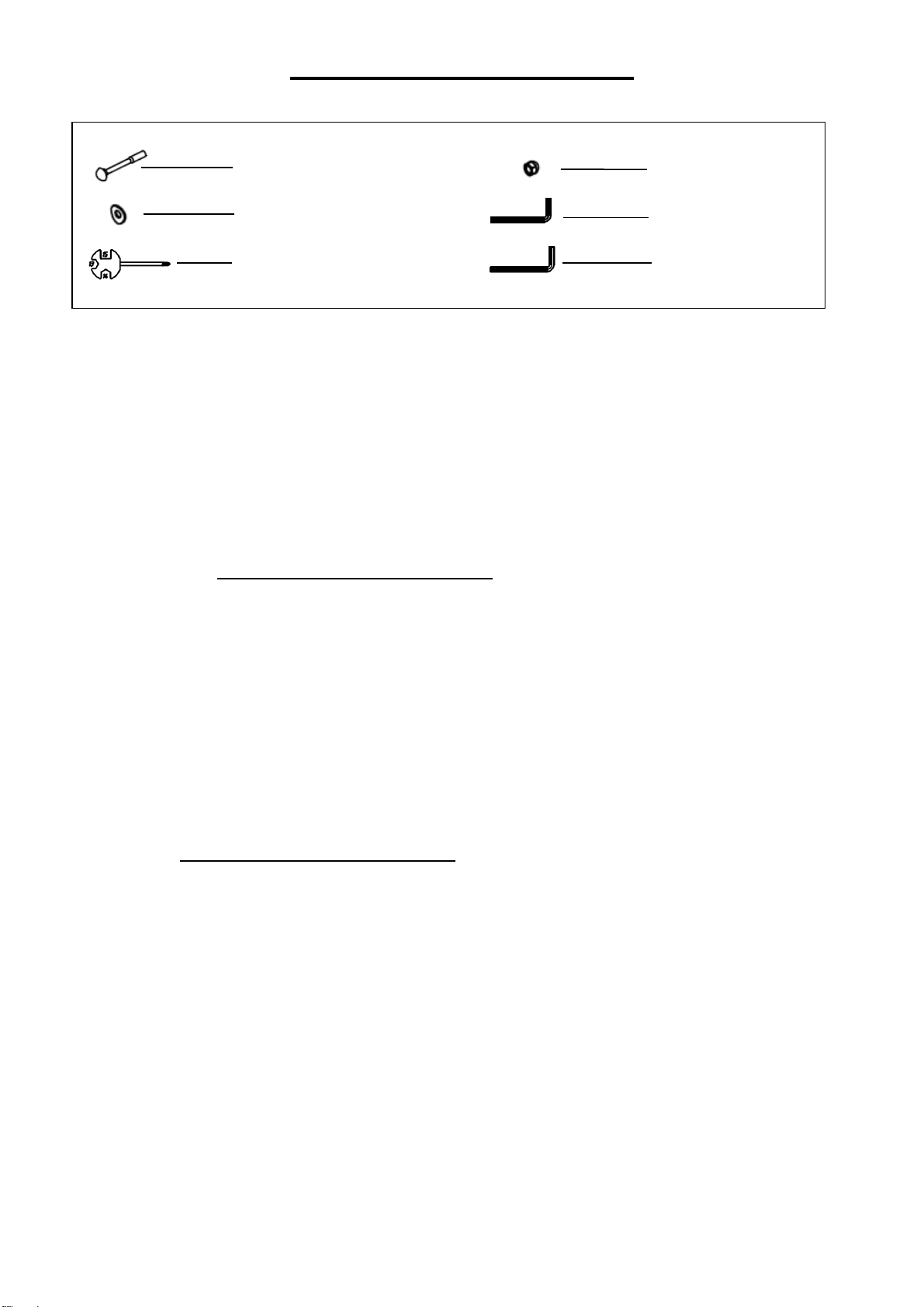
HARDWARE PACKAGE
Ordering Replacement Parts (U.S. and Canadian Customers only)
Please provide the following information in order for us to accurately identify the part(s) needed:
✓ The model number (found on cover of manual)
✓ The product name (found on cover of manual)
✓ The part number found on the “EXPLODED DIAGRAM” and “PARTS LIST” (found near the
front of the manual)
Please contact us at [email protected] or 1- 877 – 90SUNNY (877-907-8669).
Pedido de piezas de repuesto (solo para clientes de EE. UU. y Canadá)
Proporcione la siguiente información para que podamos identificar con precisión las piezas
necesarias:
✓ El número de modelo (se encuentra en la portada del manual).
✓ El nombre del producto (se encuentra en la portada del manual).
✓ El número de pieza que se encuentra en el “ESQUEMA DE LAS PIEZAS” y en la “LISTA
DE PIEZAS” (se encuentra al principio del manual).
Contáctenos en [email protected] o 1- 877 - 90SUNNY (877-907-8669).
#9 M8*L73 4PCS
#12 Ф8.2*2*Ф19*R30 4PCS
#80 S=13、14、15 1PC
#11 M8 4PCS
#81 S=5 1PC
#82 S=6 1PC
7
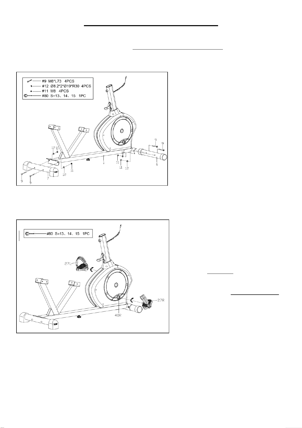
ASSEMBLY INSTRUCTIONS
We value your experience using Sunny Health and Fitness products. For assistance with parts or
(877-907-8669).
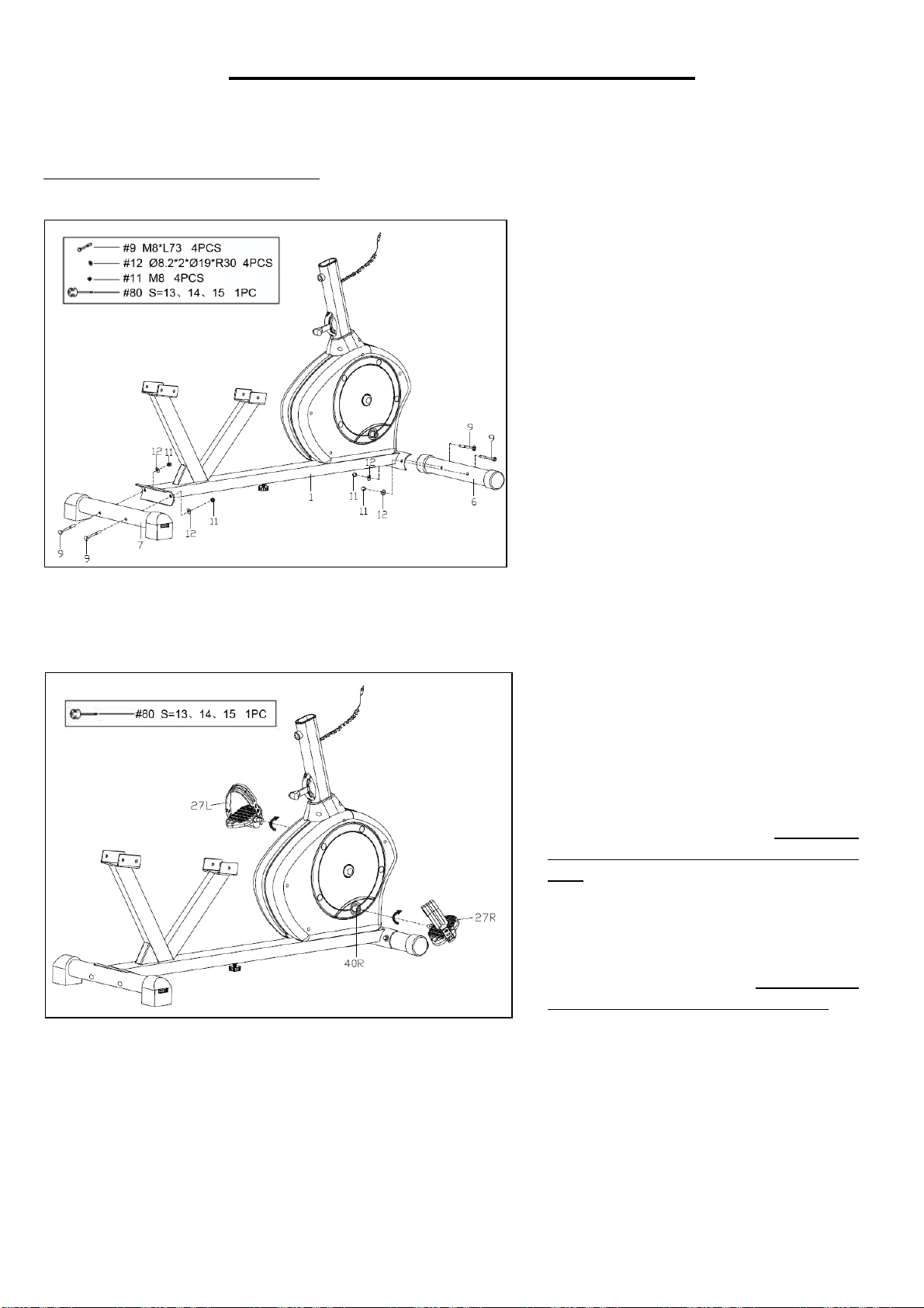
STEP 1:
Attach Front Stabilizer (No. 6) and
Rear Stabilizer (No. 7) to Main
Frame (No. 1) with 4 Square Neck
Bolts (No. 9), 4 Arc Washers (No.
12) and 4 Ball Cap Nuts (No. 11)
with Spanner (No. 80).
STEP 2:
Attach the 2 Pedals (No. 27L/R) to
Cranks (No. 40L/R).
NOTE: Make sure to attach Right
Pedal (No. 27R), marked (R), to the
Right Crank (No. 40R). It should be
tightened clockwise. Attach the Left
Pedal (No. 27L), marked (L), to the
Left Crank (No. 40L). It should be
tightened counter-clockwise.
Attaching the Pedals (No. 27L/R) to
the wrong Cranks (No. 40L/R) or
turning it the wrong direction can
damage the Cranks (No. 40L/R).
T
i
g
h
t
e
n
b
y
h
a
n
8
We value your experience using Sunny Health and Fitness products. For assistance with parts or
(877-907-8669).
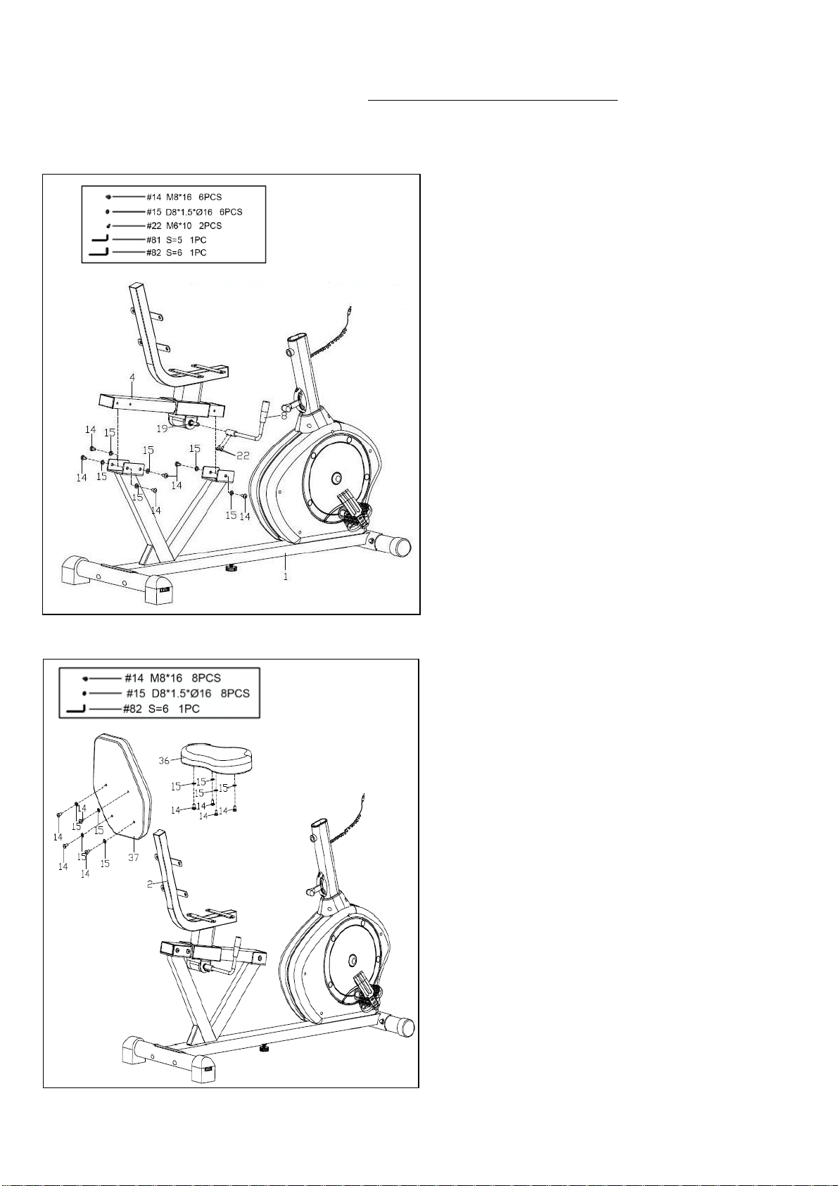
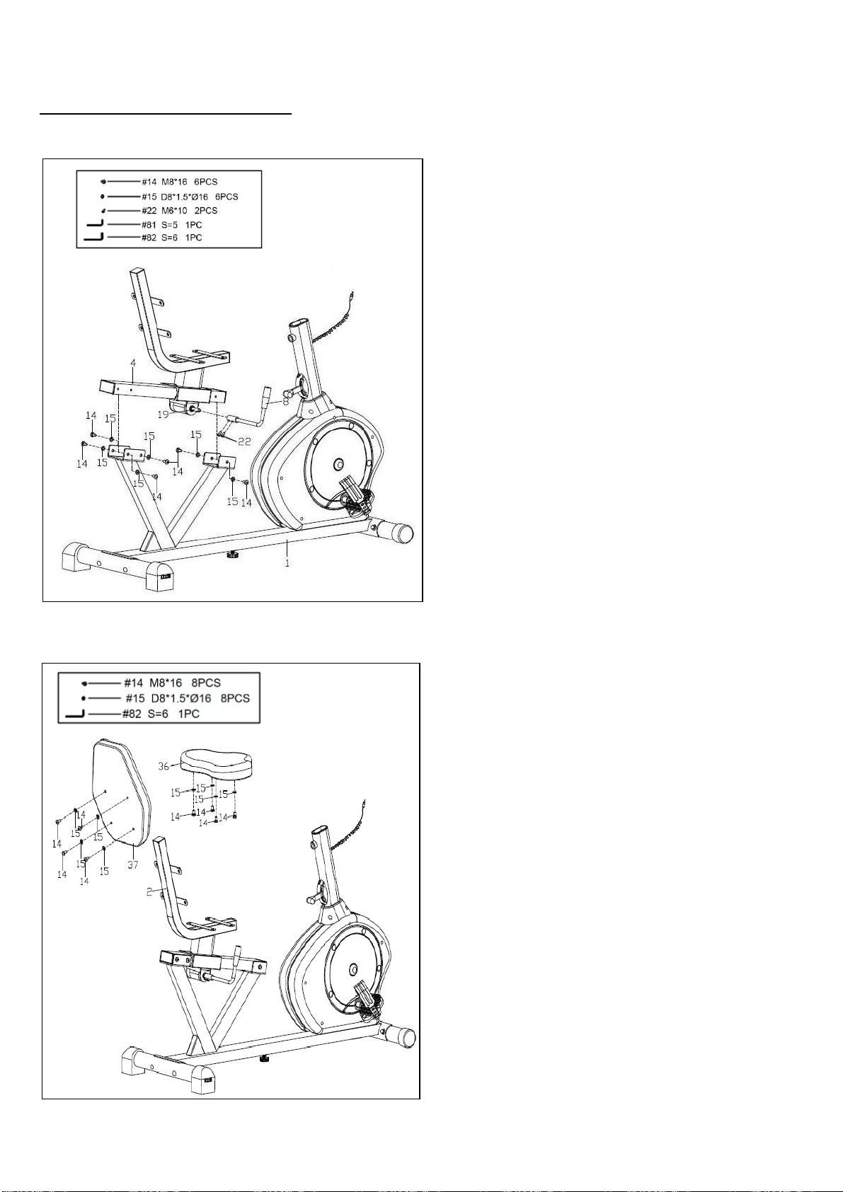
STEP 3:
Remove preassembled 6 Hex Pan Head
Screws (No. 14) and 6 Washers (No. 15)
from the Slide Rail (No. 4) first. Then
attach the Slide Rail (No. 4) to the Main
Frame (No. 1) with the 6 Hex Pan Head
Screws (No. 14) and 6 Washers (No. 15)
and tighten with Wrench (No. 82).
Remove the preassembled 2 Hex Socket
Cap Screws (No. 22) from Axle (No. 19)
first. Then attach the Adjustment Handle
(No. 8) to Axle (No. 19) with 2 Hex Socket
Cap Screws (No. 22), and secure tightly
with Wrench (No. 81). Make sure the
Adjustment Handle (No. 8) is pointing up.
STEP 4:
Remove preassembled 4 Hex Pan Head
Screws (No. 14) and 4 Washers (No. 15)
from Backrest (No. 37). Then attach the
Backrest (No. 37) to Seat Post (No. 2)
tightly with 4 Hex Pan Head Screws (No.
14) and 4 Washers (No. 15). Tighten with
Wrench (No. 82).
Remove preassembled 4 Hex Pan Head
Screws (No. 14) and 4 Washers (No. 15)
from Seat (No. 36). Then attach the Seat
(No. 36) to Seat Post (No. 2) tightly with 4
Hex Pan Head Screws (No. 14) and 4
Washers (No. 15). Tighten with Wrench
(No. 82).
9
We value your experience using Sunny Health and Fitness products. For assistance with parts or
(877-907-8669).
I
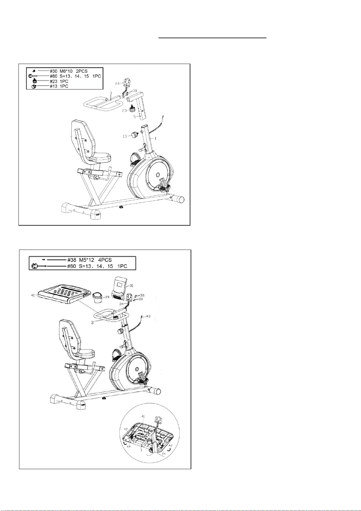
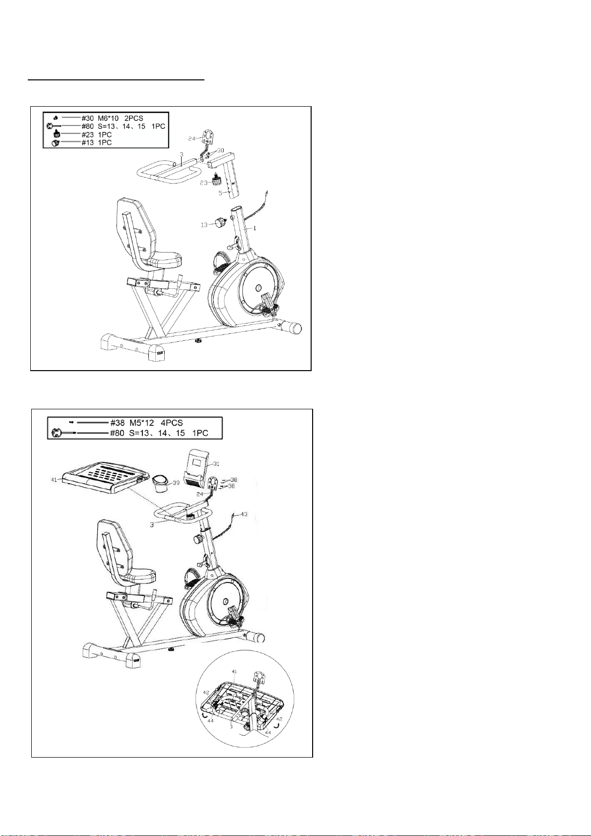
STEP 5
Insert Handlebar Post (No. 5) into front
tube of Main Frame (No. 1), and secure
tightly with Spring Knob (No. 13).
Insert the Handlebar (No. 3) into
horizontal tube of Handlebar Post (No.
5), and secure tightly with the Spring
Knob (No. 23).
Remove the preassembled 2 Cross Pan
Head Screws (No. 30) from Handlebar
(No. 3). Then attach Computer Bracket
(No. 24) to the Handlebar (No. 3) with 2
Cross Pan Head Screws (No. 30), and
secure tightly with Spanner (No. 80).
STEP 6
Install the Desk (No. 41) onto Handlebar
(No. 3). Handlebar (No. 3) should fit in
the grooves on bottom of Desk (No. 41).
To secure desk, close the clasps. See
Figure A. Attach the Bottle Holder (No.
39) to the Desk (No. 41).
Remove the preassembled 4 Cross Pan
Head Screws (No. 38) from the back of
the Computer (No. 31). Then secure
Computer (No. 31) to the Computer
Bracket (No. 24) with 4 Cross Pan
Head Screws (No. 38) using Spanner
(No. 80). Insert Sensor Wire (No. 43)
into hole on the back of Computer (No.
31).
The assembly is now complete!
Figure A
10
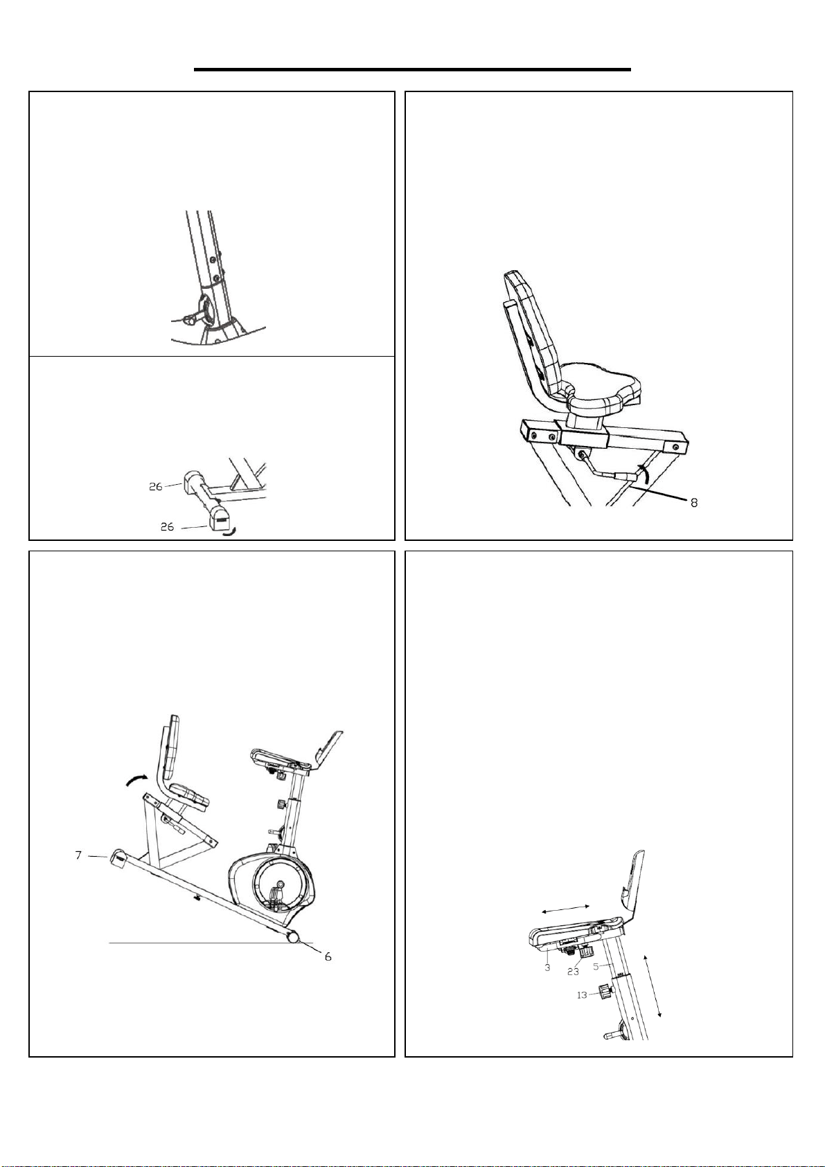
ADJUSTMENTS & USAGE GUIDE
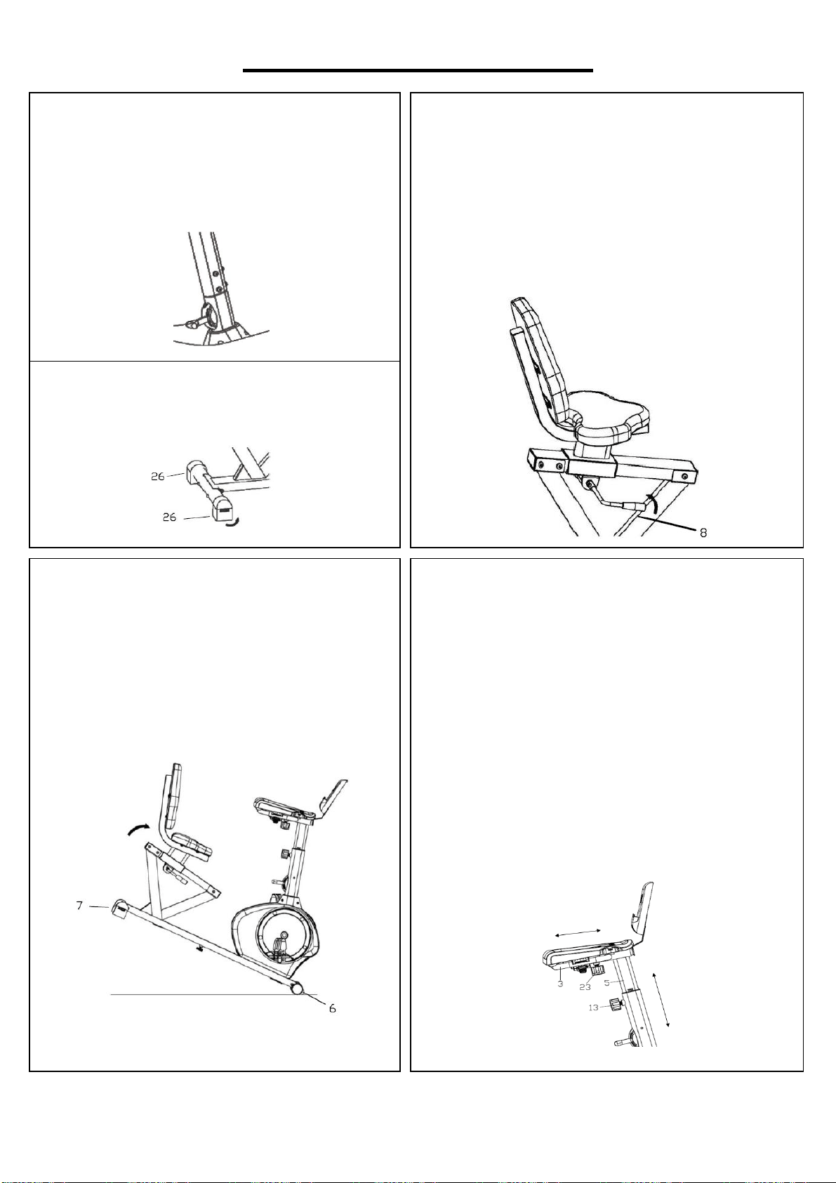
MOVING THE BIKE
Lift the bike by the Rear Stabilizer (No. 7)
until the wheels on the Front Stabilizer (No.
6) touch the floor. Now you can move the bike.
ADJUSTING THE SEAT POSITION
To move the seat forward or backward seat on
the bike and pull the Adjustment Handle (No. 8)
towards you. Move the seat to desired position
and push the Adjustment Handle (No. 8)
forward to secure.
ADJUSTING THE TENSION
To adjust the tension of the bike, move
Tension Switch A. 1 is the lowest tension
setting. 8 is the highest tension setting.
A
ADJUSTING THE LEVEL
If the bike is not level, adjust the
Horseshoe-shaped End Caps (No. 26).
ADJUSTING THE DESK
You can adjust the position of the desk by
adjusting the Handlebar (No. 3) and the
Handlebar Post (No. 5).
To move the Handlebar (No. 3) forward or
backward, loosen and pull on Spring Knob (No.
23) and move the Handlebar (No. 3) to desired
position. Set the Spring Knob (No. 23) in one of
the holes and tighten.
To move the Handlebar Post (No. 5) up or
down, loosen and pull on Spring Knob (No. 13)
and move Handlebar Post (No. 5) to desired
height. Set the Spring Knob (No. 13) in one of
the holes and tighten.
11
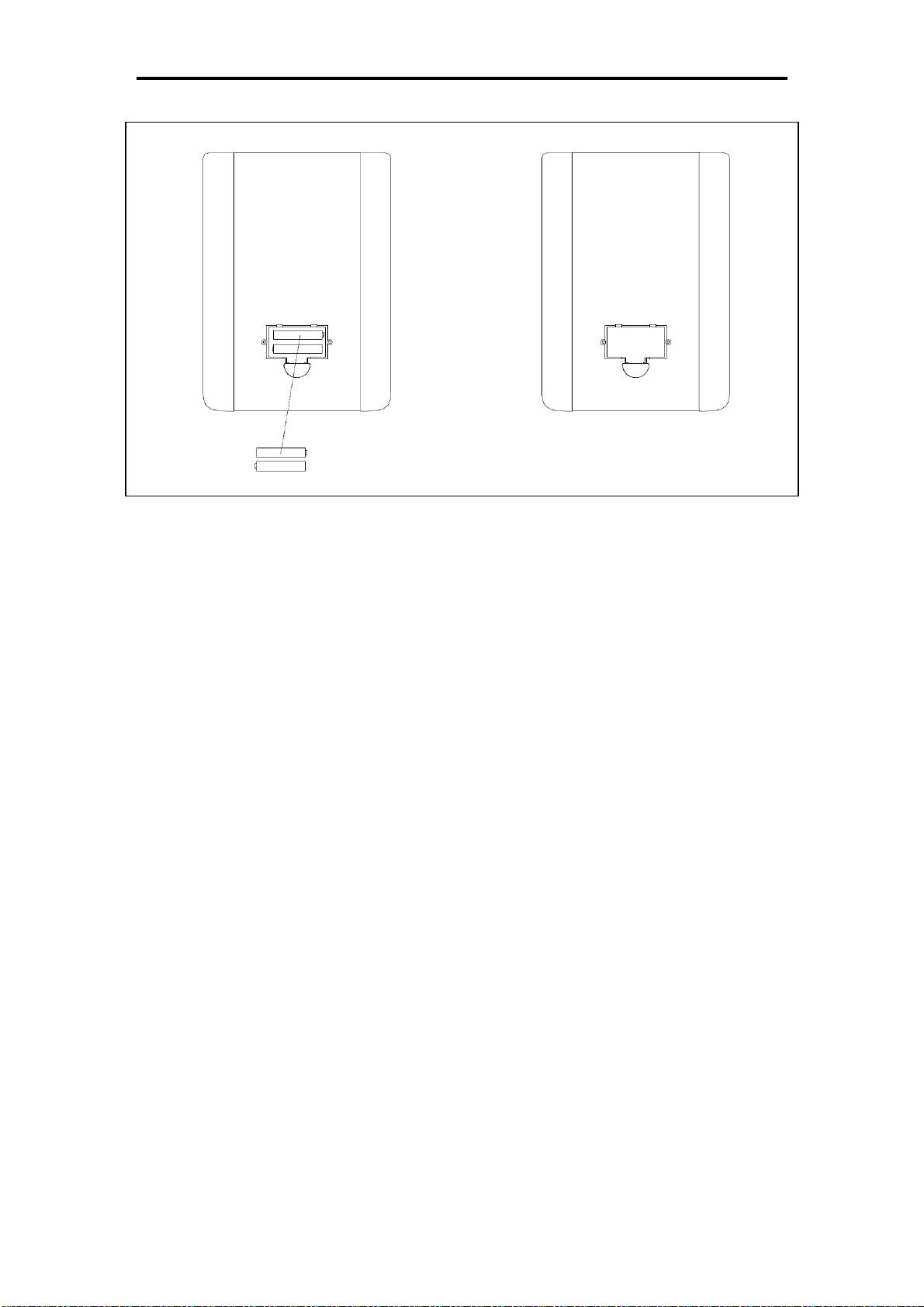
BATTERY INSTALLATION & REPLACEMENT
BATTERY INSTALLATION
The computer uses 2 AAA batteries. Open the battery cover from the back of computer, then put 2
batteries into the battery compartment. Make sure the (+) and (-) ends of the batteries are in the
correct position. Put the battery cover back.
BATTERY REPLACEMENT
If there is a problem with the display, try changing the batteries first. Open the battery cover,
remove the old batteries, and replace with new batteries. Make sure the (+) and (-) ends of the
batteries are in the correct position. Put the battery cover back.
When changing batteries, always replace both with new batteries. Do not mix old and new
batteries.

12
EXERCISE COMPUTER
SPECIFICATIONS:
TIME……………………………………………………..…00:00-99:59
SPEED (SPD) ……………………………………..……0.0-99.9MPH
DISTANCE (DIST)………………………………………0.00-999.9ML
CALORIE (CAL)………………………………………0.00-9999KCAL
ODOMETER (ODO)………………………………………0.0-9999ML
KEY FUNCTION:
MODE (SELECT/RESET): This allows user to select the desired
function (Scan, Time, Speed. Dist, Odo, and Cal). The arrow will
point to the function chosen.
AUTO ON/OFF:
The computer turns on when any key is pressed, or when user starts pedaling. The computer turns
off automatically when there has been no activity or keys pressed for approximately 4 minutes.
RESET:
The computer can be reset by either changing the battery or pressing and holding the MODE key
for 3 seconds. ODOMETER will not be reset.
MODE:
Used to choose SCAN or LOCK. If you do not want the SCAN mode, press the MODE key when
the pointer is blinking and on the function you want.
FUNCTIONS:
SCAN: Automatically display functions in the following order: Time, Speed, Dist, Odo, and Cal
every 4 seconds.
TIME: Press MODE key until arrow points to TIME. The total working time will be shown.
SPEED: Press MODE key until the arrow points to SPEED. The current speed will be shown.
DISTANCE: Press MODE key until the arrow points to DISTANCE. Distance will be displayed.
CALORIE: Press MODE key until arrow points to CALORIE. The calories burned will be displayed.
ODOMETER: Press MODE key until arrow points to ODOMETER. Total accumulated distance will
be displayed.
BATTERY DISPOSAL: The computer uses 2 AAA batteries, which are included in computer box.
Dispose the batteries according to the laws and regulations of your local region. Some batteries
may be recycled. When disposing or recycling, do not mix battery types.
Version 1.11
13
INSTRUCCIONES DE MONTAJE
Valoramos su experiencia con los productos de Sunny Health and Fitness. Para obtener ayuda con
las piezas o resolver algún problema, escríbanos a la dirección de correo
PASO 1:
Conecte el Estabilizador Delantero
(n.° 6) y el Estabilizador Trasero
(n.° 7) a la Estructura Principal (n.°
1) con los 4 Pernos de Cuello
Cuadrado (n.° 9), 4 Arandelas (n.°
12) y las 4 Tuercas Ciegas (n.° 11)
usando la Llave Inglesa (n.° 80).
PASO 2:
Conecte los 2 Pedales (n.° 27L/R) a
las Bielas (n.° 40L/R).
NOTA: Asegúrese de conectar el
Pedal Derecho (n.° 27R), marcado
en (R), a la Biela Derecha (n.° 40R).
Se debe apretarse hacia el sentido
del movimiento de las agujas del
reloj.
Conecte el Pedal Izquierdo (n.°
27L), marcado en (L), a la Biela
Izquierda (n.° 40L). Se debe
apretarse en sentido contrario al
movimiento de las agujas del reloj.
IMPORTANTE: Si se conectan los
Pedales (n.° 27L/R) a las Bielas (n.°
40L/R) equivocadamente o se gira
en el sentido contrario, se podrían
causar daños a las Bielas (n.°
40L/R).
T
i
g
h
t
14
Valoramos su experiencia con los productos de Sunny Health and Fitness. Para obtener ayuda con
las piezas o resolver algún problema, escríbanos a la dirección de correo
PASO 3:
Desatornille primero los 6 Tornillos de
Cabeza Hexagonal (n.° 14) y las 6
Arandelas (n.° 15) preensambladas al
Riel Deslizante (n.° 4).
Luego, conecte el Riel Deslizante (n.°
4) a la Estructura Principal (n.° 1) con
los 6 Tornillos de Cabeza Hexagonal
(n.° 14) y las 6 Arandelas (n.° 15) y
apriételos con la Llave Allen (n.° 82).
Desatornille después los 2 Tornillos de
Cabeza Hexagonal (n.° 22)
preensamblados en el Eje (n.° 19). A
partir de ahí, conecte la Palanca de
Ajuste (n.° 8) al Eje (n.° 19), y
asegúrelo firmemente con los 2
Tornillos de Cabeza Hexagonal (n.°
22), apriételos con la Llave Allen (n.°
81). Asegúrese de que la Palanca de
Ajuste (n.° 8) esté apuntando hacia
arriba.
PASO 4:
Desatornille los 4 Tornillos de Cabeza
Hexagonal (n.° 14) y las 4 Arandelas
(n.° 15) preensambladas en la parte del
Respaldo (n.° 37). Luego conecte la
parte del Respaldo (n.° 37) hacia la
Tija de Sillín (n.° 2) firmemente con los
4 Tornillos de Cabeza Hexagonal (n.°
14) y las 4 Arandelas (n.° 15). Atornille
el proceso con una Llave Allen (n.° 82).
Desatornille los 4 Tornillos de Cabeza
Hexagonal (n.° 14) y las 4 Arandelas
(n.° 15) preensambladas en la parte del
Asiento (n.° 36). Después, posicione y
conecte firmemente la parte del Asiento
(n.° 36) a la Tija de Sillín (n.° 2) con los
4 Tornillos de Cabeza Hexagonal (n.°
14) y las 4 Arandelas (n.° 15) usando
la Llave Allen (n.° 82).
15
Valoramos su experiencia con los productos de Sunny Health and Fitness. Para obtener ayuda con
las piezas o resolver algún problema, escríbanos a la dirección de correo
I
PASO 5:
Inserte el Poste del Manubrio (n.° 5) a la
Estructura Principal (n.° 1), y asegúrelo
firmemente con la parte de la Perilla de
Resorte (n.° 13).
Inserte el Manubrio (n.° 3)
horizontalmente a la parte del Poste del
Manubrio (n.° 5), y asegúrelo firmemente
con la Perilla de Resorte (n.° 23).
Desatornille los 2 Tornillos (n.° 30)
preensamblados a la parte del Manubrio
(n.° 3). Luego, conecte el Soporte del
Monitor (n.° 24) al Manubrio (n.° 3) con
los 2 Tornillos (n.° 30), y asegúrelos
firmemente usando una Llave Inglesa
(n.° 80).
PASO 6:
Instale el Tablero (n.° 41) en la parte del
Manubrio (n.° 3). La parte del Manubrio
(n.° 3) debe encajar con las ranuras de la
parte inferior del Tablero (n.° 41). Para
asegurar el tablero, cierre los enganches
plásticos. Ver Figura A. Conecte el Porta
botellas (n.° 39) con el Tablero (n.° 41).
Desatornille los 4 Tornillos (n.° 38)
preensamblados de la parte trasera del
Monitor (n.° 31). Luego asegure el
Monitor (n.° 31) a la parte del Soporte
del Monitor (n.° 24) con los 4 Tornillos
(n.° 38) usando la Llave Inglesa (n.° 80).
Inserte el Cable del Sensor (n.° 43) al
orificio de la parte posterior del Monitor
(n.° 31).
¡La instalación ha sido completada!
Figure A
16
AJUSTES Y GUÍA DE USO
MOVIENDO LA BICICLETA
Levante la bicicleta por la parte del
Estabilizador Trasero (n.° 7) hasta que las
ruedas del Estabilizador Delantero (n.° 6)
toquen el suelo. Ahora puede mover la
bicicleta a la ubicación deseada con facilidad.
AJUSTANDO LA POSICION DEL ASIENTO
Para mover el asiento hacia adelante o hacia
atrás, siéntese en la bicicleta, jale la Palanca de
Ajuste (n.° 8) hacia usted. Mueve el asiento a la
posición deseada y empuje la Palanca de Ajuste
(n.° 8) hacia adelante para asegurar su posición.
.
AJUSTANDO LA TENSIÓN
Para ajustar la tensión de la bicicleta, mueva
la Palanca de la Tensión A. 1 es el ajuste de
tensión más bajo. 8 es el ajuste de tensión
más alto.
A
AJUSTANDO EL NIVEL
Si la bicicleta no se encuentra nivelada, ajuste
los Tapones en Forma de U (n.° 26).
AJUSTANDO EL TABLERO
Puede ajustar la posición del tablero ajustando el
Manubrio (n.° 3) y el Poste del Manubrio (n.° 5).
Para ajustar el Manubrio (n.° 3) hacia adelante o
hacia atrás, afloje y jale la Perilla de Resorte (n.°
23) y mueva el Manubrio (n.° 3) a la posición
deseada. Acomode la Perilla de Resorte (n.° 23)
en uno de los orificios y asegúrela para
asegurarla a su posición deseada.
Para ajustar el Poste del Manubrio (n.° 5) hacia
arriba o hacia abajo, afloje y jale la Perilla de
Resorte (n.° 13) y mueva el Poste del Manubrio
(n.° 5) a la altura deseada. Coloque la Perilla de
Resorte (n.° 13) en uno de los orificios para
asegurarla a su posición deseada.

17
INSTALACIÓN Y REMPLAZO DE BATERIA
INSTALACIÓN DE LA BATERÍA
El ordenador utiliza 2 baterías AAA. Abra la tapa del compartimento de las baterías desde la parte
trasera del ordenador y coloque 2 baterías en el compartimento. Asegúrese de que las terminales
(+) y (-) de las baterías estén en la posición correcta. Cubra su tapa una vez colocada las
baterías.
SUSTITUCIÓN DE LA BATERÍA
Si hay un problema con la pantalla, intente cambiar las baterías primero. Abra la tapa del
compartimiento de las pilas, retire las baterías antiguas y sustitúyalas por las nuevas. Asegúrese
de que las terminales (+) y (-) de las baterías estén en la posición correcta. Cubra su tapa una vez
colocadas
Cuando cambie las baterías, sustitúyalas siempre por otras nuevas. No se recomienda combinar
las baterías antiguas con las nuevas.

18
ORDENADOR
ESPECIFICACIONES:
TIEMPO………………………………………………….…00:00-99:59
VELOCIDAD (SPD) ………………………………….….0.0-99.9MPH
DISTANCIA (DIST)…………………………………… 0.00-999.9ML
CALORIAS (CAL)…………………..……………… 0.00-9999KCAL
ODOMETRO (ODO)………………………………………0.0-9999ML
FUNCIONES PRINCIPALES:
MODO (SELECCIONAR/RESET): Permite al usuario seleccionar la
función deseada (Scan, Time, Speed. Dist, Odo, y Cal). La flecha
señala la función elegida.
ENCENDIDO / APAGADO AUTOMÁTICO:
El ordenador se enciende cuando se pulsa cualquier tecla o cuando el usuario comienza a
pedalear. El ciclo-computador se apaga automáticamente cuando no hay actividad o no se pulsan
las teclas durante aproximadamente 4 minutos.
RESET:
El ciclo-computador puede reiniciarse cambiando la batería o manteniendo pulsada la tecla MODE
durante 3 segundos. El ODÓMETRO no se reiniciará.
MODE:
Se utiliza para elegir SCAN o LOCK. Si no desea el modo SCAN, pulse la tecla MODE cuando el
puntero esté parpadeando y en la función que desee.
FUNCIONES:
SCAN: Muestra automáticamente las funciones en el siguiente orden: Hora, Velocidad, Dist, Odo
y Cal cada 4 segundos.
HORA: Pulse la tecla MODE hasta que la flecha señale TIME. Se mostrará el tiempo total de
trabajo.
VELOCIDAD: Presione la tecla MODE hasta que la flecha apunte a VELOCIDAD. Se mostrará la
velocidad actual.
DISTANCIA: Pulse la tecla MODE hasta que la flecha señale DISTANCIA. Se mostrará la
distancia.
CALORÍAS: Pulse la tecla MODE hasta que la flecha señale CALORÍAS. Se mostrarán las
calorías quemadas.
ODÓMETRO: Presione la tecla MODE hasta que la flecha apunte a ODÓMETRO. Se mostrará la
distancia total acumulada.
DISPOSICIÓN DE BATERIAS: El ciclo-computador utiliza 2 baterías AAA, que se incluyen en la
caja del ciclo-computador. Deseche las baterías de acuerdo con las leyes y regulaciones de su
región local. Algunas baterías pueden ser recicladas. Al desechar o reciclar, no mezcle los tipos de
baterías.
Versión 1.11

19
