TWO IN ONE MAGNETIC
ELLIPTICAL UPRIGHT BIKE
SF-E3903
USER MANUAL
IMPORTANT! Please retain owner’s manual for maintenance and adjustment instructions.
Your satisfaction is very important to us, PLEASE DO NOT RETURN UNTIL YOU HAVE
CONTACTED US: [email protected] or 1- 877 - 90SUNNY (877-907-8669).

1
IMPORTANT SAFETY INFORMATION
安全使用须知
We thank you for choosing our product. To ensure your safety and health, please use this
equipment correctly. It is important to read this entire manual before assembling and using
the equipment. Safe and effective use can only be achieved if the equipment is assembled,
maintained, and used properly. It is your responsibility to ensure that all users of the
equipment are informed of all warnings and precautions.
1. Before starting any exercise program, you should consult your physician to determine if
you have any medical or physical conditions that could put your health and safety at risk
or prevent you from using the equipment properly. Your physician’s advice is essential if
you are taking medication that affects your heart rate, blood pressure, or cholesterol level.
2. Be aware of your body’s signals. Incorrect or excessive exercise can damage your health.
Stop exercising if you experience any of the following symptoms: pain, tightness in your
chest, irregular heartbeat, shortness of breath, lightheadedness, dizziness, or feelings of
nausea. If you do experience any of these conditions, you should consult your physician
before continuing with your exercise program.
3. Keep children and pets away from the equipment. The equipment is designed for adult
use only.
4. Use the equipment on a solid, flat level surface with a protective cover for your floor or
carpet. To ensure safety, the equipment should have at least 2 feet (60 CM) of free space
all around it.
5. Ensure that all nuts and bolts are securely tightened before using the equipment. The
safety of the equipment can only be maintained if it is regularly examined for damage
and/or wear and tear.
6. Always use the equipment as indicated. If you find any defective components while
assembling or checking the equipment, or if you hear any unusual noises coming from
the equipment during exercise, discontinue use of the equipment immediately and do not
use until the problem has been rectified.
7. Wear suitable clothing while using the equipment. Avoid wearing loose clothing that may
become entangled in the equipment.
8. Do not place fingers or objects into the moving parts of the equipment.
9. The maximum weight capacity of this unit is 240 pounds (110 KG).
10. The equipment is not suitable for therapeutic use.
11. To avoid bodily injury and/or damage to the product or property, proper lifting and moving
are required.
12. Your product is intended for use in cool and dry conditions. You should avoid storage in
extreme cold, hot or damp areas as this may lead to corrosion and other related problems.
13. This equipment is designed for indoor and home use only; it is not intended for
commercial use.
2
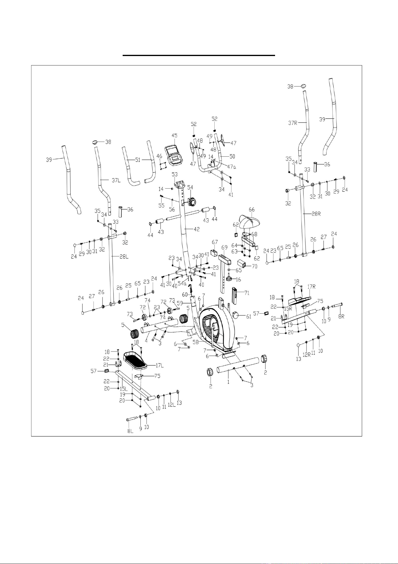
EXPLODED DIAGRAM 1
3
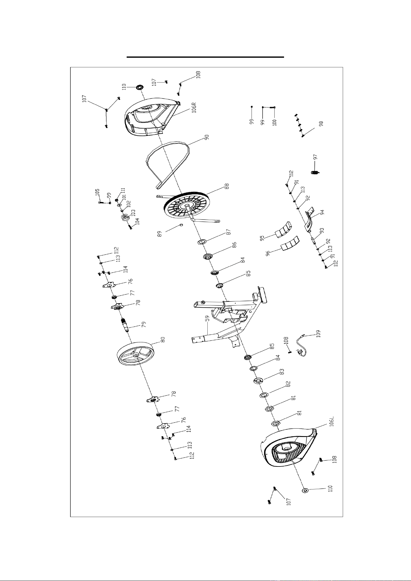
EXPLODED DIAGRAM 2

4
PARTS LIST
No.
Description
Spec.
Qty.
No.
Description
Spec.
Qty.
1
Rear Stabilizer
1
29
Hex Bolt
M8*16
2
2
Rear End Cap
2
30
Spring Washer
D8
5
3
Square Neck Bolt
M10*57
4
31
Washer
∅8.5*∅32*2
2
4
Front Stabilizer
1
32
Shaft Sleeve
∅32
4
5
Front End Cap
2
33
Hex Bolt
M8*35
2
6
Curved Washer
∅10*∅20*2
4
34
Curved Washer
∅8.5*∅20*2
11
7
Cap Nut
M10
4
35
Cap Nut
M8
2
8L
Left Crank Bolt
∅16*89
1
36
Bushing
2
8R
Right Crank Bolt
∅16*89
1
37L
Left Handlebar
1
9
Corrugated Washer
∅16*∅26*0.3
2
37R
Right Handlebar
1
10
Shaft Sleeve
∅28
4
38
Handlebar End Cap
∅28
2
11
Spring Washer
∅13
2
39
Handlebar Foam
2
12L
Left Nylon Nut
1/2"*20
1
40
Bolt
M8*62
2
12R
Right Nylon Nut
1/2"*20
1
41
Bolt
M8*20
5
13
Sphere Cap
S18
2
42
Handlebar Post
1
14
Hole Plug
2
43
Sleeve
∅19*∅32*75
2
15L
Left Connecting Rod
1
44
Corrugated Washer
∅19*∅26*0.3
2
15R
Right Connecting Rod
1
45
Computer
1
16
Adjustment Knob
M8
1
46
Cross Pan Head Screw
M5*10
4
17L/R
Left/Right Pedal
2
47
Handle Pulse
2
18
Hex Bolt
M10*45
6
47a
Handle Pulse Wire
1
19
Washer
∅10.5*∅20*2
4
48
Washer
∅6*∅12*1
2
20
Nylon Nut
M10
6
49
Screw
ST4.2*20
2
21
Connecting Plate
2
50
Small Handlebar
1
22
Washer
∅10.5*∅26*2
4
51
Handlebar Foam
2
23
Nylon Nut
M8
6
52
End Cap
2
24
Sphere Cap
S13
6
53
Trunk Wire
1
25
Sleeve
2
54
Tension Control Knob
1
26
Shaft Sleeve
∅32
4
54a
Tension Control Wire
1
27
Hex Bolt
M8*65
2
55
Screw
M5*40
1
28L
Left Swing Rod
1
56
Curved Washer
D5
1
28R
Right Swing Rod
1
57
Square End Cap
2

5
No.
Description
Spec.
Qty.
No.
Description
Spec.
Qty.
58
Crank
1
89
Magnet
1
59
Main Frame
1
90
Belt
1
60
Tension Wire
1
91
Spring Washer
D6
2
61
Pin Knob
M16
1
92
Snap Ring
D12
2
62
Square End Cap
2
93
Magnetic Board Axis
1
63
Nut
M8
3
94
Magnetic Board
1
64
Washer
∅8.5*∅19*1.5
3
95
Magnet
4
65
Washer
∅8.5*∅19*1.5
3
96
Magnetic Support
1
66
Seat
1
97
Tension Spring
1
67
Sleeve
1
98
Screw
ST3*10
5
68
Seat Slider
1
99
Nut
M6
3
69
Seat Post
1
100
Bolt
M6*60
1
70
Bushing
1
101
Washer
∅10.5*∅20*2
1
71
Bushing
1
102
Idler Sleeve
1
72
Transportation Wheel
2
103
Idler Wheel
1
73
Screw
M8*40
2
104
Bolt
M10*45
1
74
Washer
∅8.5*∅16*1.5
2
105
Bolt
M6*30
1
75
Pedal Plate
2
106L
Left Cover
1
76
Bearing Support
2
106R
Right Cover
1
77
Bearing
6001RS
2
107
Screw
ST4.2*20
6
78
Bearing Board
2
108
Screw
ST4.2*16
5
79
Flywheel Axis
1
109
Sensor
1
80
Flywheel
1
110
Hole Cap
2
81
Hex Nut
2
111
Nut
M10
1
82
Locking Washer
1
112
Bolt
M6*15
4
83
Locking Nut-Left
1
113
Washer
∅6.5*∅16*1.5
4
84
Open Face Bearing
2
114
Bolt
M6*9
6
85
Bearing Housing
2
A
Allen Wrench
S6
1
86
Locking Nut-Right
1
B
Allen Wrench
S8
1
87
Locking Washer
1
C
Spanner
S13-14-15
1
88
Belt Disk
1
D
Spanner
S17-19
1
6
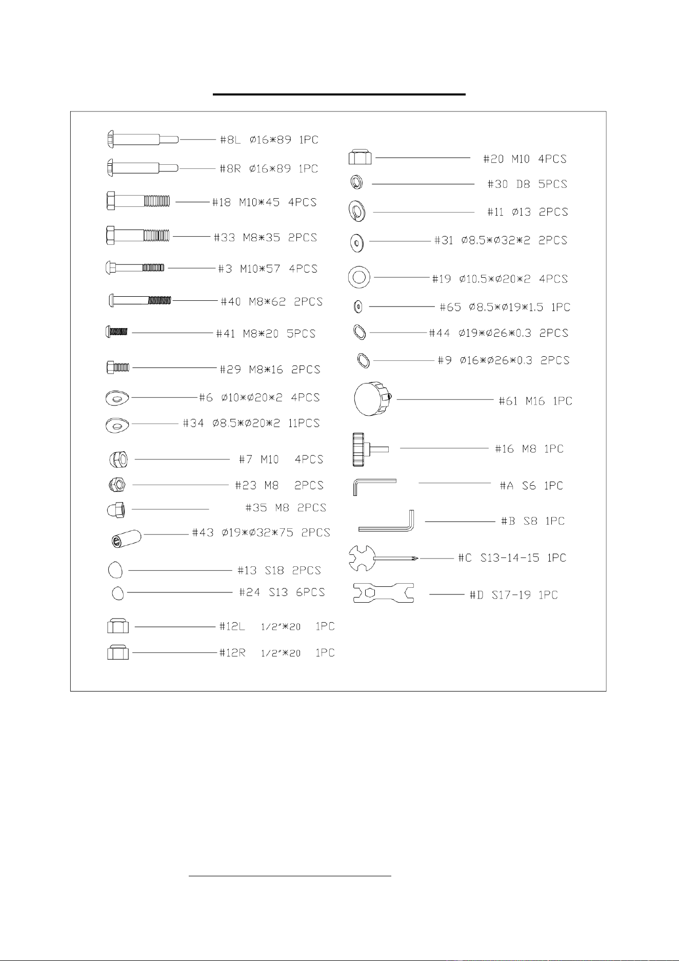
HARDWARE PACKAGE
Ordering Replacement Parts (U.S. and Canadian Customers only)
Please provide the following information in order for us to accurately identify the part(s)
needed.
The model number (found on cover of manual)
The product name (found on cover of manual)
The part number found on the “EXPLODED DIAGRAM” and “PARTS LIST” (found near
the front of the manual)
Please contact us at [email protected] or 1- 877 - 90SUNNY (877-907-8669)
7
ASSEMBLY INSTRUCTIONS
We value your experience using Sunny Health and Fitness products. For assistance with parts or
troubleshooting, please contact us at [email protected] or 1-877-90SUNNY (877-
907-8669).
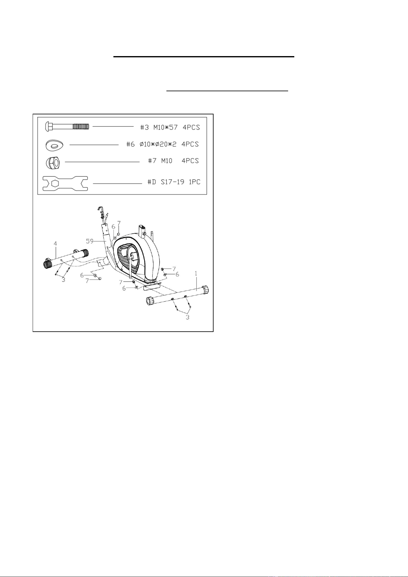
STEP 1:
Attach the Front & Rear Stabilizers (No. 4
& No. 1) to the Main Frame (No. 59) using
4 Square Neck Bolts (No. 3), 4 Curved
Washers (No. 6) and 4 Cap Nuts (No. 7).
Tighten and secure with Spanner (No. D).
8
We value your experience using Sunny Health and Fitness products. For assistance with parts or
troubleshooting, please contact us at [email protected] or 1-877-90SUNNY (877-
907-8669).
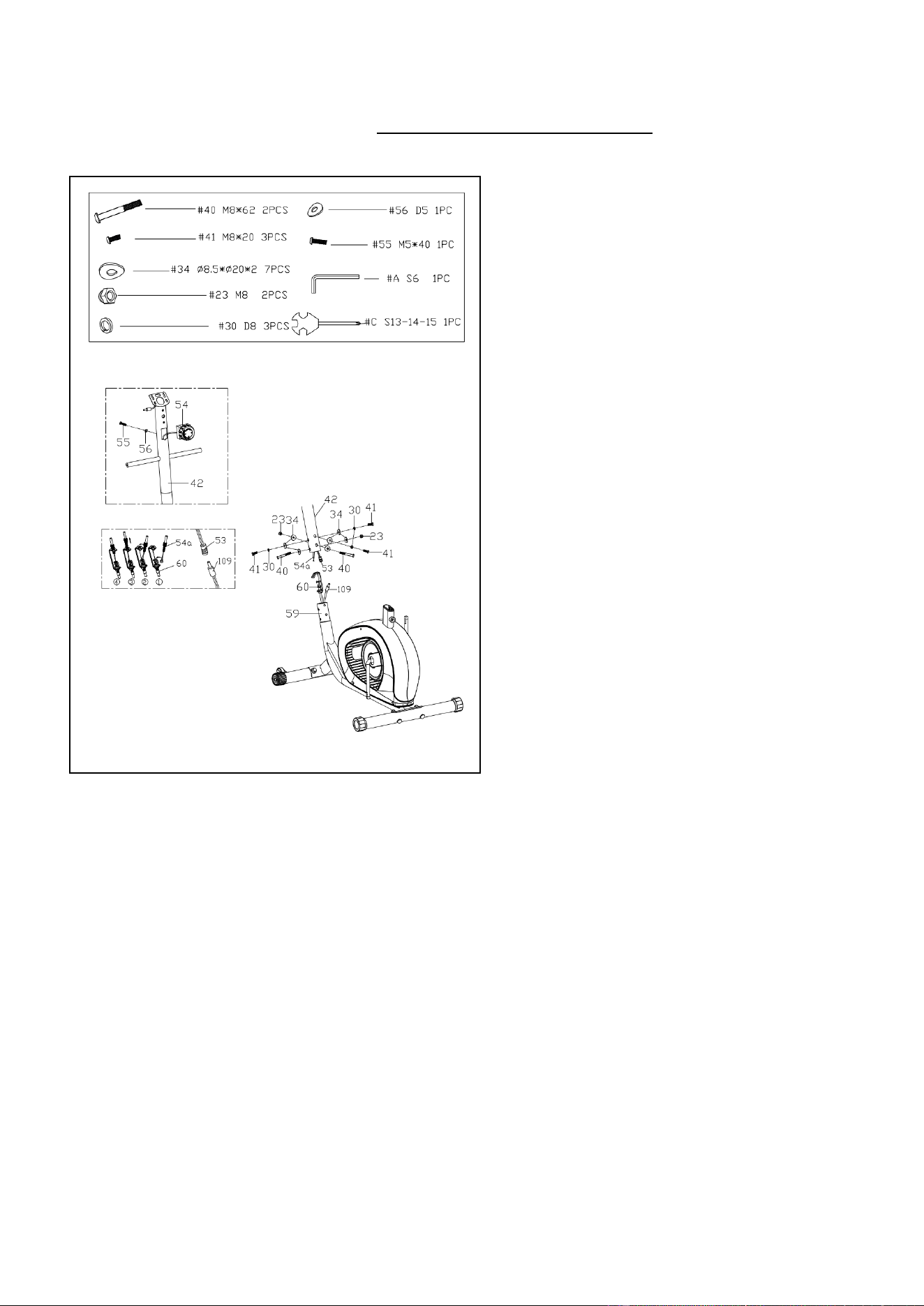
STEP 2:
Remove Screw (No. 55) and Curved
Washer (No. 56) from the Tension
Control Knob (No. 54) using Spanner
(No. C).
Insert Tension Control Wire (No. 54a)
into Handlebar Post (No. 42) and pull it
out from the bottom.
Attach the Tension Control Knob (No. 54)
to Handlebar Post (No. 42) using 1 Screw
(No. 55) and 1 Curved Washer (No. 56)
that were removed. Tighten and secure
with Spanner (No. C).
Note: Please make sure the Tension
Control Knob (No. 54) is at the lowest
resistance level (level 1, all the way to the
left) before you connect the Tension
Control Wire (No. 54a).
Connect the Trunk Wire (No. 53) with the
link wire of Sensor (No. 109) and connect
Tension Control Wire (No. 54a) with
Tension Wire (No. 60). Then, insert
Tension Control Wire (No. 54a) into the
slot on metal bracket of Tension Wire (No.
60). Make sure the metal fitting on Tension
Control Wire (No. 54a) is secured into the
metal bracket.
Attach Handlebar Post (No. 42) to the
Main Frame (No. 59) using 3 Bolts (No.
41), 2 Bolts (No. 40), 3 Spring Washers
(No. 30), 2 Nylon Nuts (No. 23) and 7
Curved Washers (No. 34). Tighten and
secure with Allen Wrench (No. A) and
Spanner (No. C).
9
We value your experience using Sunny Health and Fitness products. For assistance with parts or
troubleshooting, please contact us at [email protected] or 1-877-90SUNNY (877-
907-8669).
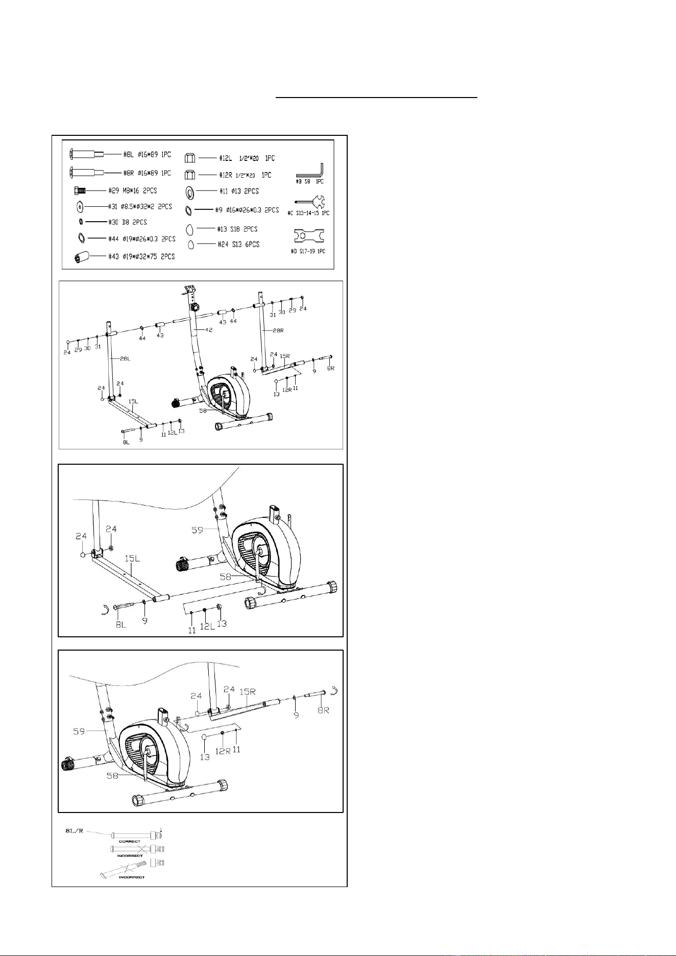
STEP 3:
Attach 2 Sleeves (No. 43) and 2
Corrugated Washers (No. 44) onto
Handlebar Post (No. 42).
Attach Left Swing Rod (No. 28L) and
Right Swing Rod (No. 28R) to Handlebar
Post (No. 42) with 2 Hex Bolts (No. 29), 2
Spring Washers (No. 30) and 2 Washers
(No. 31). Tighten and secure with Spanner
(No. C), then cover with 2 Sphere Caps
(No. 24).
Lock Left Connecting Rod (No. 15L) to the
left side of Crank (No. 58) with 1 Left
Crank Bolt (No. 8L), 1 Corrugated
Washer (No. 9), 1 Spring Washer (No. 11)
and 1 Left Nylon Nut (No. 12L). Tighten
and secure with Allen Wrench (No. B) and
Spanner (No. D). Then, cover with 2
Sphere Caps (No. 24) and 1 Sphere Cap
(No. 13). (See Fig. B)
Lock Right Connecting Rod (No. 15R) to
the right side of Crank (No. 58) with 1 Right
Crank Bolt (No. 8R), 1 Corrugated
Washer (No. 9), 1 Spring Washer (No. 11)
and 1 Right Nylon Nut (No. 12R). Tighten
and secure with Allen Wrench (No. B) and
Spanner (No. D). Then, cover with 2
Sphere Caps (No. 24) and 1 Sphere Cap
(No. 13). (See Fig. A)
NOTE: Make sure to turn Left Crank Bolt
(No. 8L) counter-clockwise, Right Crank
Bolt (No. 8R) clockwise, Left Nylon Nut
(No. 12L) clockwise, and Right Nylon Nut
(No. 12R) counter-clockwise. Failure to
follow procedures may result in permanent
damage to your elliptical bike.
Fig. B
Fig. A
10
We value your experience using Sunny Health and Fitness products. For assistance with parts or
troubleshooting, please contact us at [email protected] or 1-877-90SUNNY (877-
907-8669).
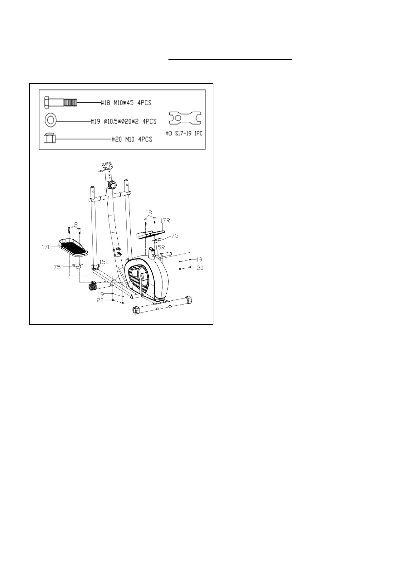
STEP 4:
Attach 2 Left & Right Pedals (No. 17L/R)
through 2 Pedal Plates (No. 75) to Left
Connecting Rod (No. 15L) and Right
Connecting Rod (No. 15R) with 4 Hex
Bolts (No. 18), 4 Washers (No. 19) and 4
Nylon Nuts (No. 20). Tighten and secure
with Spanner (No. D).
11
We value your experience using Sunny Health and Fitness products. For assistance with parts or
troubleshooting, please contact us at support@sunnyhealthfitness.com or 1-877-90SUNNY (877-
907-8669).
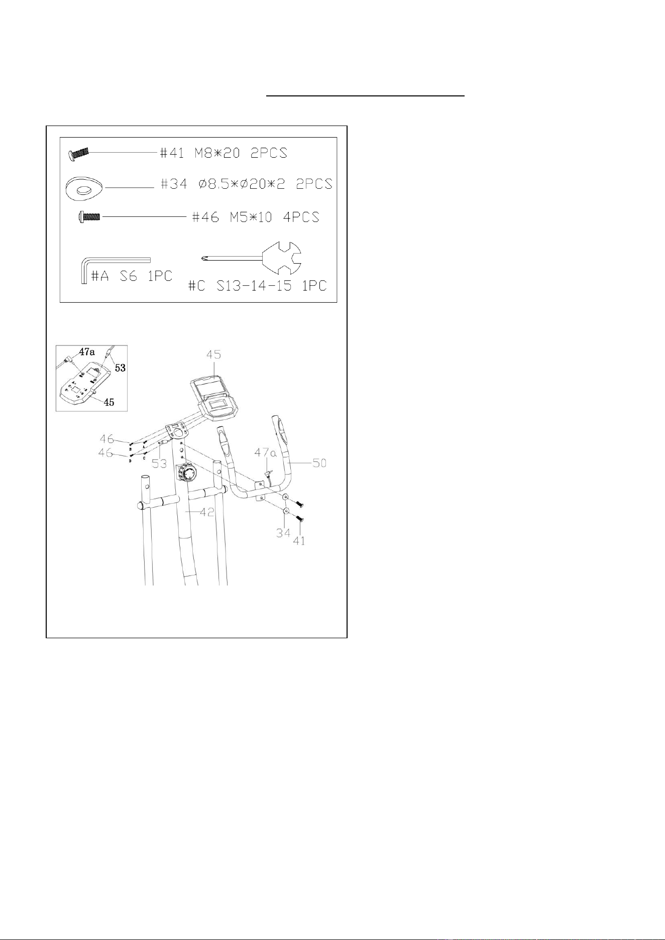
STEP 5:
Attach Small Handlebar (No. 50) to
Handlebar Post (No. 42) with 2 Bolts
(No. 41) and 2 Curved Washers (No. 34).
Tighten and secure with Allen Wrench
(No. A).
Remove the preassembled 4 Cross Pan
Head Screws (No. 46) from Computer
(No. 45) with Spanner (No. C).
Attach Computer (No. 45) to Handlebar
Post (No. 42) with 4 Cross Pan Head
Screws (No. 46) that were removed.
Tighten and secure with Spanner (No. C).
On the back of Computer (No. 45), plug
the Trunk Wire (No. 53) into the “SPEED
INPUT” jack and plug the Handle Pulse
Wire (No. 47a) into the “PULSE INPUT”
jack.
12
We value your experience using Sunny Health and Fitness products. For assistance with parts or
troubleshooting, please contact us at [email protected] or 1-877-90SUNNY (877-
907-8669).
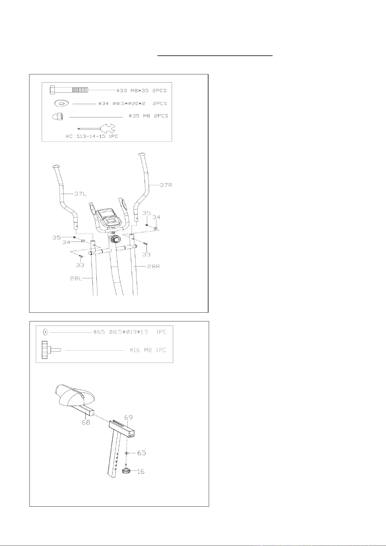
STEP 6:
Attach Left & Right Handlebars (No.
37L & No. 37R) onto Left & Right Swing
Rods (No. 28L & No. 28R) with 2 Hex
Bolts (No. 33), 2 Curved Washers (No.
34) and 2 Cap Nuts (No. 35). Tighten
and secure with Spanner (No. C).
STEP 7:
Attach Seat Slider (No. 68) onto Seat
Post (No. 69), adjust to desire position.
Tighten and secure with Washer (No. 65)
and Adjustment Knob (No. 16).
13
We value your experience using Sunny Health and Fitness products. For assistance with parts or
troubleshooting, please contact us at [email protected] or 1-877-90SUNNY (877-
907-8669).
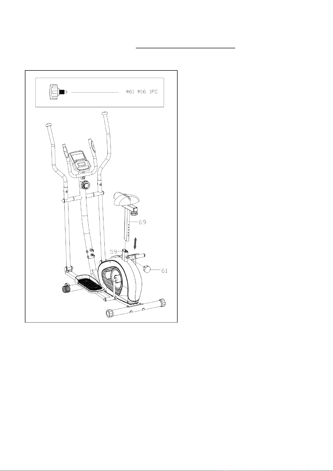
STEP 8:
Insert Seat Post (No. 69) into Main
Frame (No. 59), adjust the Seat Post
(No. 69) to desired height, then tighten
with Pin Knob (No. 61).
The assembly is complete!
14
ADJUSTMENTS & USAGE GUIDE
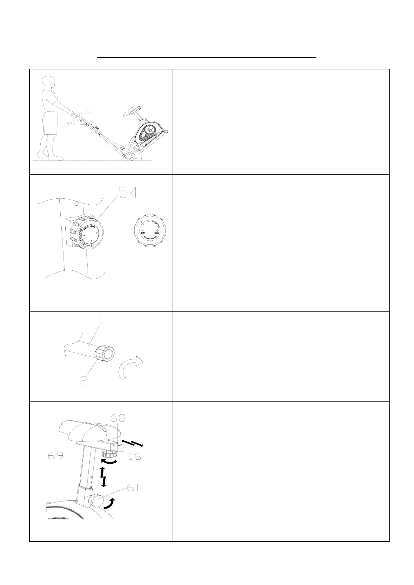
HOW TO MOVE THE ELLIPTICAL
Hold the Left & Right Handlebars (No. 37L/R) and tilt
the elliptical bike until the transportation wheels on the
Front Stabilizer (No. 4) touch the ground. Now you can
move the elliptical bike to the desired location.
ADJUSTING THE RESISTANCE
Adjust the resistance of the elliptical using the Tension
Control Knob (No. 54). Increase the level of resistance
by turning the Tension Control Knob (No. 54) to the
RIGHT (clockwise), decrease the level of resistance by
turning the Tension Control Knob (No. 54) to the LEFT
(counter-clockwise).
Tension levels are set at Level 1 being the lowest and
Level 8 being the highest.
ADJUSTING THE BALANCE
In order to achieve a smooth and comfortable ride, you
must ensure that the elliptical is stable. If you notice that
the elliptical is unbalanced during use, you should adjust
the Rear End Caps (No. 2) located beneath the Rear
Stabilizer (No. 1). To do so, turn it clockwise.
ADJUSTING THE SEAT
Loosen and pull out the Pin Knob (No. 61) to adjust the
height of the seat. You may also slide the seat forward or
backwards by loosening the Adjustment Knob (No. 16)
on the Seat Slider (No. 68). While adjusting, you will see
a limit on the Seat Post (No. 69) and Seat Slider (No.
68). Do NOT lift the posts passed these marks. Always
check the Pin Knob (No. 61) and Adjustment Knob
(No. 16) to ensure that they are fully secured when you
finish making an adjustment.
15
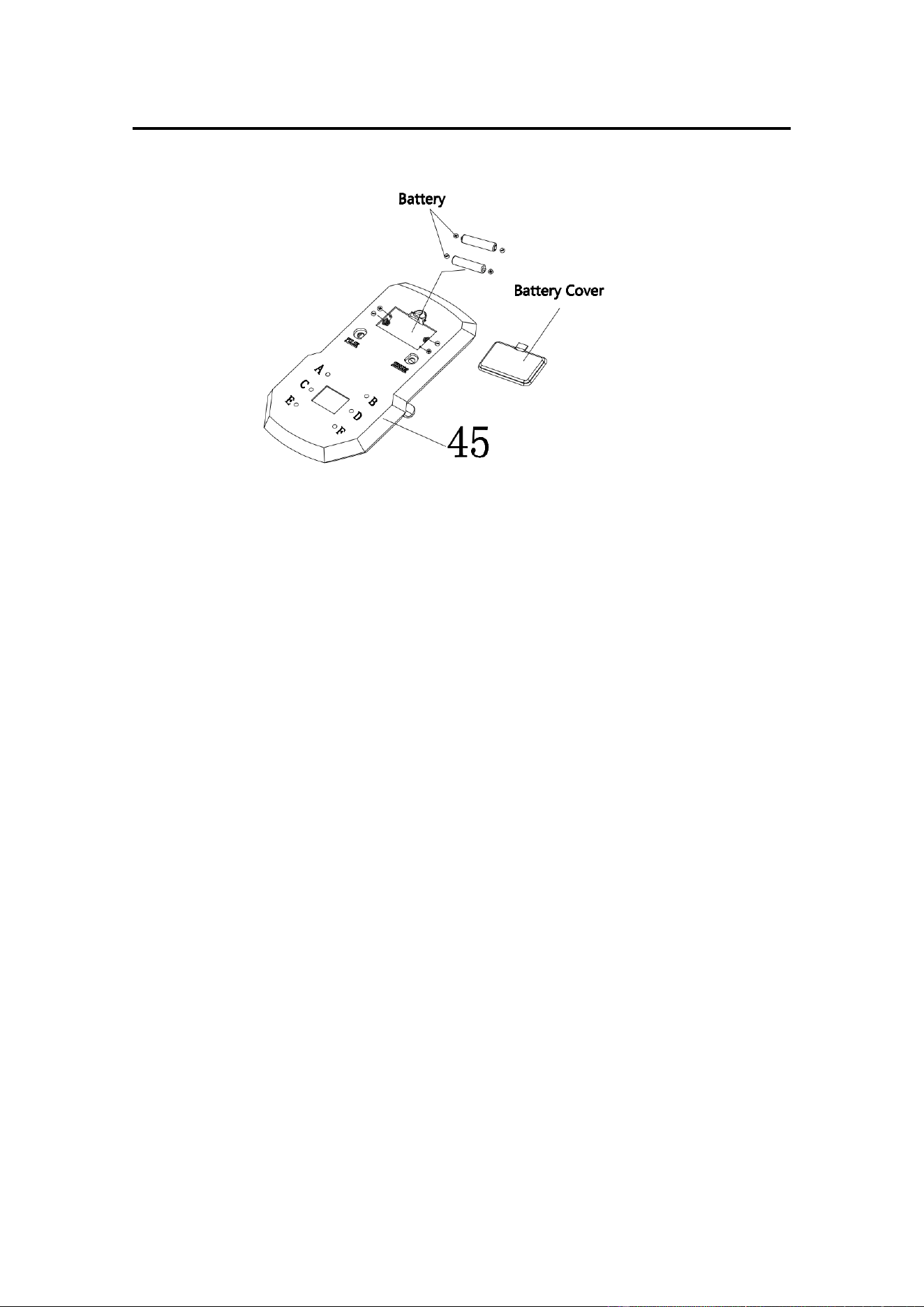
BATTERY INSTALLATION & REPLACEMENT
BATTERY INSTALLATION
1. Take out 2 AAA batteries from computer box.
2. Press the buckle of battery cover on the back of the Computer (No. 45), then remove
battery cover.
3. Install 2 AAA batteries into the battery case on the back of the Computer (No. 45). Pay
attention to the battery + and – poles before installing.
4. Press the buckle of battery cover, then put the battery cover back to the back of the
Computer (No. 45).
The installation is complete!
BATTERY REPLACEMENT
1. Press the buckle of battery cover on the back of the Computer (No. 45), then remove
battery cover.
2. Remove the 2 old AAA batteries in the battery case and install 2 new AAA batteries into
the battery case on the back of the Computer (No. 45). Pay attention to the battery + and
– poles before installing.
3. Press the buckle of battery cover, then put the battery cover back to the back of the
Computer (No. 45).
The replacement is complete!
BATTERY DISPOSAL
Dispose the batteries according to the laws and regulations of your local region. Some
batteries may be recycled. When disposing or recycling, do not mix battery types.

16
EXERCISE COMPUTER
FUNCTION BUTTONS:
MODE: Press the button to select TIME, DISTANCE, and CALORIES to preset.
Press the button for selection function display value on LCD or
enter after setting.
Press the button and hold for 3 seconds to reset all values
except odometer to zero.
(When user replaces the batteries, all the values will reset to
ZERO automatically).
SET: To set up the target value of TIME, DISTANCE, and CAL, press
the button and hold for 2 seconds to speed up the increment.
RESET: Press the button to reset function value when setting.
Press the button and hold for 3 seconds to reset all values except odometer to
zero (When the user replaces batteries, all the values will reset to ZERO
automatically).
FUNCTIONS & OPERATIONS:
1. BATTERY INSTALLATION:
Please install 2 AAA 1.5V batteries in the battery case on the back of computer.
(Whenever batteries are removed, all the function values will be reset to zero.)
2. AUTO ON/OFF:
Once the user begins to exercise, the computer will show the workout value automatically.
After about 4 minutes of inactivity, the computer will turn off. Odometer value does not
reset to 0 when the computer turns off. When the user starts to exercise again, the
workout value of odometer will accumulate continuously.
3. AUTO SCAN:
After the computer is powered on, press MODE button and the LCD will display all function
values from TIME-SPEED-DISTANCE-CALORIES-ODOMETER-PULSE. Each value will
be held for 6 seconds.
4. SPEED:
Displays the current training speed from 0.0 to 99.9 MPH (Miles per hour).
5. DISTANCE:
Accumulates total distance from 0.0 up to 9999 M (Miles). The user may preset target
distance by pressing the SET & MODE buttons. Each increment is 0.1 M (Miles).
Automatically counts down from targeting value during exercise.

17
6. TIME:
Accumulates total time from 00:00 up to 99:59. The user may preset target time by
pressing SET & MODE buttons. Each increment is 1 minute.
Automatically counts down from targeting value during exercise.
7. CALORIES:
Accumulates calories burned during training from 0 to 9999 Cal. The user may also preset
the target calories before training by pressing the SET & MODE buttons. Each setting
increment is 1 Cal.
Automatically counts down from targeting value during exercise.
Note : This data is a rough guide which cannot be used in medical treatment.
8. ODOMETER:
Displays the total accumulated distance from 0 to 9999 M (Miles). User can also press
MODE button to display the odometer value.
9. PULSE:
The computer will display the user's heart rate in beats per minute (BPM) during training.
Note : This data is a rough guide which cannot be used in medical treatment.
10. RESET:
Press the button and hold for 3 seconds to reset all values except odometer to zero.
NOTE:
1. If the computer display is abnormal, please re-install the new batteries and try again.
Always change both batteries at the same time. Do not mix battery types and do not mix
old and new batteries.
2. Battery Spec: 1.5V UM-4 or AAA (2PCS).
3. Dispose the batteries safely, according to your state and regional guidelines.

18
TROUBLESHOOTING
PROBLEM
SOLUTION
There is no display on the computer.
1. Remove the computer and verify that the wire
from the computer is properly connected to
the wire that comes from the handlebar post.
2. Check if the batteries are correctly positioned
and battery springs are in proper contact with
batteries.
3. The batteries in the computer may be
unresponsive. Change to new batteries.
The elliptical bike wobbles when in use.
Turn the rear end caps on the rear stabilizer as
needed to level the elliptical bike.
The elliptical bike makes squeaking noise
when in use.
The bolts may have become loose on the elliptical
bike. Please inspect all of the bolts and tighten
any loosened bolts.
Version 3.1

19