Loading ...
Loading ...
Loading ...
8 English
Installing the hob
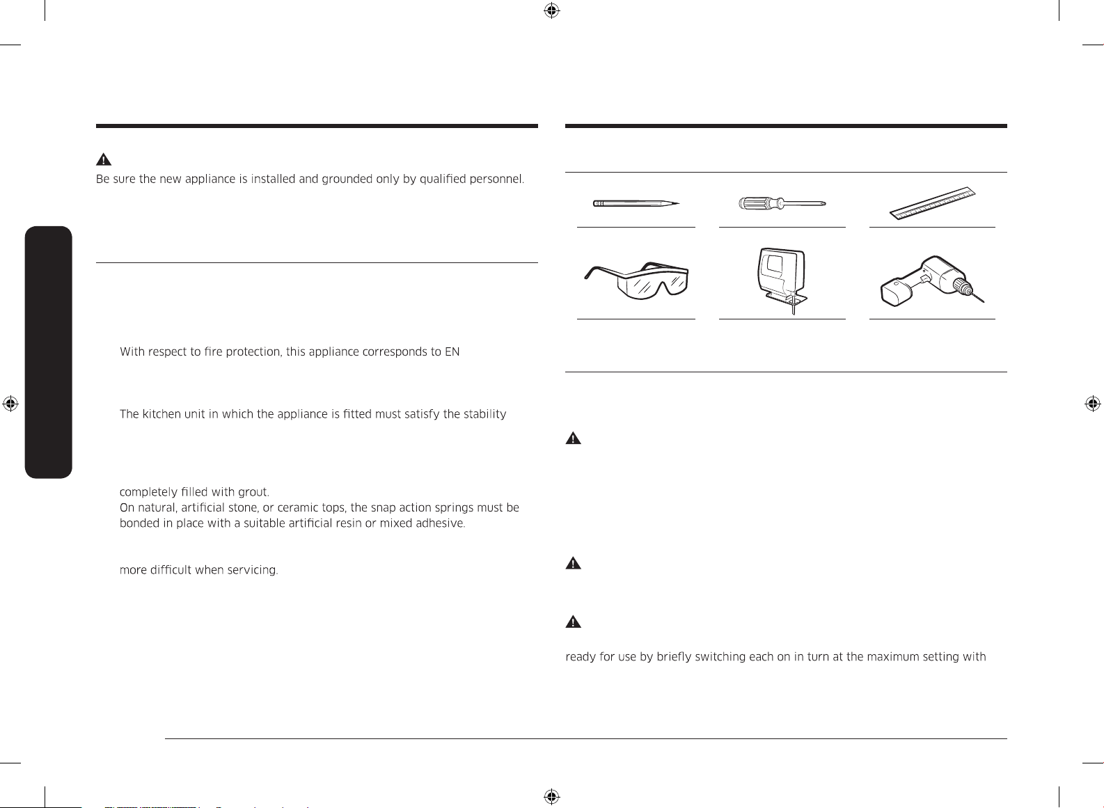
Tools you will need
Pencil Phillips Head Screwdriver Ruler or Straightedge
Safety Glasses Saber Saw Drill
Connecting to the mains power supply
Before connecting, check that the nominal voltage of the appliance, that is, the
voltage stated on the rating plate, corresponds to the available supply voltage. The
rating plate is located on the lower casing of the hob.
WARNING
Shut off power to circuit before connecting wires to circuit.
The heating element voltage is AC 230 V
~
. The appliance also works perfectly on
networks with AC 220 V
~
or AC 240 V
~
. The hob is to be connected to the mains
using a device that allows the appliance to be disconnected from the mains at all
poles with a contact opening width of at least 3 mm, eg. automatic line protecting
cut - out, earth leakage trips or fuse.
WARNING
The cable connections must be made in accordance with regulations and the
terminal screws tightened securely.
WARNING
Once the hob is connected to the mains supply, check that all cooking zones are
suitable cookware.
Installing the hob
WARNING
Please observe this instruction. The warranty will not cover any damage that may
occur as a result of improper installation.
Technical data is provided at the end of this manual.
Safety instructions for the installer
• A device must be provided in the electrical installation that allows the
appliance to be disconnected from the mains at all poles with a contact
opening width of at least 3 mm. Suitable isolation devices include line
protecting cut - outs, fuses (screw type fuses are to be removed from the
holder), earth leakage trips and contactors.
•
This type of appliance may be installed with a high cupboard or wall on one
side.
• The installation must guarantee shock protection.
•
requirements of DIN 68930.
• For protection against moisture, all cut surfaces are to be sealed with a
suitable sealant.
• On tiled work surfaces, the joints in the area where the hob sits must be
•
• Ensure that the seal is correctly seated against the work surface without any
gaps. Additional silicon sealant must not be applied; this would make removal
• The hob must be pressed out from below when removed.
• A board can be installed underneath the hob.
• The ventilation gap between the work surface and front of the unit
underneath it must not be covered.
60335-2-6.
Loading ...
Loading ...
Loading ...