

Operator's Manual
12" 24V MAX* Lithium-ion Cordless Grass Trimmer CLGT2412S
Save this manual for future reference
* Maximum initial battery workload voltage (measured without a workload) is 24 volts.
Nominal voltage is 21.6 volts.
Read all safety rules and instructions carefully before operating this tool.
Distributed By: Suzhou Cleva Electric Appliance Co., Ltd.
NO.8 Ting Rong Street 215122 Suzhou - China
Battery Model Number is 24LB2004-CN
Charger Model Number is 24LFC14-ETL

2
Section Page
TABLE OF CONTENTS
TABLE OF CONTENTS 2
SPECIFICATIONS 3
IMPORTANT SAFETY INSTRUCTIONS 4-6
SYMBOLS 7-8
KNOW YOUR GRASS TRIMMER 9-10
ASSEMBLY 11-15
BATTERY PACK AND CHARGER 16-18
OPERATION 19-25
MAINTENANCE 26-28
ENVIRONMENTALLY SAFE BATTERY DISPOSAL 29
TROUBLESHOOTING 30-31
LAWNMASTER
®
WARRANTY 32
EXPLODED VIEW 33
PARTS LIST 34
NOTES 35-36

3
SPECIFICATIONS
Type Cordless, Battery-powered
No-load Speed 8200 RPM
Line Diameter 0.065" (1.6 mm)
Cutting Width 12" (300 mm)
Unit Weight (With 2.0Ah Battery) 5.73 lbs (2.6 kg)
24V MAX* CORDLESS GRASS TRIMMER
Model Number 24LB2004-CN
Rated Voltage of Battery 24 V Max* D.C
Capacity of Battery 2.0 Ah
Battery Type Lithium-ion
BATTERY PACK
Model Number 24LFC14-ETL
Charger Input 120 V ~ 60 Hz 70 W
Charger Output 24 V D.C. 2.5 A
Charging Time 60 minutes (For 24LB2004-CN)
* Maximum initial battery workload voltage (measured without a workload) is 24 volts.
Nominal voltage is 21.6 volts.
BATTERY CHARGER
4
IMPORTANT SAFETY INSTRUCTIONS
Read and understand all instructions before using this product.
injury.
WARNING
rubber gloves and substantial footwear is recommended when working outdoors. Wear protective
hair covering to contain long hair.
which it was designed.
tired.
when changing accessories such as cutting line, and so on.
locked-up place, out of reach of children.
the risk of injury. Follow instructions for lubricating and changing accessories. Inspect the cord
periodically, and if damaged, have it repaired by an authorized service center. Inspect extension
cords periodically and replace if damaged. Keep handles dry, clean, and free from oil and grease.
should be carefully checked to determine that it will operate properly and perform its intended
function. Check for alignment of moving parts, binding of moving parts, breakage of parts, mounting,
and any other condition that may affect its operation. A guard or other part that is damaged should
be properly repaired or replaced by an authorized service center unless indicated elsewhere in this
manual.
the tool that has the switch on, invites accidents.
gases, or dust. Power tools create sparks which may ignite the dust or fumes.
5
IMPORTANT SAFETY INSTRUCTIONS
proper instruction.
switch is dangerous and must be repaired.
or line which can be thrown or become entangled in the tool.
BATTERY PACK
ETL chargers.
pack.
shock.
explosion and possibly injury.
eyes or skin. It may be toxic if swallowed.
from the battery may cause irritation or burns.
dropped or received a sharp blow. A damaged battery is subject to explosion. Properly dispose of a
dropped or damaged battery immediately.
them with clean water for at least 10 minutes, then seek immediate medical attention. Following this
rule will reduce the risk of serious personal injury.
keys, nails, screws, or other small metal objects, that can make a connection from one terminal to
temperature above 265°F (130°C) may cause an explosion.
indicated in the instructions for use and care.
6
IMPORTANT SAFETY INSTRUCTIONS
parts. This will ensure that the safety of the product is maintained.
BATTERY CHARGER
CN, 24LB2605, or 24LB4005 lithium-ion batteries.
of batteries may burst, causing personal injury or damage.
If damaged, immediately discontinue use. Replace the charger with the identical unit as listed in the
Parts List of this manual.
the risk of electric shock. If the charger cord is damaged, replace the charger with an identical
model as listed in this manual.
another battery pack.
FCC COMPLIANCE
conditions:
- This device may not cause harmful interference, and
- This device must accept any interference received, including interference that may cause
undesired operation.
NOTE:
device, pursuant to Part 15 of the FCC Rules. These limits are designed to provide reasonable
protection against harmful interference in a residential installation.
used in accordance with the instructions, may cause harmful interference to radio communications.
However, there is no guarantee that interference will not occur in a particular installation. If
interference by one or more of the following measures:
- Reorient or relocate the receiving antenna.
SAVE THESE INSTRUCTIONS
someone this appliance, loan them these instructions also.
7
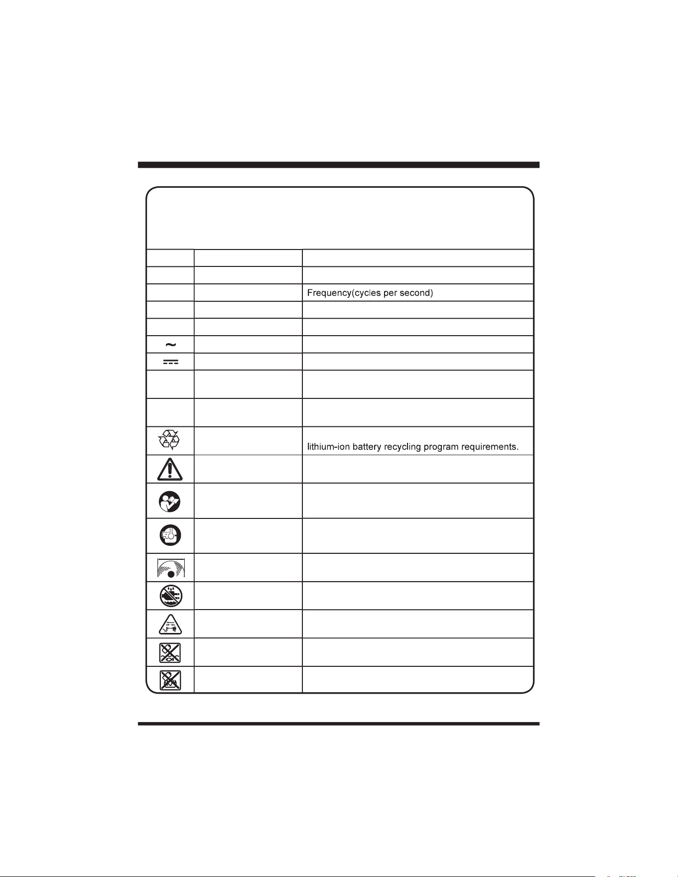
SYMBOLS
SYMBOL NAME DESIGNATION/EXPLANATION
V Volts Voltage
A Amperes Current
Hz Hertz
W Watts Power
hrs Hours Time
Alternating Current Type of current
Direct Current Type or a characteristic of current.
…/min Per Minute
Revolutions, strokes, surface speed, orbits, etc., per
minute.
n
0
No Load Speed Rotational speed, at no load.
Lithium-ion Battery
Recycling
Designates that this tool is in compliance with
Safety Alert Precautions that involve your safety.
Read the Operator’s
Manual
To reduce the risk of injury, user must read and
understand Operator’s Manual before using this
product.
Eye and Hearing
Protection
Always wear eye protection with side shields marked
to comply with ANSI Z87.1, along with hearing
protection.
Cutting Width Cutting diameter.
Wet Conditions Alert Do not expose to rain or use in damp locations.
Keep Bystanders Away Keep all bystanders at least 50 ft. away.
Keep Away From Water
Do not dispose of battery packs in rivers or immerse
in water.
Keep Away From Fire
Do not dispose of battery packs in explode or leak
and cause injury.
Some of the following symbols may be used on this product. Please study them and
learn their meaning. Proper interpretation of these symbols will allow you to operate
the product better and safer.
8
SYMBOL SIGNAL MEANING
DANGER
Indicates an imminently hazardous situation, which, if not
avoided, will result in death or serious injury.
WARNING
Indicates a potentially hazardous situation, which, if not
avoided, could result in death or serious injury.
CAUTION
Indicates a potentially hazardous situation, which, if not
avoided, may result in minor or moderate injury.
NOTICE
(Without Safety Alert Symbol) Indicates a situation that may
result in property damage.
The following signal words and meanings are intended to explain the levels of risk
associated with this product.
SERVICE
technician. When servicing, use only identical replacement parts.
For troubleshooting or replacement, please call Customer Service for assistance (Toll free number
866-384-8432).
To avoid serious personal injury, do not attempt to use this product until you read thoroughly and
understand completely the Operator’s Manual.
If you do not understand the warnings and instructions in the Operator’s Manual, do not use this
product. Call Customer Service for assistance (Toll free number 866-384-8432).
WARNING
SYMBOLS
SYMBOL NAME DESIGNATION/EXPLANATION
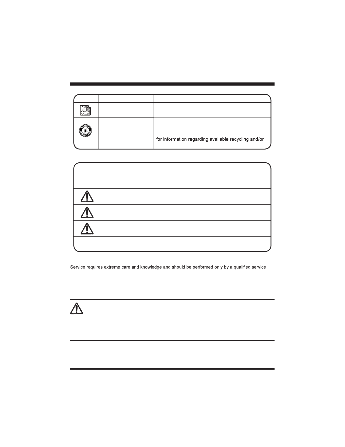
Heat Alert
Do not expose battery packs to heat in excess of
60ºC (140ºF).
Recycle Symbol
This product uses lithium-ion batteries. Local, state
or federal laws may prohibit disposal of batteries in
ordinary trash. Consult your local waste authority
disposal options.
9
KNOW YOUR GRASS TRIMMER
8
14
19
17
20
3
4
5
6
7
1
2
9
10
11
12
13
15
16
18
21

10
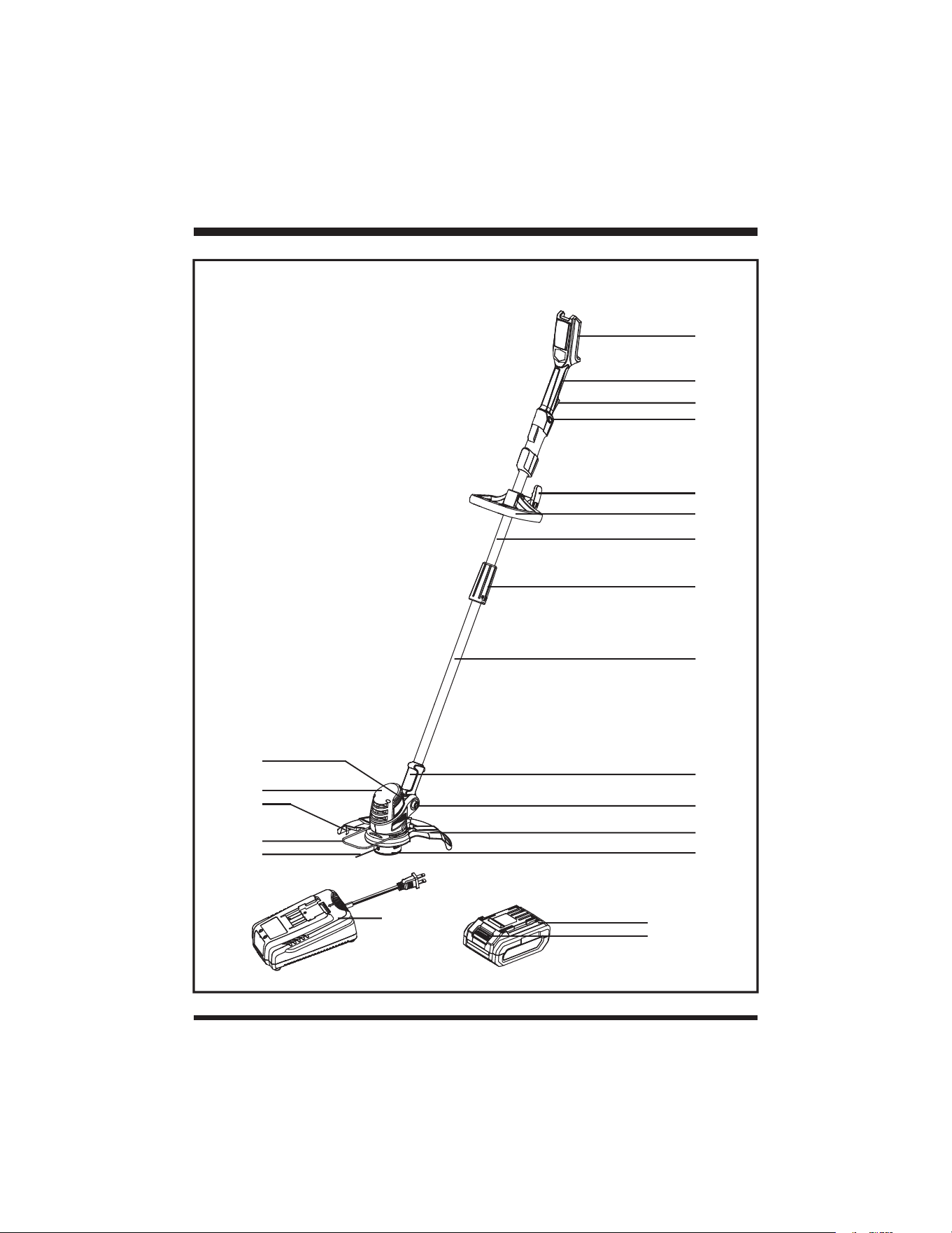
KNOW YOUR GRASS TRIMMER
Components
1.Battery Housing
2. Main Handle
4. Lock-off Switch
5. Auxiliary Handle
Locking Knob
6. Auxiliary Handle
7. Upper Shaft
8. Locking Collar
9. Lower Shaft
10. Shaft Collar Support
11. Pivot Button
12. Debris Guard
13. Trimmer Head
14. Trimming Line
15. Flower Guard
16. Trimming Line Cut-off Blade
17. Motor Housing
18. Air Vents
19. Battery Charger
20. Battery Pack
21. Battery Release Button
KNOW YOUR PRODUCT
Manual as well as a knowledge of the project you are attempting. Before use of this product, familiarize
yourself with all operating features and safety rules.

11
Before assembly, make sure that the grass trimmer is switched off and the battery is removed. If any
parts are damaged or missing, do not operate this product until the parts are replaced. Failure to heed
this warning so could result in serious personal injury.
Do not attempt to modify this product or create accessories not recommended for use with this
product.
possible serious personal injury. Always remove battery pack from your tool when you are assembling
parts, making adjustments, cleaning, or when not in use. Removing battery pack will prevent accidental
starting that could cause serious personal injury.
Never operate without the proper safety devices in place and working. Never operate with damaged
safety devices. Failure to heed this warning can result in serious personal injury.
ASSEMBLY
UNPACKING
Carefully remove the product and any accessories from the box. Make sure that all items listed in
the packing list are included.
Inspect the product carefully to make sure no breakage or damage occurred during shipping.
Do not discard the packing material until you have carefully inspected and satisfactorily operated
the product.
If any parts are damaged or missing, please call Customer Service (Toll free number 866-384-
8432).
YOU WILL NEED (ITEMS NOT SUPPLIED)
PACKING LIST
(1) Main Handle
(1) Lower Shaft (with trimmer head and line spool installed)
(1) Debris Guard
(1) Flower Guard
(1) Auxiliary Handle (with auxiliary handle locking knob installed)
(1) Operator's Manual
(1) 24V 2.0Ah Lithium-ion Battery Pack
(1) 24V 2.5A Battery Charger
WARNING
12
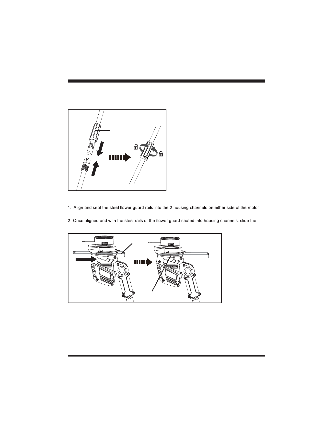
CONNECTING THE MAIN HANDLE AND SHAFT
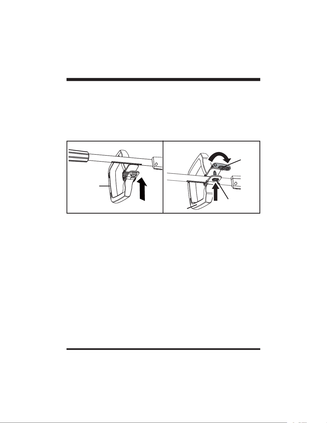
1. Align the upper shaft with the lower shaft. The triangle-shaped recesses must face each other.
2. Insert the upper shaft into the lower shaft and fasten both shafts with the locking collar (Fig. 1).
ATTACHING THE FLOWER GUARD
housing (Fig. 2).
guard forward until the closed end of the guard is against the motor housing (Fig. 2).
ASSEMBLY
Fig. 1
Locking Collar
Fig. 2
Steel Rails
Housing Channel
13
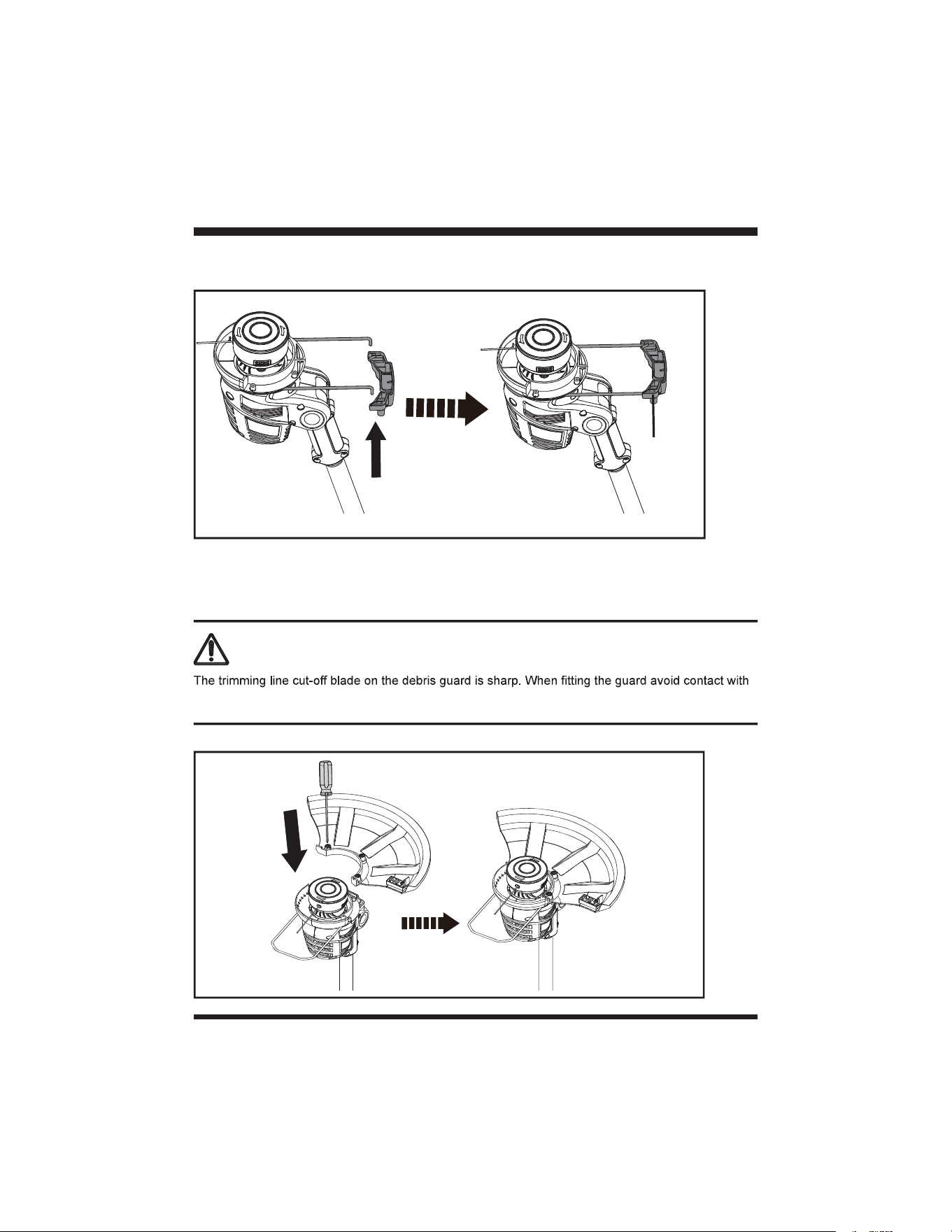
3. With the two steel rails exposed, align the two holes in the plastic toe pad with the end of the steel
rails of the guard and snap into place securely (Fig. 3).
ASSEMBLY
FITTING THE DEBRIS GUARD
1. Align the debris guard with the trimmer head.
2. Secure the debris guard by tightening the 3 mounting screws with a screwdriver (Fig. 4).
the blade. Failure to avoid contact can result in serious personal injury.
WARNING
Fig. 4
Fig. 3
Plastic Toe
Pad
14
ASSEMBLY
ATTACHING THE AUXILIARY HANDLE
1. Loosen the auxiliary handle locking knob and remove it from the auxiliary handle.
2. Align the auxiliary handle with the upper shaft (Fig. 5).
3. Adjust the auxiliary handle to the most comfortable position.
4. Insert the bolt in the hole on the auxiliary handle, tighten the locking knob and clamp down to secure
the handle (Fig. 6).
NOTE: Auxiliary handle can be mounted from either side of the shaft to accommodate personal
preference of use.
Auxiliary Handle
1
2
Fig. 5 Fig. 6
Bolt
Locking Knob
15
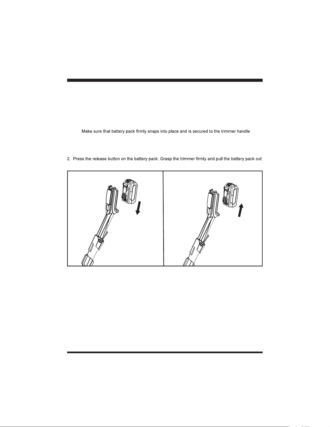
INSTALLING / REMOVING THE BATTERY PACK
To install the battery pack:
1. Make sure the battery is fully charged.
2. Align the battery pack with the battery slot on the underside of the main handle, and then insert the
battery pack into the handle (Fig. 7).
3. Push the battery pack until you hear a “click”.
NOTE:
before starting operation.
To remove the battery pack:
1. Stop the grass trimmer.
of the main handle (Fig. 8).
ASSEMBLY
Fig. 7 Fig. 8
16
BATTERY PACK AND CHARGER
BATTERY CHARGING
1. Use only with 24V LawnMaster
®
designed for the lithium-ion battery used in this tool.
2. Check the power voltage! Battery chargers operate on 120V.
3. The battery is charged between 40°F (4°C) and 100°F (38°C). This ensures an optimum battery
service life.
4. Protect the battery from heat, from continuous exposure to sun, and keep away from radiation or
other heat sources. Do not leave the battery in the tool in direct sunlight over long periods.
5. The battery is supplied partially charged. To ensure full capacity of the battery, charge the battery
reducing its service life. Interrupting the charging procedure does not affect the battery.
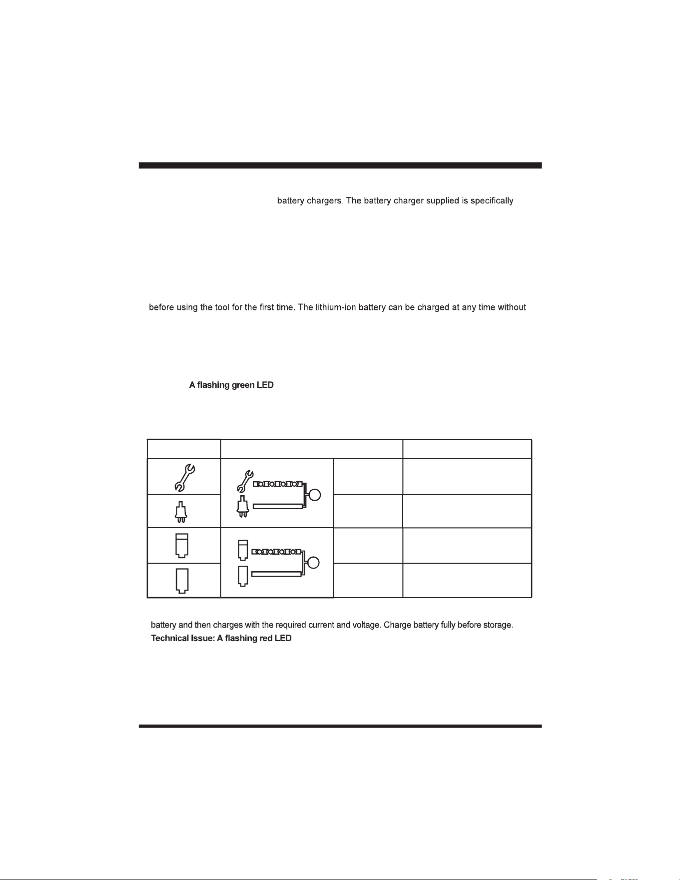
LED CHARGER STATUS
1. If the battery is not inserted into the charger, a continuous red LED light indicates that the charger is
plugged into a power supply socket and is now ready to begin charging.
2. Charging: on the charger indicates that the battery is charging normally.
3. Charged: Continuous green LED on the charger indicates that the battery is ready for use.
The indicator lights on the charger show the charger status:
4. The intelligent charger ensures maximum battery life, because it measures the existing charge level of the
5. light on the charger indicates that battery pack has a charging
problem or might be defective.
a) One possible condition is the battery temperature is not within the charging temperature range of 40°F
(4°C) and 100°F (38°C). As soon as the permitted temperature is reached, the battery charger will
automatically switch to charging.
SYMBOL INDICATOR LIGHTS STATUS
Red, blinking
Charging paused. See
Technical Issue.
Red, continuous Connected to power supply.
Green, blinking Charging.
Green,
continuous
Fully charged.
17
BATTERY PACK AND CHARGER
the battery pack. If the LED status repeats a second time, try to charge another identical battery. If
the battery charges normally, dispose of the defective battery pack (see Environmental Safe Battery
Disposal section).
normal), the charger may be defective. Replace with a new one.
6. After continuous or repeated charging cycles without interruption, the charger may warm up. This is normal
and does not indicate a technical defect of the battery charger.
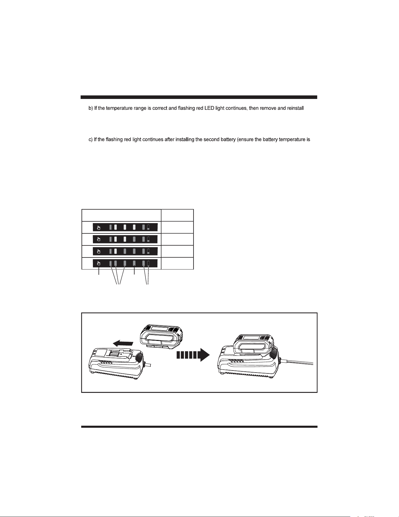
BATTERY LED PANEL
1. Check the battery pack capacity by pressing the LED button.
2. When the LED button is pressed, the number of illuminated lights indicates the state of battery pack
capacity. See Table below.
CHARGING THE BATTERY PACK
Fig. 9
NUMBER of LIGHTED LEDs CAPACITY
0%-25%
25%-50%
50%-75%
75%-100%
LED
Button
green
yellow
red
18
BATTERY PACK AND CHARGER
1. Align the slot of the battery pack with the rail on the charger. Slide the battery onto the rail until the
battery pack secures into place (Fig. 9).
2. Connect the charger to the power supply.
supply.
4. Press the release button on the battery pack and remove it from the charger.
NOTE: It is normal for the battery pack and the charger to become warm (but not hot) during charging
process. If the battery does not charge properly, check to make sure the electrical outlet is operational.
Always charge the battery before storage!
WARNING
If any part of the charger is missing or damaged, do not operate it! Replace the charger with a new
one. Failure to heed this warning could result in possible serious injury.
Check the voltage! The voltage must comply with the information on the rating label.
19
OPERATION
INTENDED USE
This trimmer is intended for cutting weed, grass or similar soft vegetation in areas that are hard to
reach, e.g. under bushes, on slopes and edges. It must not be used to work on unusual thick, dry or
wet grass, e.g. pasture grass, or to shred leaves.
This product is intended for private domestic use only, not for any commercial trade use. It must not be
used for any purposes other than those described.
SWITCHING ON/OFF
1. Make sure that the battery pack is installed properly.
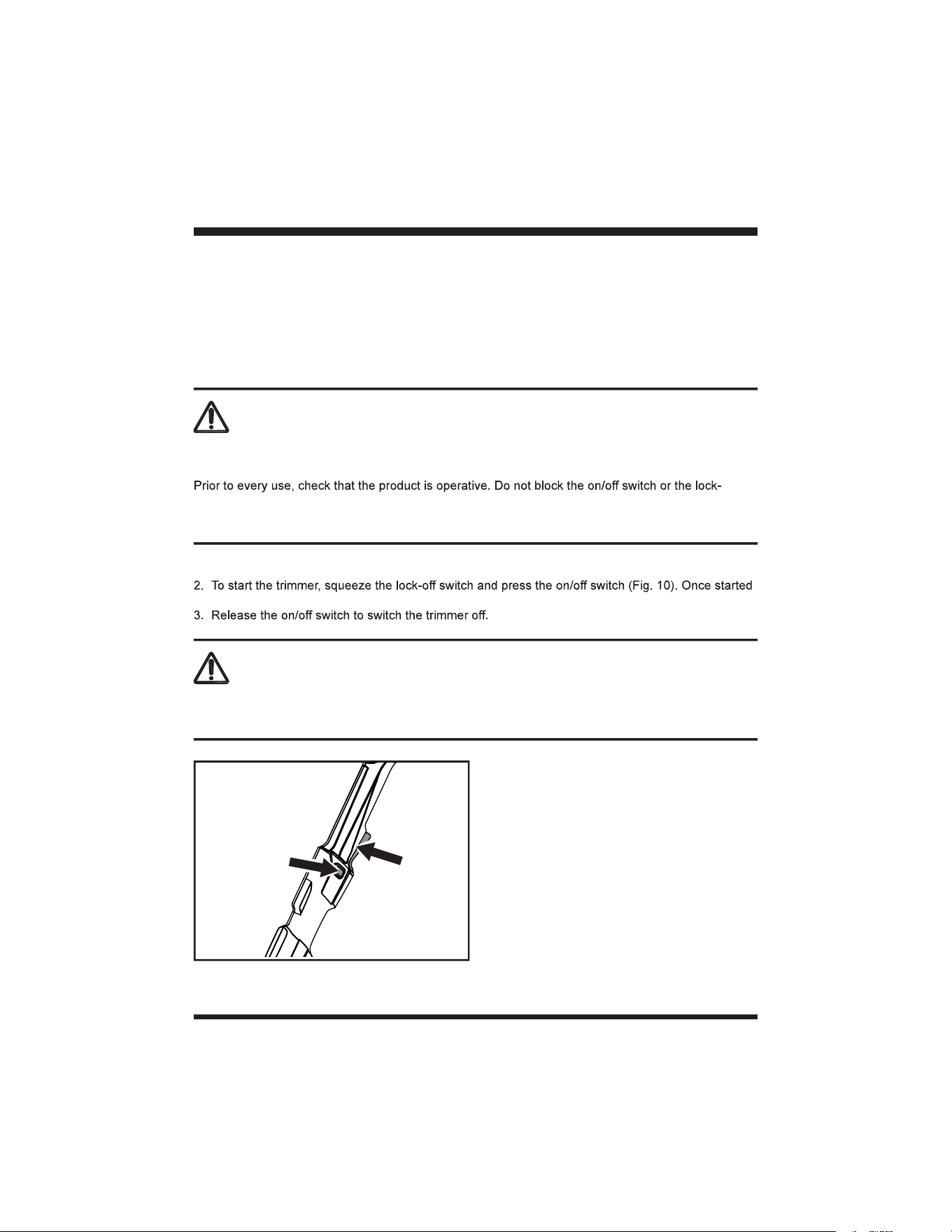
release the lock-off switch.
Fig. 10
1
2
Risk of injury! Do not operate the product without the debris guard.
To operate the product, wear suitable clothing, eye and ear protection.
off switch. The switches must reliably turn off the motor when you release them. Do not operate the
product if one of the switches is damaged.
WARNING
After turning off the trimmer, the trimmer head will continue to rotate for some time. Allow the trimmer
head to come to a complete standstill. Keep hands and feet well away. Risk of injury!
WARNING
20
OPERATION
When no line end is visible:
Replace the line spool (see Spool Replacement instructions in the Maintenance section).
DEBRIS GUARD
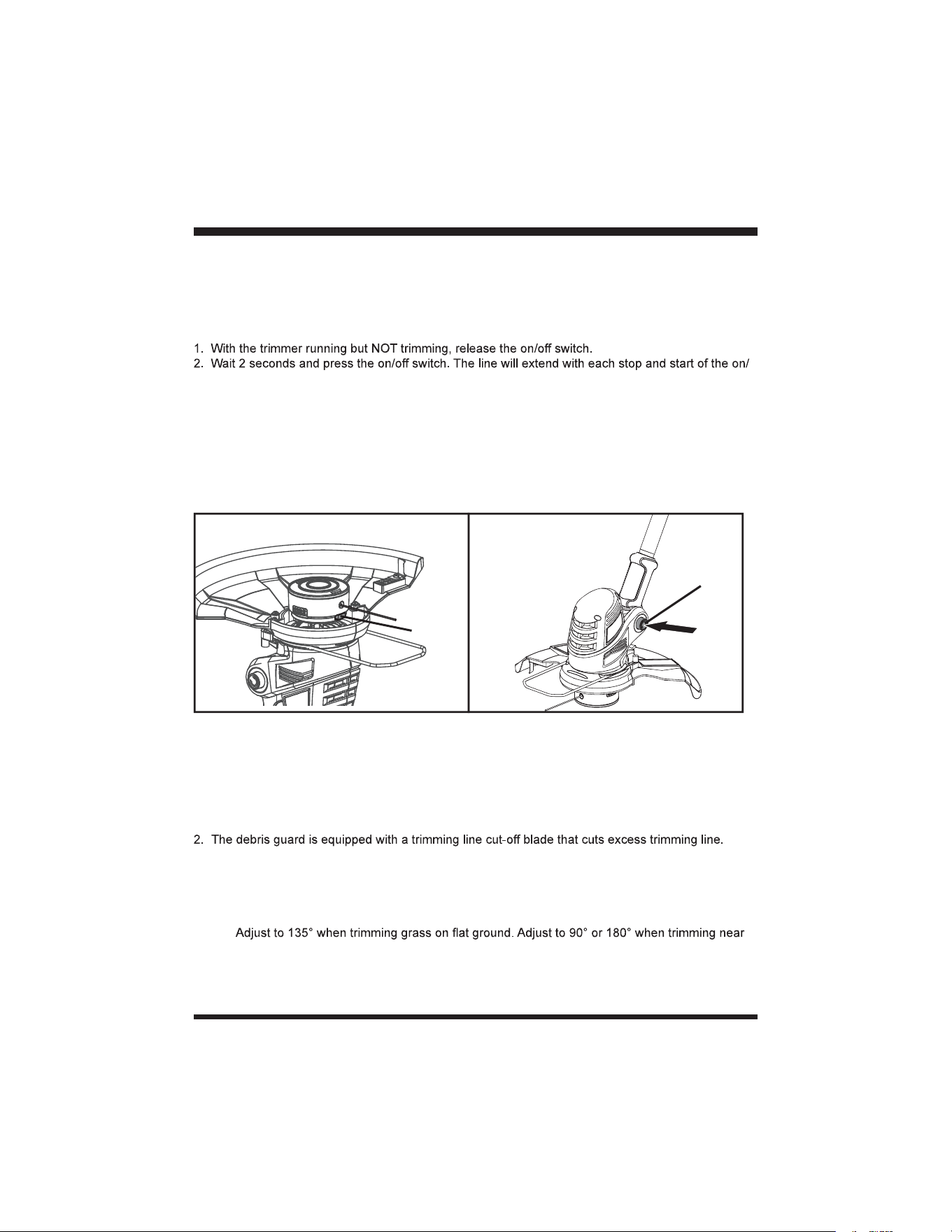
1. The debris guard protects the operator against thrown objects during operation.
PIVOTING HEAD
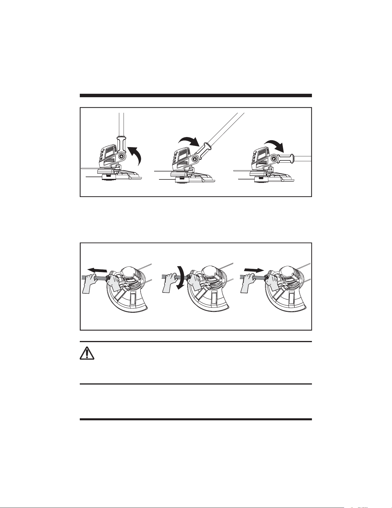
1. To pivot the head, push the pivot button and adjust the shaft to any of the 7 positions (Fig. 12).
2. Adjust the angle of the trimmer head according to the intended operation (Fig. 13).
NOTE:
edges and walls.
3. Release the button, make sure the shaft locks into place.
Fig. 11
Advance
Button
Fig. 12
Pivot Button
ADVANCING THE TRIMMING LINE
The trimmer features a fully automatic single line system. The line will automatically elongate every
time you turn on the trimmer.
NOTE: Bumping the head to try to advance the line will damage the trimmer and void the warranty.
off switch until the line reaches the length of the trimming line cut-off blade.
3. Resume trimming.
Adjusting the line length manually:
1. Switch off the trimmer and remove the battery.
2. Push the advance button located on the trimmer head while pulling on trimming line to manually
advance the line. The line will advance and stop. Push the button again to advance more line
(Fig. 11).
3. Push the button and pull the line out as many times as it takes to reach the line cut-off blade.
21
OPERATION
EDGING
The trimmer head can be rotated on the lower shaft into a position for edging sidewalks and walkways.
Pull the lower shaft outwards and away from the trimmer head as shown. Rotate the lower shaft
180° and push shaft back toward the trimmer head (Fig. 14). Shaft will lock into place for the edging
position.
Fig. 13
90°
180°
1
135°
Fig. 14
2 3
WARNING
Always ensure that the trimmer head engages into place! Only adjust to indicated angles. Never adjust
to any other intermediate position!
22
OPERATION
GENERAL OPERATION
1. Check the product, its battery pack, and charger as well as accessories for damage before each
use. Do not use the product if it is damaged or shows wear.
you keep your balance with your feet apart.
4. Ensure that the air vents are always unobstructed and clear. Clean them if necessary with a soft
brush. Blocked air vents may lead to overheating and damage the product.
5. Switch the product off immediately if someone enters the work area. Always let the product come to
a complete stop before putting it down.
6. Do not overwork yourself. Take regular breaks to ensure you can concentrate on the work and have
full control over the product.
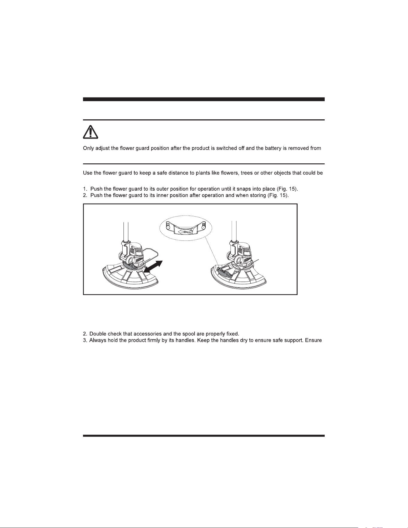
Fig. 15
Outer Position Inner Position
FLOWER GUARD
hit by the cutting device.
WARNING
the trimmer. Ensure that the trimmer head is at a complete stop.
23
WARNING
Ensure the protective tape on the trimming line cut-off blade is removed before use and the debris
OPERATION
Fig. 16
TRIMMING
WARNING
Always hold the trimmer away from the body keeping clearance between the body and the trimmer.
Any contact with the trimmer head while operating can result in serious personal injury.
1. Do not cut wet grass because it tends to stick to the trimmer head and guard, preventing proper
discharge of grass clippings, and could cause you to slip and fall.
2. Wait until the product has come to a standstill before placing it down.
3. Regularly remove clippings and dirt around the trimmer head with the battery removed from the
product.
4. Pay attention when operating the tool close to trees and bushes. The cutting device can damage
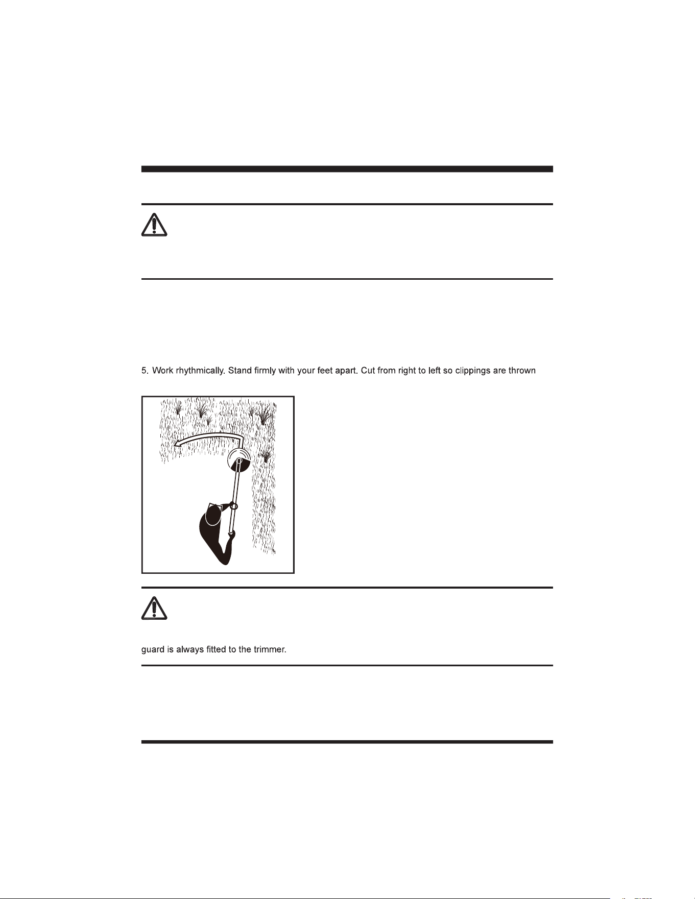
softer bark and fence posts.
away from the trimmer head (Fig. 16).
24
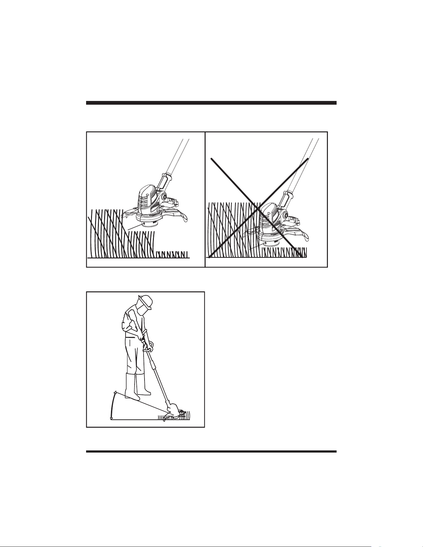
8. Keep the trimmer head at an angle of about 30° to the ground when trimming. Avoid pressing it
against the ground as this can ruin the lawn and damage the product (Fig. 19).
OPERATION
30°
Fig. 19
6. Do not move the product too fast as this will result in ineffective cutting and possible damage.
7. Cut in layers if the grass is tall, starting with the top layers and then the bottom (Fig. 17 & 18).
Fig. 17 Fig. 18
NOTE: Let the cutting device do the work. Let it work at its own pace, never force it into the
area to be cut.
25
Fig. 20 Fig. 21
OPERATION
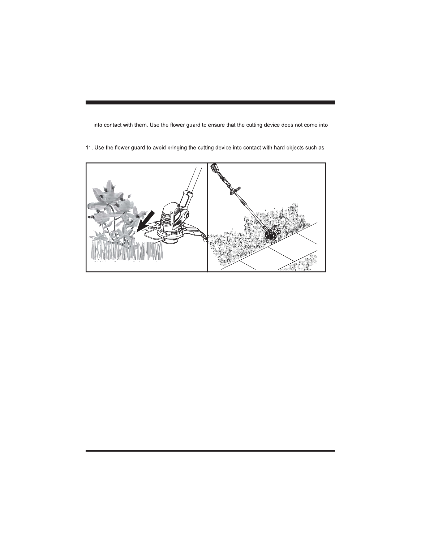
9. Carefully manoeuvre the tool around objects, such as trees and bushes, ensuring it does not come
contact with fragile plants (Fig. 20).
10. Adjust the trimmer head angle when trimming on edges and near walls.
walls and curbs (Fig. 21).
AFTER USE
1. Switch the product off, remove the battery pack and let it cool down.
2. Check, clean and store the product as described below.
26
MAINTENANCE
CLEANING
1. Clean the product with a dry cloth. Use a brush for areas that hard to reach.
2. In particular clean the air vents after every use with a cloth and brush. Keep the air vents free of
obstructions, sawdust, and wood chips. Do not spray, wash, or immerse the air vents in water.
3. Remove stubborn dust with high pressure air (max. 3 bar).
NOTE: Do not use chemical, alkaline, abrasive or other aggressive detergents or disinfectants
to clean this product as they might be harmful to its surfaces.
4. Check for worn or damaged parts. Replace worn parts as necessary or contact an authorized
service center for repair before using the product again.
5. Keep the safety guard clean and free of debris. Remove trimmings. Replace the guard with a one
of the same type when it’s worn or shows damage
WARNING
adjusting, inspecting, or cleaning the grass trimmer.
WARNING
Always remove the battery prior to replacing the line spool. Failure to do so, can cause serious injury!
The trimming line cut-off blade, located on the debris guard is sharp. Take extra care and wear
protective gloves.
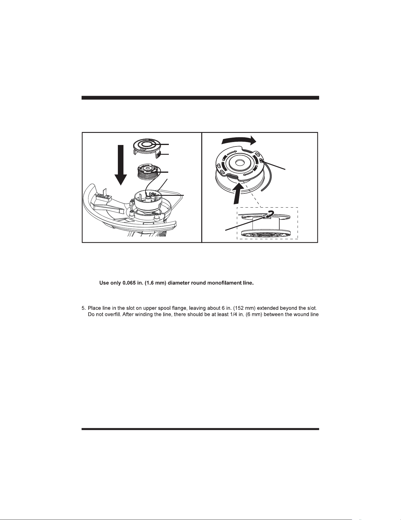
SPOOL REPLACEMENT (FIG. 22)
replacement line for best performance.
2. Remove the battery pack.
3. Push in tabs on both sides of the spool cover.
4. Pull the spool cover up to remove.
5. Remove the spool.
NOTE: Always clean the spool cover and spool base before reassembling the trimmer head.
6. Check the spool cover, spool, and spool base for wear. If necessary, replace the worn parts.
7. To install the new spool, make sure the line is captured in the spool slot on the new spool. Make
sure the end of the line is extended approximately 6 in. (152 mm) beyond the slot (Fig. 23).
8. Install the new spool so that the line and slot are aligned with the eyelet in the line head. Thread the
line into the eyelet.
9. Pull the line extending from the eyelet so the line releases from the slot in the spool.
27
LINE REPLACEMENT
1. Remove the battery pack.
2. Remove the spool from the trimmer head. Remove any old line remaining on the spool.
NOTE:
3. Cut a piece of line approximately 9 ft. (2.7 m) long.
4. Insert the line into one of the two anchor holes found on the upper part of the spool. Wind the line
around the spool clockwise as shown by the arrows on the spool (Fig. 23).
and the outside edge of the spool.
6. Check the spool cover, spool, and spool base for wear. If necessary, replace the worn parts.
7. Install the spool in the trimmer head and replace the spool cover as described in SPOOL
REPLACEMENT section.
MAINTENANCE
Fig. 22
Spool Cover
Tabs
Spool
Eyelet
Fig. 23
Slot
Anchor
Hole
10. Reinstall the spool cover by depressing tabs into slot in the trimmer head and pushing down until
spool cover clicks into place.
NOTE: Use LawnMaster
®
spool model # 221043107 for replacement.
STORAGE
1. Remove the battery pack from the trimmer before storing.
2. Clean the product as described above.
3. Store the product and its accessories in a dry, frost-free place.
4. Always store the product in a place that is inaccessible to children. The ideal storage temperature is
between 50°F (10°C) and 86°F (30°C).
5. We recommend using the original package for storage or covering the product with a suitable cloth
to protect it against dust.

28
MAINTENANCE
TRANSPORTATION
1. Switch the product off and remove the battery pack before transporting it anywhere.
2. Attach transportation guards, if applicable.
3. Always carry the product by its handles.
4. Protect the product from any heavy impact or strong vibrations which may occur during
transportation in vehicles.
5. Secure the product to prevent it from slipping or falling over.
BATTERY PACK MAINTENANCE
1. Fully charge the battery before placing in storage.
2. Recharge the battery pack whenever there is a noticeable reduction in the performance. Do not
allow the battery pack to become completely discharged.
3. Do not recharge a battery pack that is already fully charged. Overcharging shortens battery life.
4. Once the battery pack is fully charged, remove the battery from the charger and disconnect charger
from the outlet.
5. Do not store the battery pack on the tool or on the charger.
6. If the battery pack is hot, allow it to cool down before recharging.
CHARGER MAINTENANCE
1. Keep the charger clean and clear of debris. Do not allow foreign material into the recessed cavity or
on the contacts. Wipe with a dry cloth. Do not use solvents, water, or place in wet conditions.
2. Always unplug the charger when the battery pack is not installed on the charger.
3. Do not store the charger in excessive heat. Do not use in direct sunlight.
4. Disconnect the charger from the AC power outlet when not in use and once battery has reached a
full charge.
29
ENVIRONMENTAL SAFE BATTERY DISPOSAL
The following toxic and corrosive materials are in the batteries used in this battery pack:
lithium-ion, a toxic material.
WARNING
environment. Before disposing of damaged or worn-out lithium-ion battery packs, contact your local
instructions.
WARNING
If the battery pack cracks or breaks, with or without leaks, do not recharge it and do not use it. Dispose
of it and replace with a new battery pack.
DO NOT ATTEMPT TO REPAIR IT!
damage to the environment:
• Cover the battery terminals with heavy-duty adhesive tape.
• DO NOT attempt to remove or destroy any of the battery pack components.
• DO NOT attempt to open the battery pack.
• If a leak develops, the released electrolytes are corrosive and toxic. DO NOT get the solution in
eyes or on skin, and do not swallow it.
• DO NOT place damaged or defective batteries in your regular household trash.
• DO NOT incinerate.
• DO NOT
stream.
30
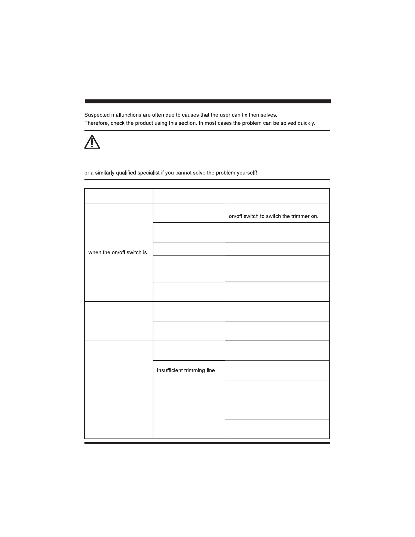
TROUBLESHOOTING
WARNING
Only perform the steps described within these instructions!
All further inspection, maintenance and repair work must be performed by an authorized service center
PROBLEM POSSIBLE CAUSE SOLUTION
Product will not start
depressed.
Lock-off switch is not
pressed.
Press the lock-off switch and press the
The battery is not secure.
To secure the battery pack, make sure
the battery pack clicks into place.
The battery is not charged. Remove and charge the battery pack.
The battery is defective. Replace with a new, charged battery.
Defective trigger
mechanism.
Call Customer Service for assistance
(Toll free number 866-384-8432).
Product does not reach
full power.
Battery pack capacity is
too low.
Charge the battery pack.
Air vents are blocked.
Remove the battery and clean the air
vents.
Unsatisfactory result.
The trimming line is worn
or damaged.
Replace the trimming line. Refer to the
LINE REPLACEMENT section.
Install more line. Refer to the LINE
REPLACEMENT section.
The trimming line is not
guided out of the spool.
Remove the spool and thread the
trimming line to the outside through the
eyelet. Check the line end is not held in
the slot on spool. Replace the spool if
necessary.
Trimming line breaks too
often.
Soak the line in hot water for several
hours to rehydrate it.

31
TROUBLESHOOTING
Unsatisfactory result.
The trimmer head is dirty. Clean the trimmer head.
Battery pack capacity is
too low.
Charge the battery pack.
Cutting tall grass at ground
level.
Cut the tall grass from the top down to
prevent wrapping.
Line will not advance.
The trimming line is worn,
depleted, or tangled.
Install more trimming line. Refer to the
LINE REPLACEMENT section.
The spool is worn.
Replace the spool. Refer to the SPOOL
REPLACEMENT section.
No charging procedure
possible.
The battery contacts are
contaminated.
Clean the battery contacts (e.g. by
inserting and removing the battery
several times) or replace the battery.
Mains plug of battery
charger is not plugged in
properly.
Insert mains plug fully into the socket
outlet.
Socket outlet, mains cable
or battery charger are
defective.
Check the mains voltage and if
necessary, contact the Customer
Service for assistance (Toll free number
866-384-8432).
The battery has a fault.
Contact the Customer Service for
assistance (Toll free number 866-384-
8432).
Charger 2Hz red LED
Battery pack is too hot.
Allow the battery pack to reach normal
temperature. Charging will begin
when battery pack returns to normal
temperature.
For more status of the indicator lights on battery & charger, refer to page 16 & 17.
32
LAWNMASTER
®
WARRANTY
33
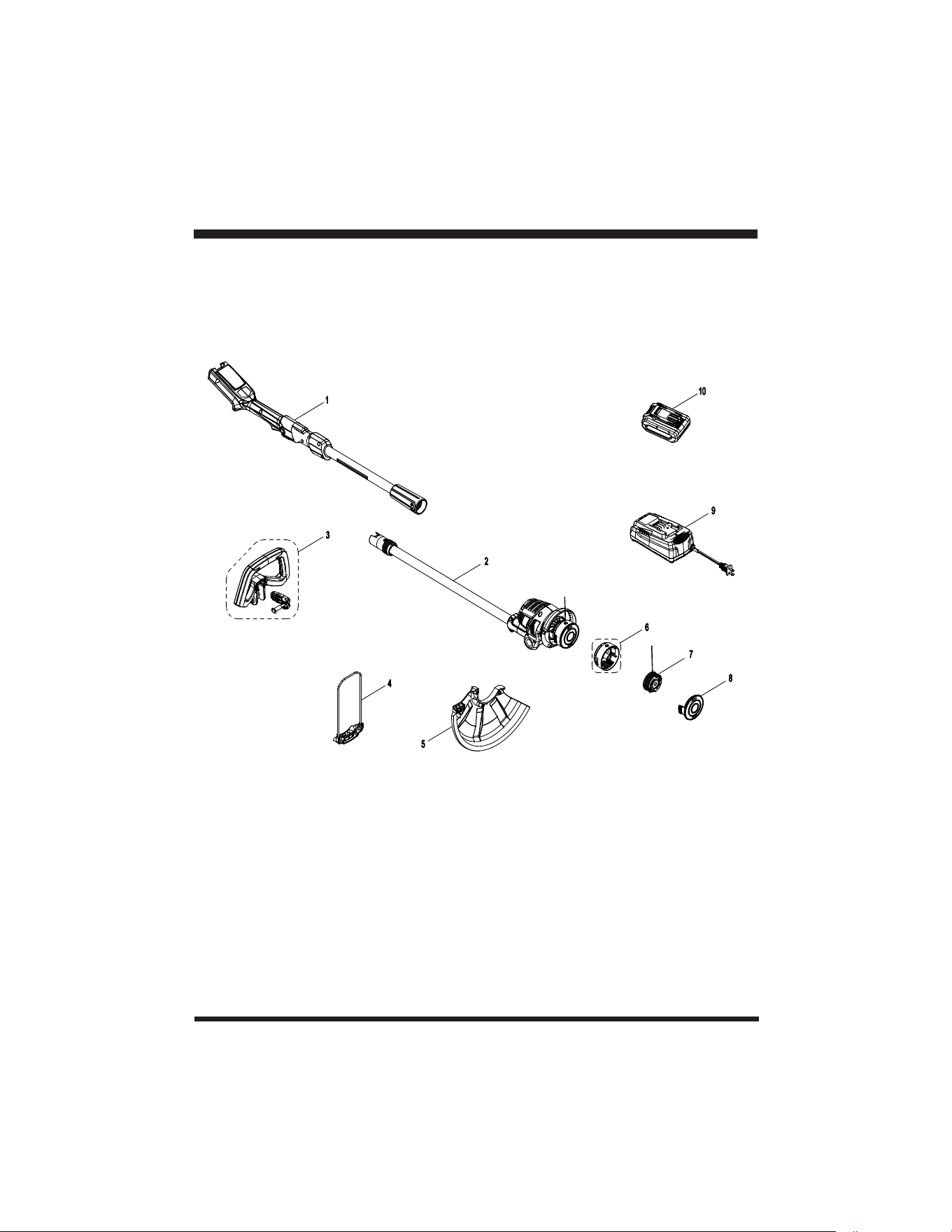
EXPLODED VIEW

34
PARTS LIST
Key Number Drawing Number Description Quantity
1 Main Handle Assembly 1
2 Power Head Assembly 1
3 Auxiliary Handle Assembly 1
4 Flower Guard Assembly 1
5 221043105 Debris Guard 1
6 Spool Holder 1
7 221043107 Spool With Line 1
8 Spool Cover 1
9 221024107 Charger 1
10 221043108 Battery 1
Replacement parts highlighted in grey are available for after sales purchase. Replacement of repair or
service dealer or Customer Service at 866-384-8432.

35
NOTES

36
NOTES
