
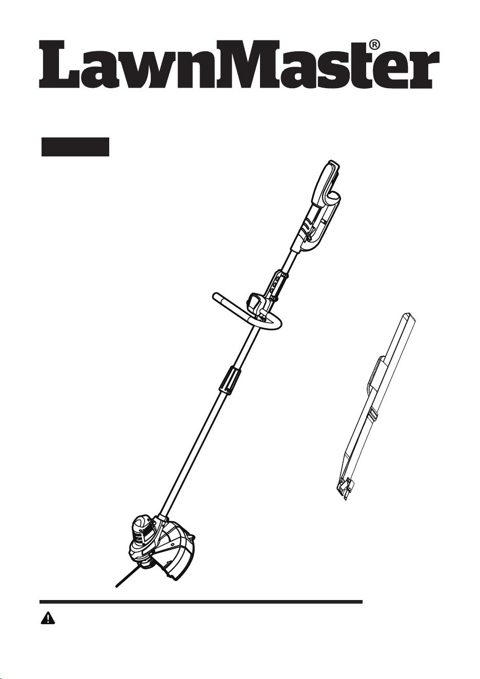
CLGT2412K
Operators Manual
Read all safety rules and instructions carefully before operating this tool.
Distributed By Cleva North America 601 Regent Park Court Greenville, SC 29607 (866)-384-8432
Shoulder Strap Included
40V-12" Li-Ion Cordless Grass Trimmer CLGT4012K
EN p. 2

Type Cordless, Battery-Powered
Rated No Load Speed 7200 r/ min
Line Diameter 0.080" Round Line
Feed System 12" Fixed Line
Cutting Width 12 inch
Weight 7.4 lbs without battery
2
CONTENTS
PRODUCT SPECIFICATIONS
GENERAL SAFETY RULES
ELECTRICAL INFORMATION
SYMBOLS
KNOW YOUR CORDLESS GRASS TRIMMER
ASSEMBLY
OPERATION
MAINTENANCE
TROUBLESHOOTING
WARRANTY POLICY
EXPLODED VIEW
PARTS LIST
NOTES
2
2
3-4
5
6-7
8-9
10-11
12-14
14-15
16
17
18
19
20
CONTENTS
PRODUCT SPECIFICATIONS
40V LITHIUM-ION CORDLESS GRASS TRIMMER

3
GENERAL SAFETY RULES
WARNING
Read and understand all instructions before using this product. Failure to follow all
• Do not operate power tools in explosive atmospheres,such as in the presence of flammable
liquids, gases, or dust. Power tools create sparks which may ignite the dust or fumes.
• Do not allow children or untrained individuals to use this unit.
• Don’t expose power tools to rain or wet conditions. Water entering a power tool will increase the
risk of electric shock.
• Do not handle plug or tool with wet hands.
• Never allow children to operate the equipment. Never allow adults to operate the equipment
without proper instruction.
• Always wear safety glasses with side shields. Everyday glasses have only impact resistant
lenses. They are NOT safety glasses. Following this rule will reduce the risk of eye injury. Use
face mask if operation is dusty.
• Wear eye protection when operating this product. Secure long hair above shoulder level to
prevent entanglement in moving parts.
• Do not expose to rain, store indoors.
• Keep all parts of your body away from any moving part.
• Keep hair,loose clothing,fingers and all body parts away from opening and moving parts.
• Wear heavy long pants, boots, and gloves. Avoid loose garments or jewelry that could get
caught in moving parts of the machine or its motor.
• Do not force tool. Use the correct tool for your application. The correct tool will do the job
better and safer at the rate for which it is designed.
• Do not operate the equipment while barefoot or when wearing sandals or similar lightweight
footwear. Wear protective footwear that will protect your feet and improve your footing on
slippery surfaces.
• Secure long hair so it is above shoulder level to prevent entanglement in any moving parts.
• Keep firm footing and balance. Do not overreach. Overreaching can result in loss balance.
• Do not allow to be used as a toy. Close attention is necessary when used by or near children.
• Do not use tool if switch does not turn it on or off. Any tool that cannot be controlled with the
switch is dangerous and must be repaired.
• Keep all bystanders, children, and pets at least 50 ft. away.
• Do not operate this unit when you are tired,ill, or under the influence of alcohol,drugs,or
medication.
• Do not operate in poor lighting.
• Do not put any object into openings. Do not use with any opening blocked; keep openings free
Of dust,lint,hair,and anything that may reduce air flow.
• Check the work area before each use. Remove all objects such as rocks, broken glass, nails,
wire, or string which can be thrown or become entangled in the machine.

4
GENERAL SAFETY RULES
• Use only identical manufacturer’s replacement parts and accessories. Use of any other parts
may create a hazard or cause product damage.
• Do not charge battery tool in rain, or damp or wet location. Following this rule will reduce the
risk of electric shock.
• For household use only.
• Battery tools do not have to be plugged into an electrical outlet; therefore, they are always in
operating condition. Be aware of possible hazards when not using your battery tool or when
changing accessories. Following this rule will reduce the risk of electric shock,fire,or serious
personal injury.
• Remove or disconnect battery before servicing, cleaning or removing material from the
gardening appliance.
• Store idle appliances - When not in use, grass trimmer should be stored indoors in a dry, locked
place out reach of children.
• Do not dispose of the batteries in fire. The cell may explode. Check with local codes for possible
special disposal instructions.
• Do not place battery tools or their batteries near fire or heat. This will reduce the risk of explosion
and possibly injury.
• Do not open or mutilate the batteries. Released electrolyte is corrosive and may cause damage
to the eyes or skin. It may be toxic if swallowed.
• Batteries can explode in the presence of a source of ignition, such as a pilot light. To reduce
the risk of serious personal injury, never use any cordless product in the presence of open flame.
An exploded battery can propel debris and chemical. If exposed, flush with water immediately.
• Do not crush, drop or damage battery pack. Do not use a battery pack or charger that has
been dropped or received a sharp blow. A damaged battery is subject to explosion. Properly
dispose of a dropped or damaged battery immediately.
• Exercise care in handling batteries in order not to short the battery with conducting materials
such as rings, bracelets, and keys. The battery or conductor may overheat and cause burns.
Do not open or mutilate the batteries. Released electrolyte is corrosive and may cause damage
to the eyes or skin. It may be toxic if swallowed.
• For best results, your battery tool should be charged in a location where the temperature is
more than 50°F but less than 100°F. To reduce the risk of serious personal injury, do not store
outside or in vehicles.
• Under extreme usage or temperature conditions, battery leakage may occur. If liquid comes in
contact with your skin, wash immediately with soap and water, then neutralize with lemon juice
or vinegar. If liquid gets into your eyes, flush them with water with clean water for at least 10
minutes, then seek immediate medical attention. Following this rule will reduce the risk of serious
personal injury.
•

5
ELECTRICAL INFORMATION
The following signal words and meanings are intended to explain the levels of risk associated
with this product.
• If the power supply cord is damaged, it must be replaced only by the manufacturer or by an
authorized service center to avoid risk.
• Do not point the grass trimmer in the direction of people or pets.
• Never run the unit without the proper equipment attached. Always ensure the sweeper tubes
are installed.
• When not in use, grass trimmer should be stored indoors in a dry, locked up place—out of the
reach of children.
• Maintain tool with care. Keep fan area clean for best and safest performance. Follow instructions
for proper maintenance. Do not attempt to clear clogs from tool without first unplugging it.
• To reduce the risk of electrical shock, do not expose to rain, do not use on wet surfaces. Store
indoors.
• Save these instructions. Refer to them frequently and use them to instruct others who may
use this power tool. If you loan someone this power tool, loan them these instructions also.
WARNING (PROPOSITION 65)
Some dust created by power sanding, sawing, grinding, drilling, and other construction activities
contains chemicals known to cause cancer, birth defects or other reproductive harm. Some
examples of these chemicals are:
• Lead from lead-based paints
• Crystalline silica from bricks and cement and other masonry products, and
• Arsenic and chromium from chemically treated lumber.
Your risk of exposure to these chemicals varies depending on how often you do this type of
work. To reduce your exposure to these chemicals, work in a well-ventilated area, and work with
approved safety equipment, such as dust masks that ate specially designed to filter out
microscopic particles.
CHILD SAFETY
Tragic accidents can occur if the operator is not aware of the presence of children.
• Keep children out of the working area and under the watchful care of a responsible adult.
• Do not allow children under the age of 14 to operate this grass trimmer. Children who are 14
years of age and older must read and understand the operating instructions and safety rules
in this manual and must be trained and supervised by a parent.
• Stay alert, and turn the grass trimmer off if a child or any other person enters the working area.
• Look behind and down for small children before and while cutting backwards.
• Use extreme care when approaching blind corners, doorways, shrubs, trees, or other
objects that may obscure your view of a child who may run into the path of the grass trimmer.

6
SYMBOLS
On the product, the rating label and within these instructions you will find among others he following
symbols and abbreviations. Familiarise yourself with them to reduce hazards like personal injuries
and damage to property.
n
o
NOITANALPXE/NOITANGISED EMAN LOBMYS
V Volts Voltage
A Amperes Current
Hz Hertz Frequency (cycles per second)
W Watts Power
hrs Hours Time
No Load Speed Rational speed, at no load
Class II Construction Double-insulated construction
/min Per Minute Revolutions, strokes, surface speed, orbits etc.,
per minute
Designates that this tool is in compliance with
Lithium-Ion battery recycling program requirements
Lithium-Ion Battery
Recycling
Read the Operator’s Manual
Safety Alert Symbol
To reduce the risk of injury, user must read and
understand operator’s manual before using this product.
Eye and Head Protection
Gloves
Safety Footwear
Kickback DANGER! Beware of kickback.
DANGER! Risk of electrocution!
Failure to keep your hands away from the blade will
result in serious personal injury.
Failure to use in dry conditions and to observe safe
practices can result in electric shock.
Risk of Electrocution
Electric Shock
No Hands Symbol
Keep Bystanders Away
Wear eye and head prote
ction when operating this
equipment.
Wear non-slip, heavy-duty protective gloves when
handling the pole saw and the blade.
Wear non-slip safety footwear when using this
equipment.
Precautions that involve your safety.
Keep all bystanders at least 50' (15 m) away.

7
The following signal words and meanings are intended to explain the levels of risk associated with
this product.
Service
Servicing requires extreme care and knowledge and should be performed only by a qualified service
technician. For service we suggest you return the product to your nearest AUTHORIZED SERVICE
CENTER for repair. When servicing, use only identical replacement parts.
WARNING
To avoid serious personal injury, do not attempt to use this product until you have read this Owner's
Manual thoroughly and understand it completely. If you do not understand the warnings and
instructions in this Owner's Manual, do not use this product. Call the Toll-free Helpline
(866)-384- 8432 for assistance. The operation of any power tool can result in foreign objects being
thrown into your eyes, which can result in severe eye damage. Before operating a power tool, always
wear safety goggles, safety glasses with side shields, or a full face shield when needed.
We recommend a Wide Vision Safety Mask for use over eyeglasses or standard safety glasses with
side shields. Always use eye protection that is marked to comply with ANSI Z87.1.
WARNING
The operation of any power tool can result in foreign objects being thrown into your eyes,
which can result in severe eye damage. Before beginning power tool operation, always
wear safety goggles or safety glasses with side shields and, when needed, a full face shield.
DANGER Indicates an imminently hazardous situation, which, if not
avoided, will result in death or serious injury.
WARNING Indicates a potentially hazardous situation, which, if not avoided,
could result in death or serious injury.
CAUTION Indicates a potentially hazardous situation, which, if not avoided,
may result in minor or moderate injury.
CAUTION (Without Safety Alert Symbol) Indicates a situation that may
result in property damage.
SYMBOLS
SAVE THESE INSTRUCTIONS
SYMBOL SIGNAL MEANING
We recommend Wide Vision Safety Mask for use over eyeglasses or standard safety glasses with
side shields. Always use eye protection which is marked to comply with ANSI Z87.1.
8
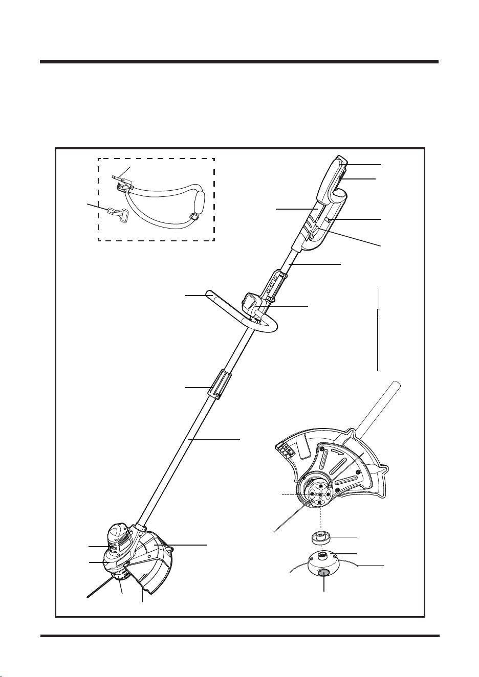
KNOW YOUR CORDLESS GRASS TRIMMER
KNOW YOUR PRODUCT
The safe use of this product requires an understanding of the information on the product and in
this operator’s manual as well as a knowledge of the project you are attempting. Before use of this
product, familiarize yourself with all operating features and safety rules.
6
20
20a
20b
18
16
17
19
15
1
2
3
12
9
15
1a
13
7
10
5
8
11
14
4

KNOW YOUR CORDLESS GRASS TRIMMER
9
Unpack
• Unpack all parts and lay them on a flat, stable surface.
• Remove all packing materials and shipping devices if applicable.
• Make sure the delivery contents are complete and free of any damage. If you find that parts are
missing or show damage do not use the product but contact your dealer. Using an incomplete or
damaged product represents a hazard to people and property.
• Ensure that you have all the accessories and tools needed for assembly and operation. This also
includes suitable personal protective equipment.
NOTE: The above identifier numbers will be used throughout the manual to aid in calling out features.
You Will Need
(items not supplied)
• Suitable personal protective equipment
• Battery pack 40LB4001
• Charger 40LC01-ETL
(items supplied)
• Hardware pack (Trimmer Head, Backing Flange, Spindle Locking Rod, 10pcs – 12” .080” line)
• Shoulder strap
• Safety Guard
• Upper Shaft
• Lower Shaft w/ Motor
• Front Handle (J-Handle)
1. Battery Dock
1 a. Slot
2. Rear Handle
3. On/off Switch
4. Lock-off Button
5. Upper Shaft
6. Spindle Lock Rod
7. Front Handle (J-handle)
8. Front Handle Connector
9. Line Cutting Knife
10. Locking Collar
11. Lower Shaft
12. Motor Housing
13. Air Vents
14. Safety Guard
15. Fixed Line Trimmer Head
16. Release Button
17. Trimmer Line (2mm/.08”)
18. Spindle
19. Backing Flange
20. Shoulder Strap
20a. Clasp Release Bar
20b. Snap Clip
10
ASSEMBLY
WARNING
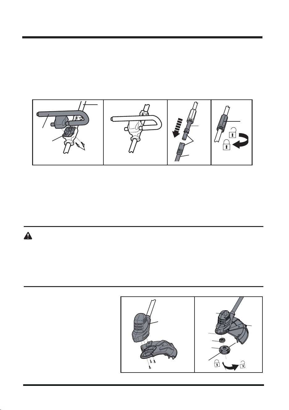
J-handle
NOTE: The 2 screws needed for attaching the J handle to the upper shaft are found already in the
J handle. They must be removed for installation.
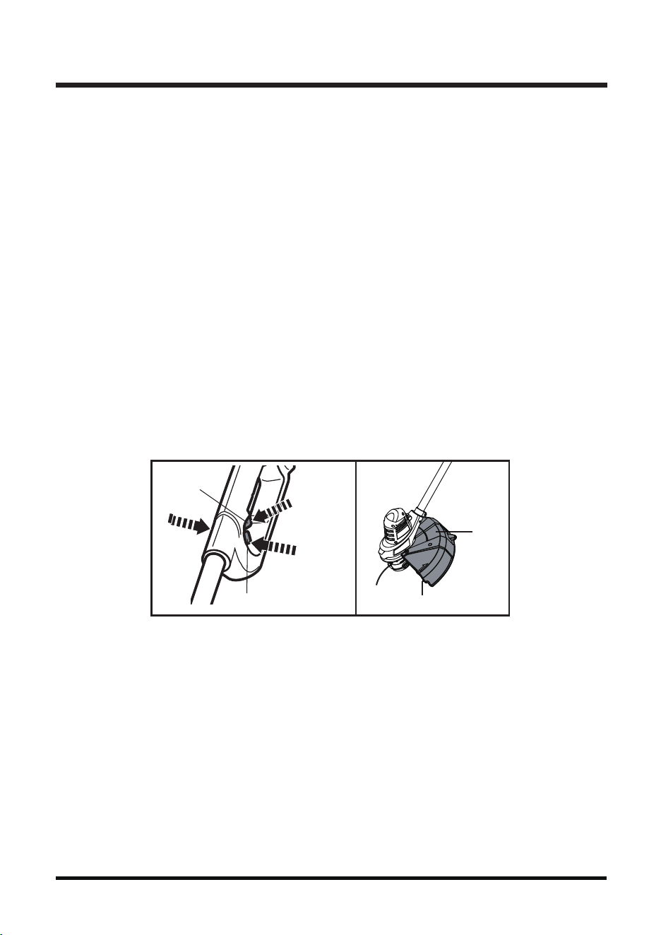
1. Align the J-handle with the front handle connector on the upper shaft (Fig. 1).
2. Attach the J-handle to the front handle connector on the upper shaft and fasten it with screws (Fig. 2).
Shaft
1. Align the upper shaft with the lower shaft . The triangle-shaped recesses must face each other
(Fig. 3).
2. Insert the upper shaft into the lower shaft.
3. Fasten both shafts with the locking collar (Fig. 4).
NOTE: The 3 screws for attaching
the guard to the motor housing are
found already in the motor housing.
They must be removed for installation.
The product must be fully assembled before operation! Do not use a product that is only
partly assembled or assembled with damaged parts! Follow the assembly instructions
step-by-step and use the pictures provided as a visual guide to easily assemble the
product! Do not connect the product to power supply before it is completely assembled!
Failure to heed this warning could result in serious personal injury.
Fig. 1
5
Screws
7
8
Fig. 2
Fig. 3 Fig. 4
5
11
A
10
Fig. 5
12
Screws
Fig. 6
16
19
14
12
18
Safety Guard
Attach the safety guard to the gear
head and fix it with screws (Fig. 5).
11
ASSEMBLY
WARNING
This product must be used with all safety guards installed at all times.
Failure to heed this warning could result in serious personal injury.
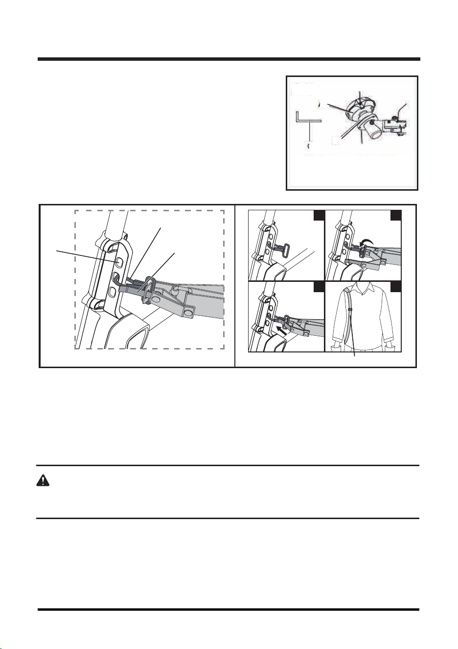
Fixed Line Trimmer Head
1. Make sure that the safety guard has been attached properly.
2. Rotate the backing flange until its hole is aligned with the
notch in the gear head.
3. Insert the spindle lock rod into the hole to lock the spindle.
4. Screw the trimmer head anticlockwise on the spindle (Fig. 6).
5. Remove the spindle lock rod.
Shoulder Strap
The shoulder strap helps the operator to carry the product.
1. Attach the snap clip to one of the three connection points most suitable to your height (Fig. 7).
2. To remove the shoulder strap from the loop, pull the clasp release bar back and out of the hole.
3. Install and place the shoulder strap as show below (Fig. 8).
Fig. 7
A
20b
20a
Fig. 8
20
1
3
2
4
A - Trimming Head (Cabeza de bordeadora)
B - Backing Flange (Reborde trasero)
C - Spindle Lock Rod(Vara de bloqueo del eje rotor)
A
B
C
12
OPERATION
Intended Use
This cordless grass trimmer is designated with rated voltage of 36V D.C. . It is designed only to be
used with battery packs 40LB4001. The fixed line trimmer head installed on this product is intended
to cut smaller types of weed, lawn grass or similar soft vegetation in areas that are hard to reach,
e.g. under bushes, on slopes and edges. It may not be used to work on unusual thick, dry or wet
grass, e.g. pasture grass, or to shred leaves. For safety reasons it is essential to read the entire
instruction manual before first operation and to observe all the instructions therein. This product is
intended for private domestic use only, not for any commercial trade use. It must not be used for
any purposes other than those described.
ON / OFF Switch
1. Press the lock-off button on either side and hold it in position (Fig. 9, STEP 1).
2. Press the on/off switch to switch the product on (Fig. 9, STEP 2). The lock-off button can then
be released.
3. Release the on/off switch to switch the product off.
Safety Guard
Safety guard protects the operator against thrown objects during operation. The safety guard is
equipped with a line cutting knife that cuts excess trimming line (Fig. 10).
General Operation
• Check the product, its battery pack and charger as well as accessories for damage before each
use. Do not use the product if it is damaged or shows wear.
• Double check that accessories or cutting device are properly fixed.
• Always hold the product by its handles. Keep the handles dry and free from lubricant to ensure
safe support.
• Ensure that the air vents are always unobstructed and clear. Clean them if necessary with a soft
brush. Blocked air vents may lead to overheating and damage the product.
• Switch the product off immediately if you are disturbed while working by other people entering the
working area. Always let the product come to complete stop before putting it down.
• Do not overwork yourself. Take regular breaks to ensure you can concentrate on the work and
have full control over the product.
Fig. 9 Fig. 10
STEP 2
STEP 1
3
4
9
15
13
OPERATION
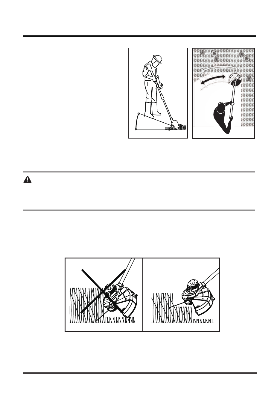
Trimming
• Attach the trimming head to cut smaller
types of weed, lawn grass or similar soft
vegetation.
• Hold the product firmly with a gap between
the product and your right side.
• Stand upright, do not lean forward and
pay attention to posture. Keep both feet
apart to help retain your balance.
• Hold the trimming head just above the
ground at an angle of approximately 30°
(Fig. 11). Avoid pressing it against the
ground as this can ruin the lawn and damage the product.
• Move the product with a slow regular arc from left to right before moving it back to the starting
position and trimming the next area (Fig. 12).
WARNING
To avoid hazards, remove the battery pack when the user wants to transport the product in
another area to prevent a random start. Failure to heed this warning could result in serious
personal injury.
• Ensure the cutting device remains clean and free from off-cuts that may cause it to jam. Check
regularly. Release the on/off switch and remove the battery pack before checking.
• Trim longer grass in stages; do not cut long grass in one cut (Fig. 13). For the best results, cut
longer grass in steps (Fig. 14).
• Wait until the product has come to a standstill before placing it down.
Tips
• For best results, do not cut wet grass because it tends to stick to the trimming head and guard,
prevents proper discharge of grass trimmings, and could cause you to slip and fall.
Fig. 11
30°
Fig. 13 Fig. 14
Fig. 12

14
OPERATION
MAINTENANCE
WARNING
To Reduce The Risk Of Injury Or Damage:
• Pay special attention when performing the work close to trees and
bushes. The trimming head could damage sensitive bark, and
damage fence posts (Fig. 15).
• Carefully maneuver the product around objects, such as trees and
bushes, ensuring it does not come into contact with them.
After Use
• Switch the product off, remove the battery back and let it cool down.
• Check, clean and store the product as described below.
• Always switch the product off, remove the battery pack and let the product cool down before
performing inspection, maintenance and cleaning work!
• Only perform repairs and maintenance work according to these instructions! All further works
must be performed by a qualified specialist!
• Do not use chemical, alkaline, abrasive or other aggressive detergents or disinfectants to clean
this product as they might be harmful to its surfaces.
• Wear safety gloves when working on the cutting device and close to it! Use appropriate tools to
remove debris e.g. a brush or wooden stick! Never use your bare hands!
• Always use original spare parts for replacement. The trimmer head MUST be replaced with an
identical replacement part! Do not attach any other type of trimming device!
• Please consult the instructions for use supplied with the battery pack and charger for more detail.
General Care
• Keep the product clean. Remove debris from it after each use and before storage.
• Regular and proper cleaning will help ensure safe use and prolong the life of the product.
• Inspect the product before each use for worn and damaged parts. Do not operate it if you find
broken and worn parts.
General Cleaning
• Clean the product with a dry cloth. Use a brush for areas that are hard to reach.
• In particular clean the air vents after every use with a cloth and brush.
• Remove stubborn dust with high pressure air (max. 3 bar).
Fig.15
15
MAINTENANCE
Replacing The Trimmer Head
• Lay the product on a flat stable surface with the trimmer head (16) facing upward.
• Rotate the backing flange until one of the notches is aligned with the hole in the gear head.
• Insert the spindle lock rod into the hole to lock the spindle.
• Unscrew the trimmer head (16) clockwise.
• Refit the trimmer head (16) to the spindle as described in section “Assembly –Trimmer Head ”.
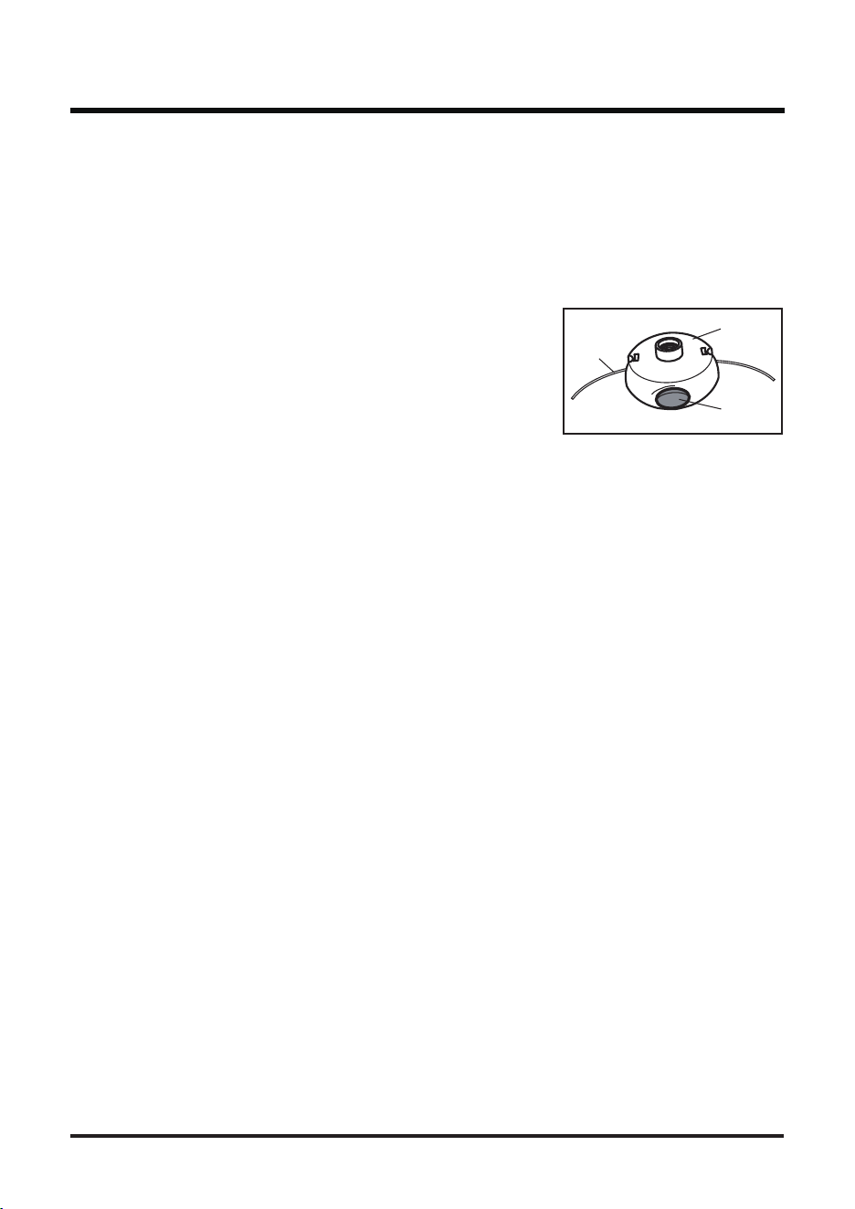
Refilling Trimmer Line
• Press and hold the release button on the trimmer head (16) housing.
The trimmer line can be replaced while the button is pressed .
• After inserting new trimmer line, make sure it sticks out evenly off
the trimmer head (Fig. 16).
NOTE: Always use .080" (2mm) round trimmer monofilament line as replacement line. OR buy 12 inch
pre-cut .080" round line at your nearest retailer.
Safety Guard
• Keep the safety guard clean and free of debris. Remove trimmings.
• Replace the safety guard with one of the same type when it is worn or shows damage.
Repair
This product does not contain any parts that can be repaired by the consumer. Contact an
authorized service center or a similarly qualified person to have it checked and repaired.
Storage
• Clean the product as described above.
• Store the product and its accessories in a dry, frost-free place.
• Always store the product in a place that is inaccessible to children. The ideal storage temperature
is between 10 and 30°C.
• We recommend using the original package for storage or covering the product with a suitable
cloth or enclosure to protect it against dust.
Transportation
• Switch the product off and remove the battery pack before transporting it anywhere.
• Attach other transportation guards, if applicable.
• Always carry the product by its gripping handles.
• Protect the product from any heavy impact or strong vibrations which may occur during
transportation in vehicles.
• Secure the product to prevent it from slipping or falling over.
Fig.16
16a
16
17

16
TROUBLESHOOTING
1. Product does not
start
2. Product does not
reach full power
3. Unsatisfactory
result
1.1. Battery pack not properly
attached
1.2. Battery pack discharged
1.3. Battery pack damaged
1.4. Other electrical defect to
the product
2.1. Battery pack capacity too low
2.2. Air vents are blocked
3.1. Trimming device is worn
1.1. Attach properly
1.2. Remove and charge
battery pack
1.3. Check by a specialist
electrician
1.4. Check by a specialist
electrician
2.1. Charge battery pack
2.2. Clean the air vents
3.1 Replace with a new one
Problem Possible Cause Solution

17
WARRANTY POLICY
We take pride in producing a high quality, reliable product. That’s why LawnMaster tools carry a
limited two (2) year warranty against defects in workmanship and materials from date of purchase
under normal household use. If product is to be used for commercial, industrial or rental use, a thirty
(30) day limited warranty will apply. Batteries and chargers carry a limited one (1) year warranty
against defects in workmanship and materials.
Returning Product for Warranty:
• Dated proof of purchase is required for warranty service.
• Please register your product on www.lawnmaster.com.
• Contact Customer Service at (866) 384-8432 to initiate the warranty process.
• Shipping and processing fees may apply.
Not Covered by Warranty:
• Any part that has become inoperative due to misuse, negligence, direct/indirect abuse,
accidents, improper maintenance, repairs or alteration;
• Batteries that are not charged in accordance with the operator's manual directions and regulations;
• Any parts subject to normal wear and tear including but not limited to: the spool of trimmer line,
trimmer head spool cover, mower blade, collection bag, brush cutter blade, pole saw chain and
guide bar;
• The unit, if it has not been operated and/or maintained in accordance with the operator's manual;
• Normal wear and tear;
• Routine maintenance items such as lubricants, blade sharpening;
• Normal deterioration of the exterior finish due to use or exposure;
• Any product where serial number/data label is tampered with or removed;
• Any product purchased from unauthorized retailers.
This warranty gives you specific legal rights, and you may have other rights,
which vary from state to state.
18
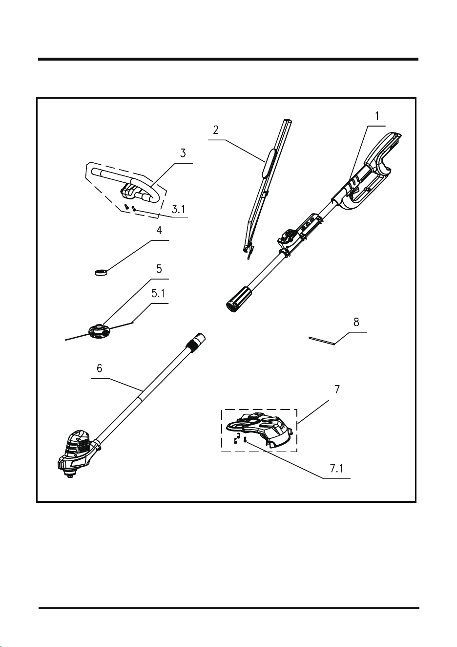
EXPLODED VIEW
CLGT4012K EXPLODED VIEW

19
PARTS LIST
CLGT4012K PARTS LIST
QTY
1
2
3
3.1
4
5
5.1
6
7
7.1
8
GE71DC.10.00
GE70DC.00.16
GE71DC.40.00
BOA1XP.50.16
EA34FA.40.02
GE70DC.50.05.X1.03
FG1131.09.01
GE71DC.20.03.X1.01
GE01BC.50.10.X1.01
BOA1SP.50.12.BX
GE70DC.00.09
Rear Handle
Shoulder Strap
J-handle
Screw
Backing Flange
Fixed Line Trimmer Head
Trimmer Line
Front Handle w/ Motor Assembly
Safety Guard Assembly
Screw
Spindle Lock Rod
1
1
1
2
1
1
10
1
1
3
1
NO. PART NO. PART DESCRPTION

20
NOTES
