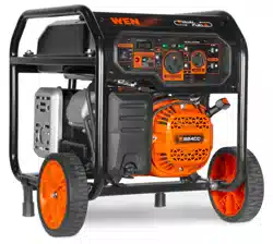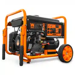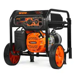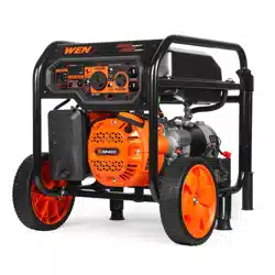
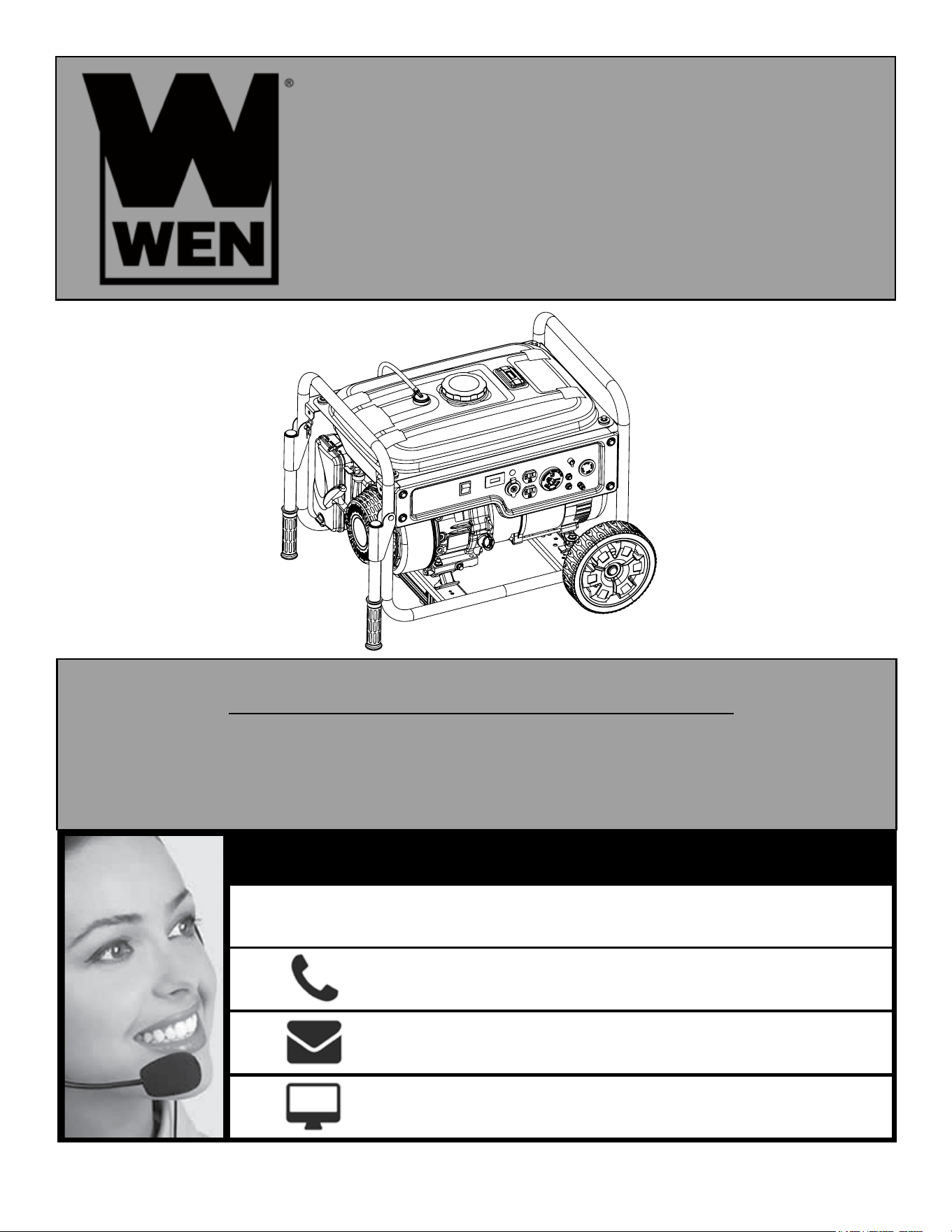
5000W PORTABLE
GENERATOR
Your new tool has been engineered and manufactured to WEN’s highest standards for dependability, ease
of operation, and operator safety. When properly cared for, this product will supply you years of rugged,
trouble-free performance. Pay close attention to the rules for safe operation, warnings, and cautions. If you
use your tool properly and for its intended purpose, you will enjoy years of safe, reliable service.
IMPORTANT:
NEED HELP? CONTACT US!
Have product questions? Need technical support?
Please feel free to contact us at:
800-232-1195
WENPRODUCTS.COM
(M-F 8AM-5PM CST)
Model # 56500
bit.ly/wenvideo
For replacement parts visit
WENPRODUCTS.COM
NOTICE: Please refer to wenproducts.com for the most up-to-date instruction manual.

TABLE OF CONTENTS
2
Generator Identification
3
3
4
4
6
8
9
10
12
14
16
17
22
23
24
25
26
30
Service Record
Introduction
Safety Information
Generator Safety Rules
Unpacking & Assembly
Starting the Generator
Using the Generator
Stopping the Generator
Maintenance
Storage & Transport
Specifications
Wiring Diagram
Troubleshooting
Warranty Statement
Exploded View & Parts List
Generator Preparation
Know Your Generator
If any assistance for information or service is required, please contact our Customer Service Help Line at
(800) 232-1195, M-F 8-5 CST; customer will be asked to provide generator information when calling.
Refer to the illustration below for the location of the serial number. Record generator information in the spaces
provided below.
DATE OF PURCHASE: ______________________________________________
PURCHASED FROM: ______________________________________________
ENGINE SERIAL NUMBER: _________________________________________
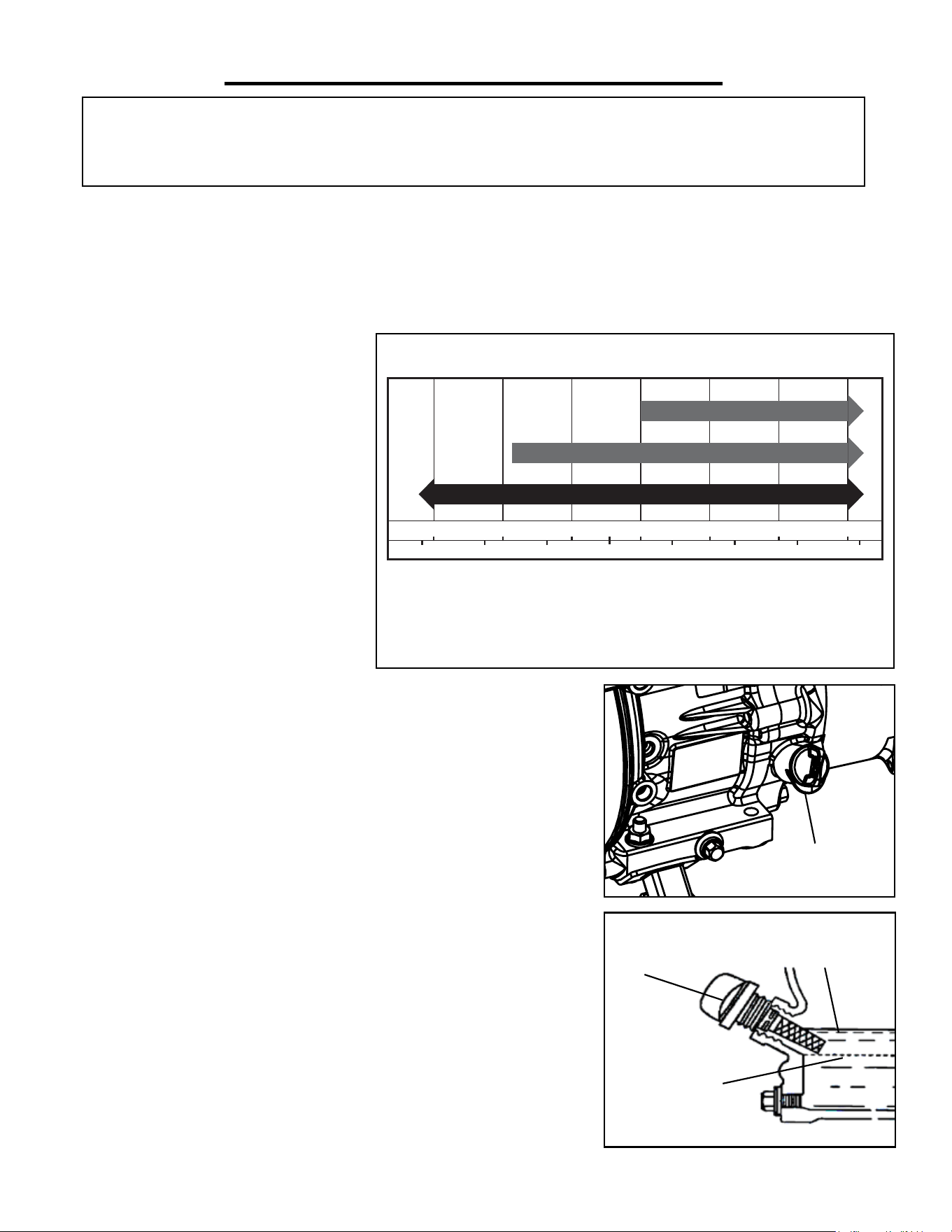
SERVICE RECORD
Record Service Dates:
Date Date Date Date Date Date
Change Oil
Change Spark Plug
Clean Fuel Tank
Clean Air Filter
3
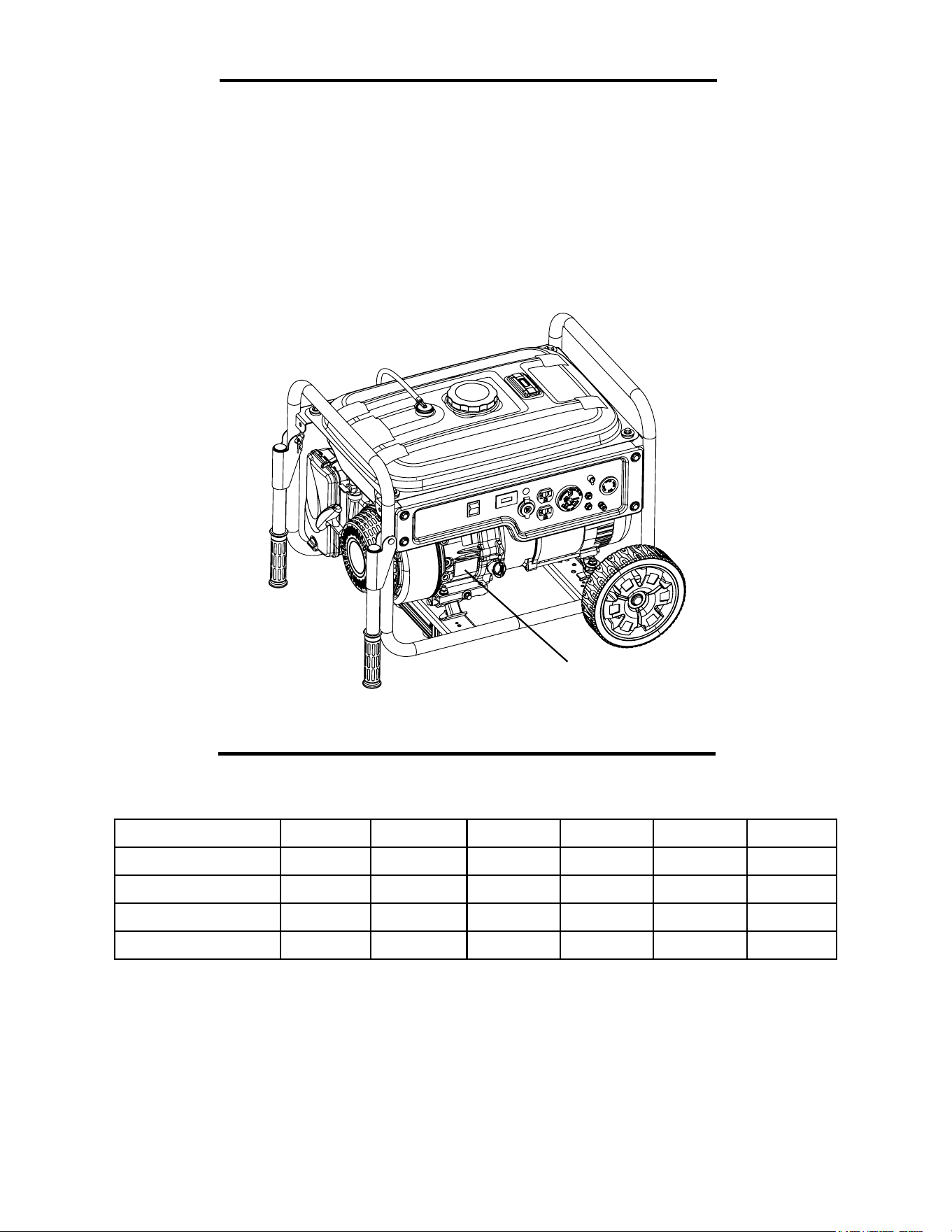
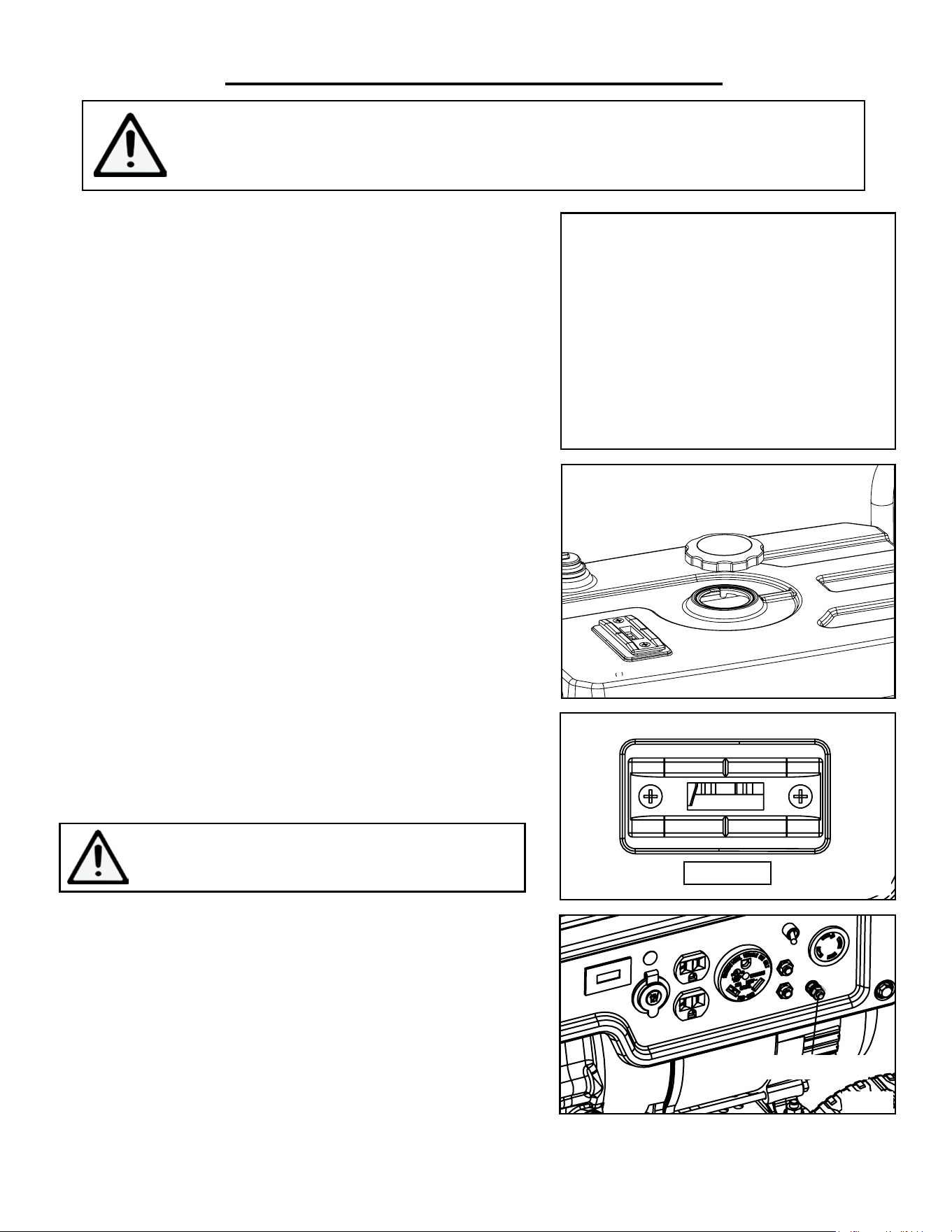
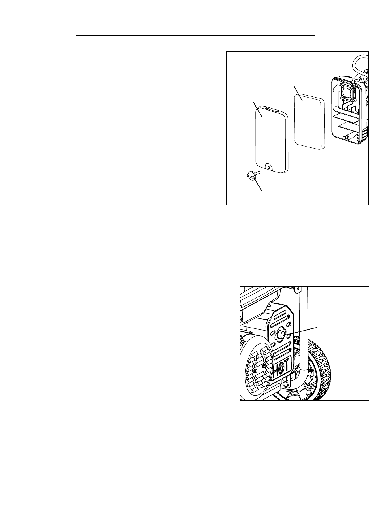
GENERATOR IDENTIFICATION
Serial Number
TO MAXIMIZE THE LIFESPAN OF THIS GENERATOR, MAKE SURE TO RUN IT
AT LEAST ONCE A MONTH. IF YOU DO NOT RUN IT OFTEN, IT WILL GREAT-
LY SHORTEN THE LIFESPAN AND PERFORMANCE OF THE GENERATOR.
4
The safety alert symbol is used to identify safety information about hazards that can result in personal injury.
DANGER: indicates a hazard, which, if not avoided, will result in death or serious injury.
WARNING: indicates a hazard, which, if not avoided, could result in death or serious injury.
CAUTION: indicates a hazard, which, if not avoided, might result in minor or moderate injury.
CAUTION: when used without the alert symbol, indicates a situation that could result in damage to the machine.
The following safety information is not meant to cover all possible conditions and situations that may occur. WEN
reserves the right to change this product and specifications at any time without prior notice.
SAFETY INFORMATION
A signal word (DANGER, WARNING, or CAUTION) is used with the alert symbol to
indicate the likelihood and the potential severity of injury. In addition, a hazard symbol may
be used to represent the type of hazard.
Thank you for purchasing a WEN Generator. Before operating this generator, be sure to read and observe all
warnings, cautions, and instructions both on the generator and in this owner’s manual. Safety is a combination of
common sense, staying alert, and knowing how your tool works. This manual provides information regarding the
safe operation and maintenance of this product. Failure to follow all instructions listed below may result in per-
sonal injury.
Please keep this manual available to all users during the entire life of the tool. Review it frequently to maximize
safety for both yourself and others.
QUESTIONS? PROBLEMS?
In order to answer questions and solve problems in the most efficient and speedy manner, contact Customer
Service at (800) 232-1195, M-F 8-5 CST or email [email protected].
NOTICE REGARDING EMISSIONS
Engines that are certified to comply with U.S. EPA emission regulations for SORE (Small Off Road Equipment),
are certified to operate on regular unleaded gasoline, and may include the following emission control systems:
(EM) Engine Modifications and (TWC) Three-Way Catalyst (if so equipped).
INTRODUCTION
IMPORTANT: This manual contains special messages to bring attention to potential
safety concerns and generator damage as well as helpful operating and servicing information.
Please read all the information carefully to avoid injury and machine damage.
DANGER: CARBON MONOXIDE
Using a generator indoors CAN KILL YOU IN MINUTES. Generator exhaust contains carbon mon-
oxide (CO). This is a poison gas you cannot see or smell. If you can smell the generator exhaust, you are
breathing CO. But even if you cannot smell the exhaust, you could be breathing CO.
NEVER use a generator inside homes, garages, crawl spaces, or other partially enclosed areas. Deadly
levels of carbon monoxide can build up in these areas. Using a fan or opening windows and doors does
NOT supply enough fresh air. ONLY use a generator outside and far away from windows, doors, and
vents. These openings can pull in generator exhaust.
Even if you use a generator correctly, CO may leak into the home. ALWAYS use a battery-powered or
battery-backup CO alarm in the home. If you start to feel sick, dizzy, or weak after the generator has been
running, move to fresh air RIGHT AWAY. See a doctor. You may have carbon monoxide poisoning.
5
SAFETY INFORMATION
WARNING: The exhaust from this product contains chemicals known to the State of Califor-
nia to cause cancer, birth defects, or other reproductive harm.
WARNING: This generator may emit highly flammable and explosive gasoline vapors, which
can cause severe burns or even death if ignited. A nearby open flame can lead to explosion even
if it isn’t directly in contact with gasoline.
WARNING: If this generator is used as a supply for a building’s wiring system, the generator
must be installed by a qualified electrician and connected to a transfer switch as a separately de-
rived system in accordance with the National Electrical Code, NFPA 70. The generator shall be
connected to a transfer switch that switches all conductors excluding the equipment grounding
conductor. The frame of the generator shall be connected to an approved grounding electrode.
WARNING: This generator produces heat when running. Temperatures near exhaust can ex-
ceed 150
0
F (65
0
C). DO NOT TOUCH HOT SURFACE.
NOTE: For power outages, permanently installed stationary generators are better suited for providing backup
power to the home. Even a properly connected portable generator can become overloaded. This may result in
overheating or stressing of the components, possibly leading to a generator failure.
SAVE THESE INSTRUCTIONS – This manual contains important instructions for the WEN generator that
should be followed during installation and maintenance of the generator. DO NOT operate this generator until you
have read all safety operation and maintenance instructions listed in this manual.
For any questions regarding the hazard and safety notices listed in this manual or on the product, please call cus-
tomer service at (800) 232-1195 M-F 8-5 CST or email [email protected] before using the generator.

6
GENERATOR SAFETY RULES
WARNING! Read all safety warnings and all instructions. Failure to follow the warnings and instruc-
tions may result in electric shock, fire and serious injury. To avoid mistakes and serious injury, do not
plug in your tool until the following steps have been read and understood.
OPERATING ENVIRONMENT
1. ONLY use a generator outside and far away from windows, doors and vents. Using a generator indoors can kill
you in minutes.
2. DO NOT operate near open flame or flammable materials. This generator may emit highly flammable and ex-
plosive gasoline vapors, which can cause severe burns or even death if ignited.
3. DO NOT smoke near the generator.
4. DO NOT use the generator in rainy or wet conditions; doing so significantly increases the risk of electrical shock.
5. Always operate the generator on a dry, firm, level surface.
6. DO NOT allow children or non-qualified persons to operate the generator.
GENERATOR PREPARATION
1. ALWAYS ground the generator before using it (see the “Ground the Generator” portion of the “Generator
Preparation” section on page 10).
2. DO NOT overfill fuel tank. Gasoline may expand during operation. Do not fill to the top of the tank. Allow for
expansion.
3. Always check for spilled fuel before operating.
4. Make sure to have damaged items repaired or replaced before operation.
5. DO NOT use plugs or cords that show signs of damage such as broken or cracked insulation.
6. Use a ground fault circuit interrupter (GFCI) in highly conductive areas such as metal decking or steel work. GF-
CIs are available in-line with some extension cords.
7. NEVER connect the generator to a building’s electrical system without a qualified electrician. Such connections
must comply with local electrical laws and codes. Failure to comply can create a back-feed, which may result in seri-
ous injury or death to utility workers.

GENERATOR SAFETY RULES
GENERATOR OPERATION
1. Only use generator for its intended purposes.
2. DO NOT touch bare wires or receptacles (outlets).
3. DO NOT touch hot surfaces. See warning labels on the generator identifying hot parts of the machine.
4. Allow generator to run for several minutes before connecting electrical devices.
5. DO NOT exceed the wattage capacity of the generator by plugging in more electrical devices than the unit can
handle.
6. DO NOT turn on electrical devices until after they are connected to the generator.
7. Generators vibrate in normal use. During and after the use of the generator, inspect both the generator as well as
extension and power supply cords for damage resulting from vibration.
8. Have damaged items repaired or replaced as necessary. Do not use plugs or cords that show signs of damage
such as broken or cracked insulation.
9. Allow generator to cool down after use before touching engine or areas of the generator that become hot during
use.
10. Turn OFF all connected electrical devices before stopping the generator.
11. Shut off and disconnect any malfunctioning devices from generator.
12. Always turn generator OFF before refueling. Allow generator to cool for at least 2 minutes before removing fuel
cap. Loosen cap slowly to relieve pressure in tank.
13. Turn the engine switch to “OFF” position when the engine is not running.
14. Empty fuel tank before storing or transporting the generator.
CAUTION: Misuse of this generator can damage it or shorten its lifespan.
7
TO MAXIMIZE THE LIFESPAN OF THIS GENERATOR, MAKE SURE TO RUN IT
AT LEAST ONCE A MONTH. IF YOU DO NOT RUN IT OFTEN, IT WILL GREAT-
LY SHORTEN THE LIFESPAN AND PERFORMANCE OF THE GENERATOR.
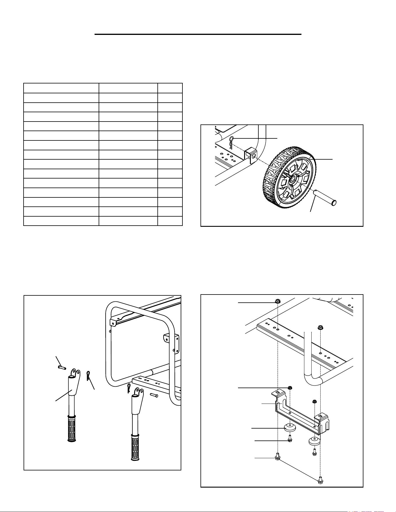
To unpack the generator, first place the shipping carton on a solid, flat ground. Cut open the box from the four
edges and take out all the contents from the carton except for the generator itself. Follow the instructions below to
assemble your generator with the help of a friend or a trustworthy foe.
UNPACKING & ASSEMBLY
INSTALLING THE WHEELS
Slide the M16 x 85 wheel axle through the wheel and
wheel mounting bracket on the bottom of the generator
frame. Insert the wheel cotter pin through the wheel axle
to secure the wheel in place. Repeat with the other wheel.
INSTALLING THE HANDLE ASSEMBLIES
Insert the M10×40 handle axle through the handle
assembly and handle mounting bracket on the gen-
erator frame. Insert the handle cotter pin through
the handle axle to secure the handle in place.
Repeat with the other handle assembly.
INSTALLING THE SUPPORT BRACKET
1. Attach the two rubber feet onto the support bracket
using two M6x16 screws and M6 nuts.
2. Attach the support bracket onto the bottom of the
generator frame using two M8x16 screws and M8 nuts.
Wheel Cotter Pin
Wheel
Wheel Axle
Handle Pin
Handle
Handle
Cotter Pin
Rubber Foot
M8x16 Screw
M6x16 Screw
Support Bracket
M6 Nut
M8 Nut
PACKING LIST
Accessory Part No. Qty.
Wheel 56500-008 2
Wheel Axle M16x85 56500-009 2
Wheel Cotter Pin 56500-007 2
Handle Assembly 56500-001 2
Handle Axle M10x30 56500-005 2
Handle Cotter Pin 56500-003 2
Support Bracket 56500-058 2
Support Foot 56500-059 2
Screw M6x16 56500-054 2
Nut M6 56500-057 2
Screw M8x16 56500-060 2
Nut M8 56500-055 2
Wrench M10/M12 N/A 1
Spark Plug Socket N/A 1
8
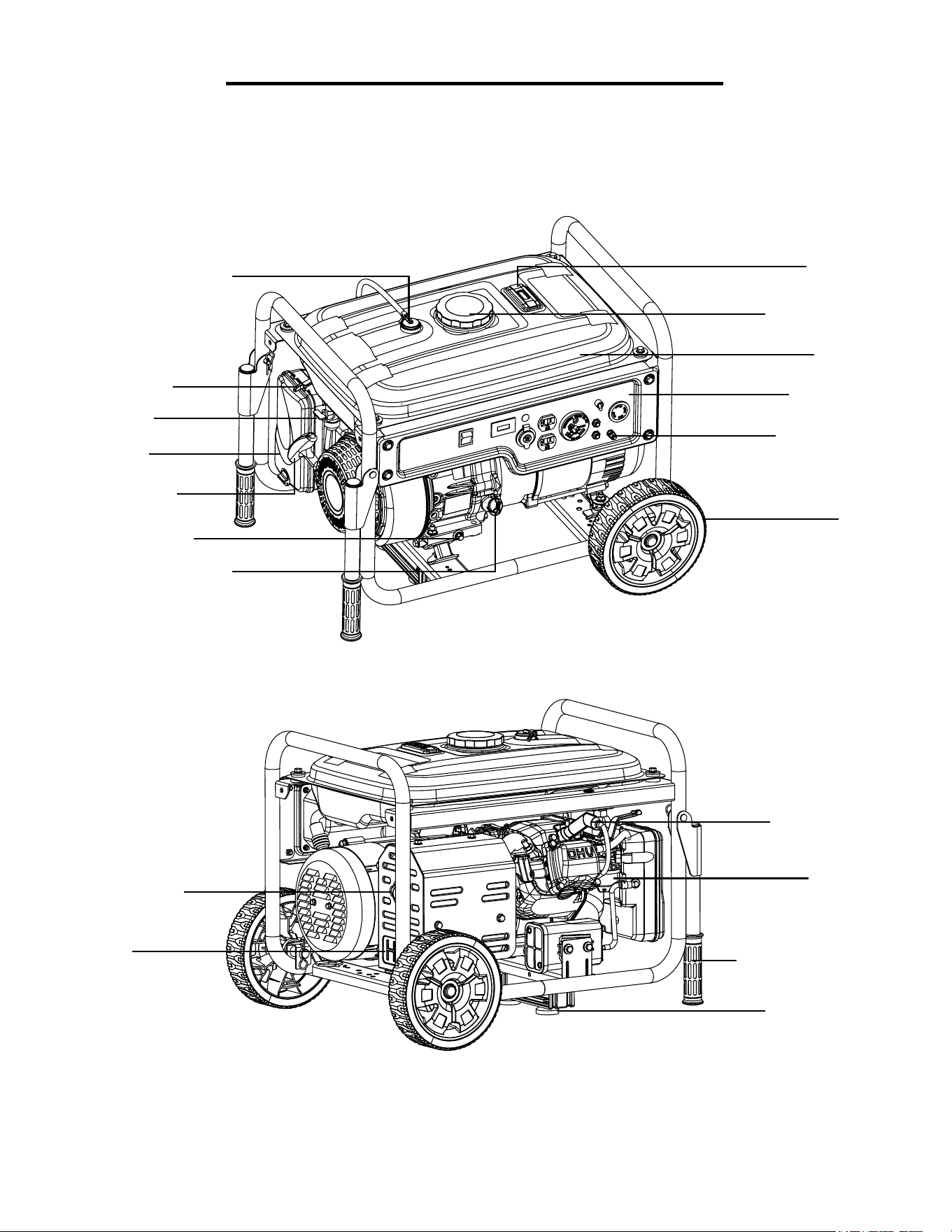
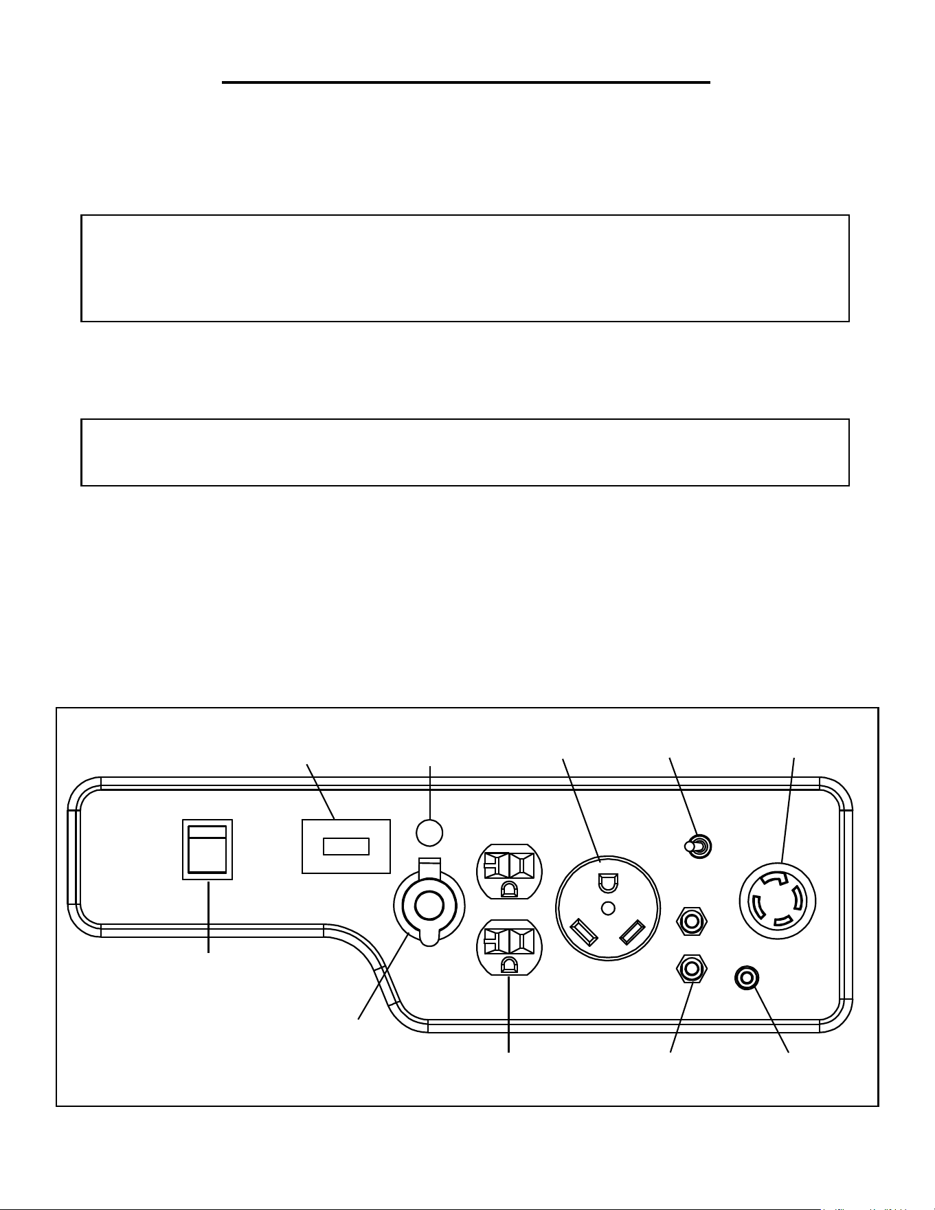
KNOW YOUR GENERATOR
Use the illustration below to become familiar with the locations and functions of the various components of this
generator. If any part is damaged or missing, please contact our customer service at (800) 232-1195, M-F 8-5 CST
or email [email protected].
Muffler
Spark Arrestor
Carburetor
Spark Plug Boot
Fuel Gauge
Fuel Tank
Wheel
Oil Fill with Dipstick
Oil Drain Screw
Pressure Relief Valve
Fuel Tank Cover
Control Panel
Air Filter
Transporting Handle
Support Bracket
Choke Lever
Recoil Starter
Fuel Valve
Grounding Nut
9
STEP 1 - ADD/CHECK OIL
The generator is shipped without oil. A proper amount of oil must be added before operating the generator for
the first time. For subsequent operation, the oil level should be checked before each use or after every 8 hours of
operation. This is a critical step for proper engine starting to ensure that the engine crankcase contains sufficient
lubricant. The oil capacity of the engine crankcase is 33.8 fl. ounces.
GENERATOR PREPARATION
CAUTION: The Generator Preparation Section describes the necessary steps to prepare the generator
for use. If you have any questions after reading this section, please call (800) 232-1195 M-F 8-5 CST for
customer service. Failure to perform these steps properly can damage the generator or shorten its life.
Oil Dipstick
Oil
Dipstick
Lower Level
Fill Line
Upper Level
Fill Line
32
-30 -20 -10 0 10 20 30
-20 0 20 40 60 80 100
40
°F
°C
Synthetic 5W-30
30
10W-30
• 30W, 4-stroke engine oil for temperatures above 40°F.
• 10W-30 engine oil for temperatures between 0°F - 40°F.
• Synthetic 5W-30 engine oil for all temperature ranges.
Fig. 2
Fig. 1
Fig. 3
Select good quality detergent oil bearing
the American Petroleum Institute (API)
service classifications SJ, SL, or SM (syn-
thetic oils may be used). Select the SAE
viscosity grade of oil from “Engine Oil
Recommendations” (Fig. 1) that matches
the expected operating temperature.
To fill oil, follow these steps:
1. Make sure the generator is shut off.
Place the generator on a level surface.
NOTE: Tilting the generator to assist in
filling will cause oil to flow into the engine
areas and will cause damage. Keep the
generator level!
ENGINE OIL RECOMMENDATIONS
2. Remove the oil dipstick from the engine (Fig. 2).
3. Using an oil funnel or appropriate dispenser, slowly add oil into the
oil fill. Fill the crank case to the upper fill line so you can visually see
the oil coming halfway up the oil fill threads (Fig. 3). The oil capacity
of the engine crankcase is 33.8 fl. ounces. Be careful not to overfill the
unit.
4. Reinstall the oil dipstick and wipe clean any spilled oil with a dry rag.
To check/add oil, follow these steps:
1. Remove and wipe the oil dipstick with a clean rag. Insert the dipstick
into the oil fill opening without screwing it in.
2. Remove the dipstick to check the oil mark on the dipstick. Add oil if
the oil mark covers less than one half of the dipstick.
3. Slowly add oil and repeat step 2 until the oil mark reaches to the top
of dipstick (or when you can see the oil coming halfway up the oil fill
threads). Do not over fill the crankcase.
4. Wipe clean any oil leaks and firmly tighten the dipstick.
10
After completing the above preparation, the generator is ready to be started.
Step 2 - ADD/CHECK GASOLINE
Use fresh (within 30 days from purchase), lead-free gasoline with a
minimum of 87 octane rating. The capacity of the fuel tank is 3.4
gallons. Do not mix oil with gasoline.
To add gasoline, follow these steps:
1. Make sure the generator is on a level surface and in a well ven-
tilated area.
2. Unscrew the fuel cap and set it aside (Fig. 4). NOTE: The fuel
cap may be tight and hard to unscrew.
3. Slowly add unleaded gasoline to the fuel tank. Be careful not to
WARNING: Failure to properly ground the gen-
erator increases your risk of electric shock.
overfill. The capacity of the fuel tank is 3.4 gallons. NOTE: Do
not fill the fuel tank to the very top. Leave sufficient room in the
tank for gasoline to expand.
4. Reinstall fuel cap and wipe clean any spilled gasoline with a dry
cloth.
To check the fuel level:
Check the fuel gauge on the top of the gas tank (Fig. 5). The red
arrow indicates the amount of fuel left in the gas tank. “E” indi-
cates Empty and “F” indicates Full. Add fuel when fuel level is
low.
STEP 3 - GROUND THE GENERATOR
Grounding Nut
IMPORTANT:
• Use only UNLEADED gasoline.
• Never use an oil/gasoline mixture.
• Never use old gasoline.
• Avoid getting dirt or water into the fuel
tank.
• Never store generator for extended
periods of time with fuel in the tank.
GENERATOR PREPARATION
WARNING: Keep generator away from open flame. This generator may emit highly flam-
mable and explosive gasoline vapors, which can cause severe burns or even death if ignited.
A nearby open flame can lead to explosion even if not directly in contact with gasoline.
Fig. 4
Fig. 5
Fig. 6
E F
Ground the generator by tightening the grounding nut on the
front control panel against a grounding wire (Fig. 6). A generally
acceptable grounding wire is a No. 12 AWG (American Wire
Gauge) stranded copper wire. This grounding wire should be
connected at the other end to a copper, brass, or steel-grounding
rod that is driven into the earth. Wire and grounding rods are
not included with the generator.
Grounding codes can vary by location. Contact a local electrician
to check the area codes.
11
STARTING THE GENERATOR
DANGER: CARBON MONOXIDE - USING A GENERATOR INDOORS CAN KILL
YOU IN MINUTES.
Using a generator indoors CAN KILL YOU IN MINUTES. Generator exhaust contains carbon monox-
ide (CO). This is a poison gas you cannot see or smell. If you can smell the generator exhaust, you are
breathing CO. But even if you cannot smell the exhaust, you could be breathing CO.
NEVER use a generator inside homes, garages, crawl spaces, or other partially enclosed areas. Deadly
levels of carbon monoxide can build up in these areas. Using a fan or opening windows and doors does
NOT supply enough fresh air. ONLY use a generator outside and far away from windows, doors, and
vents. These openings can pull in generator exhaust.
Even if you use a generator correctly, CO may leak into the home. ALWAYS use a battery-powered or
battery-backup CO alarm in the home. If you start to feel sick, dizzy, or weak after the generator has been
running, move to fresh air RIGHT AWAY. See a doctor. You may have carbon monoxide poisoning.
WARNING: This generator may emit highly flammable and explosive gasoline vapors, which
can cause severe burns or even death if ignited. A nearby open flame can lead to explosion even
if it isn’t directly in contact with gasoline. Do not smoke near the generator.
WARNING: Do not use in rainy or wet conditions. Do not touch bare wires or receptacles (out-
lets). Do not allow children or non-qualified persons to operate.
WARNING: This generator produces heat when running. Temperatures near exhaust can ex-
ceed 1500 F (650 C). Do not touch hot surface.
WARNING: This generator produces powerful voltage, which can result in electrocution.
HIGH ALTITUDE OPERATION ABOVE 5000 FEET
The fuel system on this generator may be affected by operation at high altitudes. This engine may require a high
altituge carburetor kit to ensure proper operation at altitudes higher than 5000 feet (1500 meters) above sea level. At
elevations above 7000 feet, the engine may experience a decrease in performance, even with the proper altitude kit.
The high altitude kit can be ordered from wenproducts.com by searching the model number 56500-HA. The kit
should be installed by a qualified mechanic. The service center nearest you can be located at http://www.wenprod-
ucts.com/store/service-centers. Operating this generator without the high altitude kit may increase the engine’s emis-
sions and decrease both fuel economy and performance.
IMPORTANT: Be sure to UNINSTALL the high altitude kit when operating at altitudes below 5000 feet. Engines
with the high-altitude kit installed operated at lower altitudes could cause severe engine damage and affect emissions
compliance.
WARNING: To prevent serious injury from fire, follow the kit installation procedures in a
well-ventilated area away from ignition sources. Shut off the engine off and wait for it to cool
before proceeding. Warranty will be void if adjustments are not made for high altitude use.
12
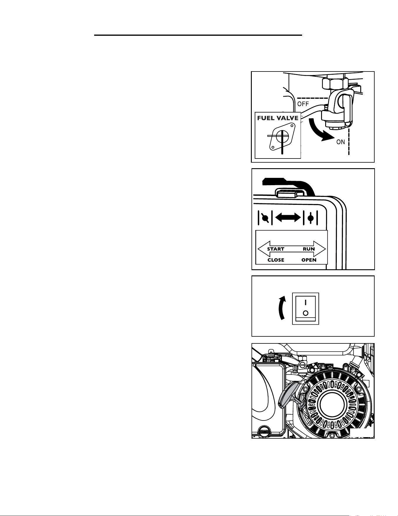
STARTING THE GENERATOR
To start the generator, perform the following steps:
1. Place the generator outside on a dry, level surface. Allow at least two
feet of clearance on all sides of the generator.
2. Check there is sufficient level of oil in the crankcase. Add oil if nec-
essary (refer to “Add/Check Oil” on page 10).
3. Check there is sufficient level of gasoline in the fuel tank. Add fuel
is necessary (refer to “Add/Check Gasoline” on page 11).
4. To maximize safety, make sure the generator is properly grounded
(Refer to “Ground the Generator” on page 11).
Before starting the generator, make sure you have read and performed the steps in the “Generator Preparation”
section of this manual. If you are unsure about how to perform any of the steps in this manual please call (800) 232-
1195 M-F 8-5 CST for customer service.
STARTING THE GENERATOR
5. Make sure all electrical devices are unplugged from the generator dur-
ing ignition. Otherwise it will be difficult for the engine to start.
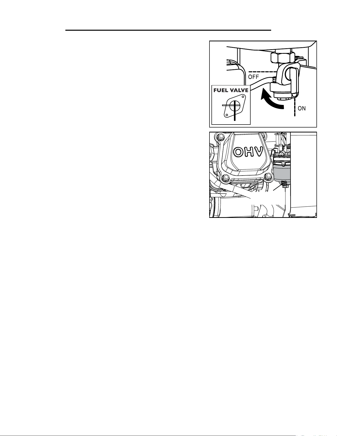
6. Turn the fuel valve to the ON position (Fig. 7).
7. Move the choke lever to the CLOSED position (Fig. 8).
8. Set the engine switch on the control panel to the ON position (Fig. 9).
9. Pull on the recoil starter handle (Fig. 10) slowly until a slight resistance
is felt, then pull quickly to start the engine. Return cord gently into the
recoil starter. Never allow the cord to snap back.
10. If engine fails to start, repeat step 9.
NOTE: After repeated failed attempts to start the engine, please consult
the troubleshooting guide before attempting again. If problems persist
please call (800) 232-1195 M-F 8-5 CST.
11. Once the engine has started, slowly return the choke lever all the way
to the OPEN position (Fig. 8).
12. Allow the engine to run for several minutes before attempting to con-
nect any electrical devices. This allows the generator to stabilize its speed
and temperature.
Fig. 10
Fig. 7
Fig. 8
Fig. 9
ON
OFF
OIL LEVEL SHUTDOWN
The generator is equipped with a low oil pressure shutoff that will automatically stop the engine when the oil level is
too low to protect the unit from damage. The oil level of the engine should be checked before each start to ensure
that the engine crankcase contains sufficient lubricant.
Choke Lever
ON
OFF
D
13

Fig. 11 - Estimated wattage requirements of common electrical devices
USING THE GENERATOR
DETERMINING ELECTRICAL DEVICES
Rated (Running) Wattage: 4500W. The rated wattage is the wattage that the generator can produce on a con-
tinuous basis. The total running wattage requirement of the electrical devices connected to the generator should not
exceed the rated wattage of the generator 4500W.
Surge Wattage: 5000W. The surge wattage is the maximum amount of power the generator can produce for an
extremely short period of time (seconds). Many electrical devices such as refrigerators require short bursts of extra
power in addition to the rated wattage listed by the device to start their motors. The surge wattage ability of the gen-
erator covers this extra power requirement.
The wattage of each electrical device should be listed on the device or in its instruction manual. If this wattage
cannot be found, calculate it by multiplying the Voltage requirement by the Amperage drawn: Watts = Volts x Am-
peres. Use the chart below only as an estimated reference. However, do not solely rely on this chart - all electronics
and appliances are built differently. These are not standard wattages across the board, only estimations. Always
check the wattage listed on the electrical device before consulting this chart.
Tool or Appliance Rated (Running) Watts Surge (Starting) Watts
Electric water heater (40 Gal) 4000 0
Hot plate 2500 0
Saw - radial arm 2000 2000
Electric stove (each element) 1500-2800 0
Saw - circular 1500 1500
Air compressor (1 HP) 1500 3000
Window air conditioner 1200 1800
Saw - miter 1200 1200
Microwave 1000 0
Well water pump 1000 1000
Saw - reciprocating 960 1040
Sump pump 800 1200
Refrigerator freezer 800 1200
Furnace blower 800 1300
Computer 800 0
Electric drill 600 900
Television 500 0
Deep freezer 500 500
Garage door opener 480 0
Stereo 400 0
Box fan 300 600
Clock radio 300 0
Security system 180 0
DVD player / VCR 100 0
Common light bulb 75 0
14
CALCULATING THE TOTAL WATTAGE
When the rated wattage requirement of each electrical device has been determined, add these numbers to find the
total rated wattage needed. If this number exceeds the rated wattage (4500W) of the generator, DO NOT connect
all these devices. Select a combination of electrical devices, which have a total rated wattage lower than or equal to
the rated wattage of the generator.
CAUTION: The generator can run at its surge wattage capacity for only a short time. Connect electri-
cal devices requiring a rated (running) wattage equal to or less than the rated wattage (4500W) of the
generator. Never connect devices requiring a rated wattage equal to the surge wattage of the generator.
This can trip the circuit protectors (circuit breakers).
CONNECTING ELECTRICAL DEVICES
1. Before connecting electrical devices, allow the generator to run for a few minutes to stabilize the speed and volt-
age output.
CAUTION: Become familiar with the markings on the control panel (Fig. 12) before connecting elec-
trical devices. Do not connect 50Hz loads to the generator.
2. Make sure that all devices are turned off. Start plugging in each electric device, from the highest wattage to the
lowest. Check the power indicator light to ensure the generator is producing power.
3. Do not overload the generator or individual panel receptacles. If an overload occurs, the power indicator light
will turn off. Unplug all electrical devices and then press the circuit breaker to reset. Check the total wattage of the
devices and reduce the load if it exceeds the capacity of the generator. Then plug the loads back in one by one.
NOTE: If the circuit breaker does not reset, wait several minutes and try again. If the power light still does not come
on, call the customer service number for further instructions.
USING THE GENERATOR
20A
Circuit Breakers
Engine
Hour Counter
Power Indication
Light
DC 12V
5-20R
(AC 120V, 20A)
120V/240V
Voltage Selector
L14-30R
(AC 120V/240V, 30A)
TT-30R RV
(AC 120V, 30A)
Engine
ON/OFF Switch
Grounding
Plug
15
Fig. 12 - Control Panel
NOTE: Do not exceed 30A on the TT-30R receptacle and do not exceed 20A on the 5-20R receptacle.
USING THE GENERATOR
STOPPING THE GENERATOR
SHUTTING OFF THE GENERATOR
1. Turn off all electrical devices and then unplug the devices from the generator. Unplugging running devices can
cause damage to the generator.
2. Turn the engine switch to the OFF position.
3. Turn the fuel valve to the OFF (horizontal) position.
4. Drain the carburetor (See “Draining the Carburetor” on Page 19).
CAUTION: Allowing gasoline to sit in the fuel tank for long periods of time can make it difficult to start
the generator in the future. Never store the generator for extended periods of time (over 2 months) with
fuel in the fuel tank. Refer to “Storing the Generator” on page 22.
WARNING: Allow the generator to cool for several minutes before touching areas that
become hot during use.
SOME NOTES ABOUT POWER CORDS
Long or thin cords can drain the power provided to an electrical device by the generator. When using such cords,
allow for a slightly higher rated wattage requirement by the electrical device. See Fig. 13 for recommended cords
based on the power requirement of the electrical device.
Device Requirements Max. Cord Length (ft) by Wire Gauge
Amps Watts (120V) #8 wire #10 wire #12 wire #14 wire #16 wire
2.5 300 NR NR NR 375 250
5 600 NR NR 300 200 125
7.5 900 NR 350 200 125 100
10 1200 NR 250 150 100 50
15 1800 NR 150 100 65 NR
*NR = Not Recommended Fig. 13 - Maximum Extension Cord Lengths by Power Requirement
16

CLEANING THE GENERATOR
Keep the generator clean to prevent improper operation or machine damage from dirt and debris. Inspect all ven-
tilation openings on the generator. These openings must be kept clean and unobstructed. If the generator becomes
dirty, use a damp cloth to wipe exterior surfaces. Use a soft bristle brush to loosen dirt and oil and use a vacuum to
pick up loose dirt. Use low pressure air (not to exceed 25 PSI) to blow away dirt.
CAUTION: Never clean the generator when it is running! Never clean with a bucket of water or a hose.
Water can get inside the working parts of the generator and cause corrosion or a short circuit.
MAINTENANCE
Proper routine maintenance of the generator will help prolong the life of the machine. Please perform mainte-
nance checks and operations according to the schedule in Figure 14.
CAUTION: Never perform maintenance operations while the generator is running. Before maintaining or servic-
ing the generator, turn OFF the generator, disconnect all devices and allow the generator to cool down.
If there are any questions about the maintenance procedures listed in this manual, please call (800) 232-1195 M-F
8-5 CST or email [email protected].
Fig. 14 - Recommended Maintenance Schedule
* Clean/change more often under dusty conditions or operating under heavy load.
Recommended
Maintenance Schedule
Each 8
hours or
daily
Every 25
hours
Every 3
months or
50 hours
Every 6
months or
100 hours
Every
year
As necessary
Engine oil
Check level x
Replace x* x* x
Air filter
Check x* x
Clean x*
Spark plug
Check/clean/
regap
x
Change x x
Fuel tank
Check level x
Drain x
Carburetor Drain x
IMPORTANT REMINDER FROM YOUR FRIENDS AT WEN:
• Drain your carburetor after every use (see page 19) to prevent it from clogging.
• Do not store the generator with fuel inside the tank for more than 2 months. The fuel will go bad.
• Run the generator for at least 15 minutes every month to maximize its lifespan. The generator
needs your attention, love and care.
17
MAINTENANCE
CHECKING/ADDING THE OIL
Check the oil level of the generator according to the Recommended
Maintenance Schedule in Fig. 14. The oil level should be checked
before each use or every 8 hours of operation. The oil capacity of
the generator engine is 33.8 fl. ounces. Add oil when the oil level is
low. For proper type and weight of oil refer to “add oil” portion of
the “Generator Preparation” section on page 10. The generator is
equipped with an automatic shutoff to protect it from running on low
oil. To check the oil level:
1. Make sure the generator is on a level surface. Do not tilt the generator to assist in filling as oil will flow into
engine areas and cause damage. Keep generator level!
2. Remove the dipstick (Fig. 15) and wipe it with a clean rag.
3. Insert the dipstick into the oil fill opening without screwing in. Remove the dipstick to check the oil mark. Add
oil if the oil mark covers less than one half of the dipstick.
4. Using a funnel or appropriate dispenser, slowly add more oil. Repeat step 2 until the oil mark reaches the top
of the dipstick (and you can see oil coming up the threads of the oil fill). Do not over fill the crankcase.
5. Reinstall dipstick and wipe clean any spill oil with a rag.
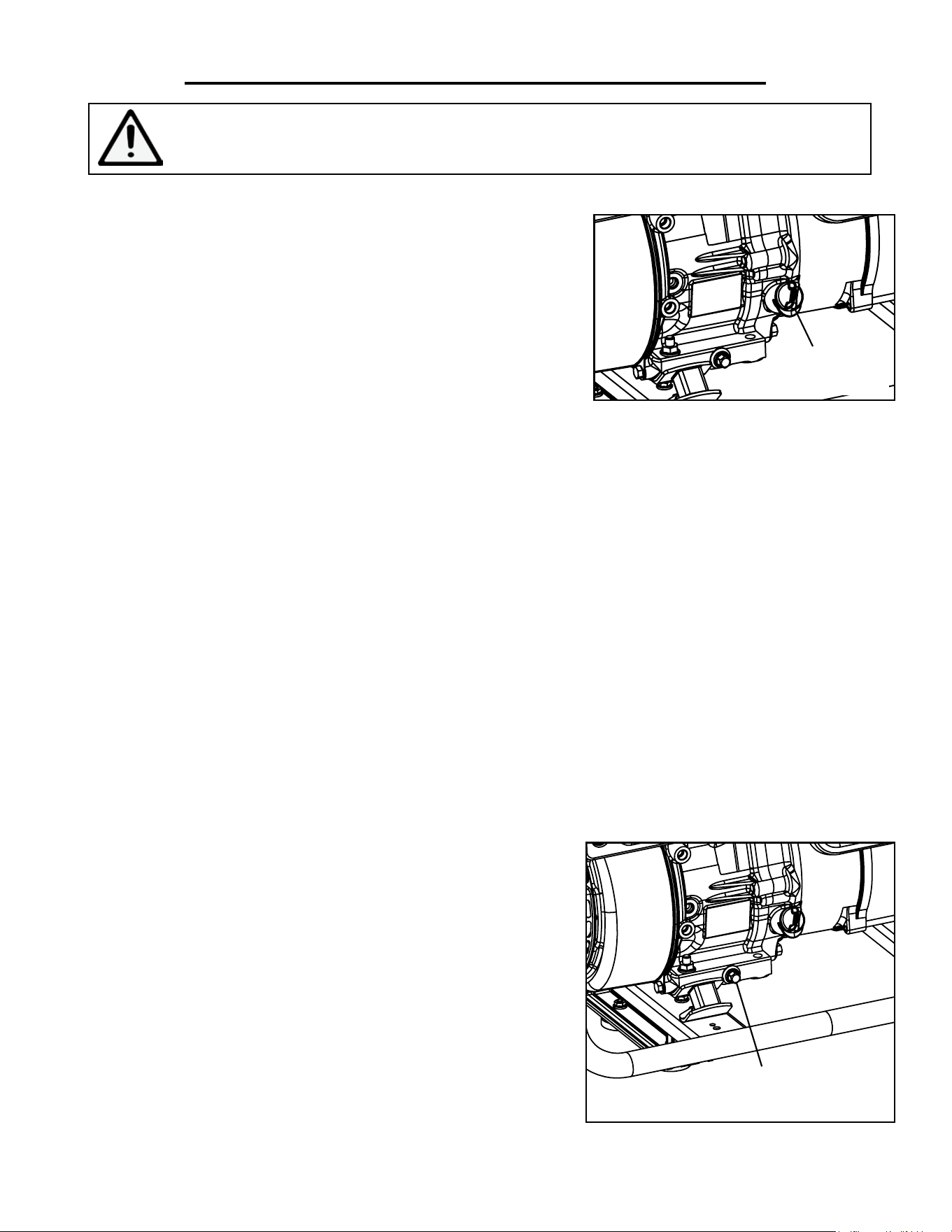
DRAINING/CHANGING THE OIL
Change the oil according to the Recommended Maintenance Schedule in Fig. 14. Change the oil more often if
operating under heavy load or high ambient temperatures. It is also necessary to drain the oil from the crankcase
if it has become contaminated with water or dirt. Changing the oil when the engine is warm allows for complete
drainage. Drain the oil from the generator according to the following steps.
Fig. 16
Oil Drain
Plug
Oil Dipstick
WARNING: Make sure the generator is shut off before performing any inspection or
maintenance procedures.
1. Place generator on elevated platform such as table or desk. Pre-
pare a container underneath the oil drain plug next to the oil dipstick
to catch the oil as it drains.
2. Unscrew oil drain plug (Fig. 16) and allow the oil to drain from the
engine completely.
3. Reinstall the oil drain plug and tighten it securely. Wipe clean any
oil spillage.
NOTE: NEVER dispose of used motor oil in the trash or down a
drain. Please call a local recycling center or auto garage to arrange
proper oil disposal.
Fig. 15
18
MAINTENANCE
Carburetor
Drain Screw
Spark Plug
Boot
DRAINING THE CARBURETOR
Draining the carburetor is recommended after every use to prevent
the fuel from clogging up the carburetor. The carburetor can be ac-
cessed from the backside of the generator between the engine and
the air filter (Fig. 17).
1. Turn the fuel valve to OFF position to prevent gasoline from
draining from the fuel tank.
2. Open up the carburetor drain screw (Fig. 17) with a screwdriver
and drain out any gasoline that has built up inside.
3. Once the fuel has drained, close the drain plug with the screw-
driver. NOTE: Make sure to drain your carburetor before storing
the generator for long periods of time.
Fig. 17
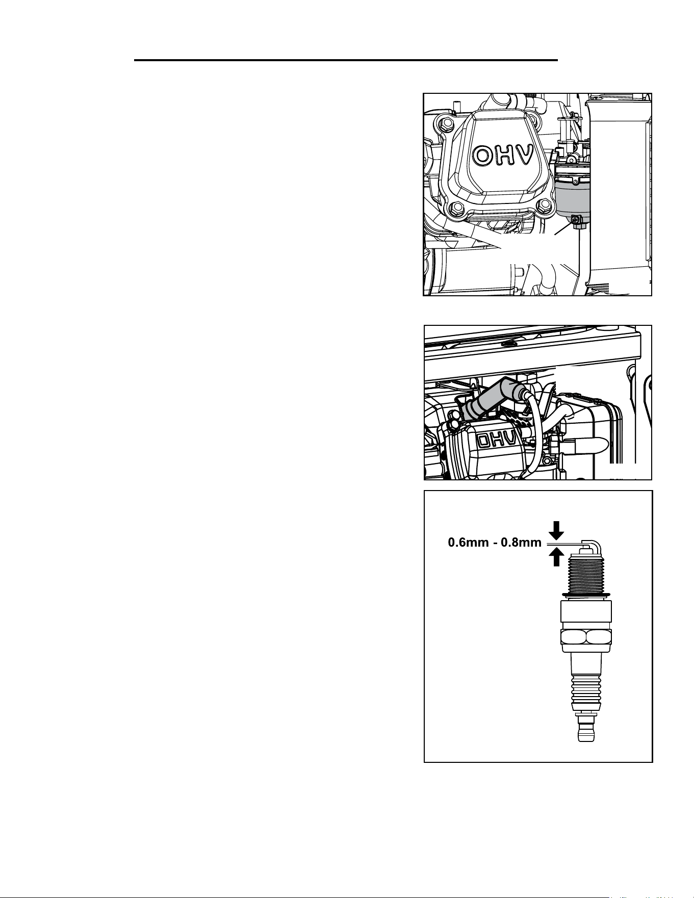
SPARK PLUG MAINTENANCE
The spark plug is important for proper engine operation. A good
spark plug should be intact, free of deposits, and properly gapped.
Refer to Recommended Maintenance Schedule in Figure 14 for
maintaining the spark plug. To inspect the spark plug:
1. Clean and remove the spark plug boot (Fig. 18). Be careful not to
tear any insulation or wire.
2. Use the spark plug wrench provided to unscrew and remove the
spark plug from the engine.
3. Visually inspect the spark plug for cracks or excessive electrode
wear. If the electrodes are worn, burned or porcelain is cracked,
replace with a F6TC (NGK BP6ES) spark plug (Part No. 56500-138),
available at wenproducts.com
4. If re-using the spark plug, use a wire brush to clean any dirt from
around the spark plug base then re-gap the spark plug.
5. Measure the plug gap with a wire gauge (Fig. 19). The gap should
be 0.6 to 0.8 mm (0.024 to 0.031 in). Carefully adjust the gap if neces-
sary.
6. Screw the spark plug back into the spark plug hole by hand. After
the spark plug is properly seated, use the provided spark plug wrench
to tighten it.
Fig. 18
Fig. 19
NOTE: The spark plug torque is 9 - 12 n.m ( 7 - 8 ft.lb). The recommended tightening of spark plug is ½ to ¾ of
a turn after spark plug gasket contacts spark plug hole. DO NOT over-tighten the spark plug.
7. Reinstall the spark plug boot.
19
MAINTENANCE
SPARK ARRESTER MAINTENANCE
It is recommended to inspect and clean the spark arrester every
200 hours of operation.
1. The spark arrester is located outside the muffler, which gets very
hot during operation. Allow the engine to cool completely before
servicing the spark arrester.
2. Remove the two screws holding the cover plate that retains the
end of the spark arrester to the muffler.
3. Remove the spark arrester screen.
4. Carefully clean and remove the carbon deposits from the spark
arrester screen with a wire brush. Replace the spark arrester if it is
damaged.
5. Reinstall the spark arrester in the muffler and secure it in place
with the screws.
Spark
Arrester
Cover Bolt
Air Filter
Cover
Air Filter
Element
AIR FILTER MAINTENANCE
Routine maintenance of the air filter helps maintain proper
airflow to the carburetor. Occasionally check that the air filter is
free of excessive dirt. The air filter should be checked every 50
hours of use. Refer to Recommended Maintenance Schedule in
Fig. 14.
1. Unscrew the cover bolt (Fig. 20) and remove the air filter
cover. Remove the air filter element from the casing.
2. Check and clean the foam air filter element as described in
step 3 below. Good elements can be washed, dried and reused.
If the element is damaged, replace it with a new one.
3. Wash the air filter element in warm soapy water. Squeeze it
thoroughly dry in a clean cloth. Saturate the element in clean
engine oil and squeeze off excess oil in a clean abosrbent cloth.
A small amount of oil in the element is normal and necessary for
Fig. 20
Fig. 21
the engine to work properly.
4. Reinstall the air filter element. Close the cover and secure it with the cover bolt.
CAUTION: Running the engine with dirty, damaged or missing air filter element result in possible danger and
cause the engine to wear out prematurely.
20
STORAGE & TRANSPORT
DRAINING THE FUEL TANK
Drain the fuel tank every year and before storing the generator for
longer than one to two months. Refer to Recommended Mainte-
nance Schedule in Figure 14. To drain the fuel tank:
1. Turn the fuel valve to the OFF position (Fig. 22).
2. Prepare a suitable container under the carburetor for catching the
drained fuel.
3. Open up the carburetor drain screw (Fig. 23) with a screwdriver.
Gasoline will start to drain from the carburetor.
4. Open the fuel valve by turning it to the ON position to let the fuel
drain completely from the fuel tank.
5. Once the fuel has drained, shut off the fuel valve and close the
carburetor drain screw with the screwdriver.
6. Store the emptied gasoline in a suitable place. DO NOT store
flammable materials near the gasoline.
CAUTION: Do not store the emptied fuel for more than 3 months.
Fig. 23
Fig. 22
Carburetor
Drain Screw
ON
OFF
21

TRANSPORTING THE GENERATOR
• Tighten the fuel cap and turn the fuel valve to OFF position.
• Drain the fuel tank if possible (see Draining the Fuel Tank).
• Keep the generator upright. Never place the generator on its side or upside down. Doing so will make it difficult
to start.
PRODUCT DISPOSAL
Used generators should not be disposed of together with household waste. This product contains electrical or elec-
tronic components that should be recycled. Please take this product to your local recycling facility for responsible
disposal and to minimize its environmental impact.
DO NOT dispose of used oil or fuel in the trash or down a drain. Please contact your local recycling center or
auto garage to arrange proper oil disposal.
STORAGE & TRANSPORT
STORING THE GENERATOR
Shut off the generator and allow the unit to cool to room temperature before storage. Never place any type of stor-
age cover on the generator while it is still hot. Do not obstruct any ventilation openings. Store the generator and fuel
in a cool and dry location, away from sources of heat, open flames, sparks or pilot lights. Follow the procedures
below for properly storing your generator.
For Short Periods (30 to 60 Days):
• Drain the carburetor (see page 19).
• Gasoline stored over 30 days can go bad and damage fuel system components. Add fuel stabilizer, following
the suggested portions and instructions of your preferred stabilizer. Run the engine for 2 to 3 minutes, allow-
ing the fuel stabilizer to mix with the gasoline and circulate through the carburetor, and then top off with fuel.
NOTE: Filling the fuel tank full reduces the amount of air in the tank and helps fight deterioration of fuel.
For Extended Periods (Over 60 Days):
• Drain the carburetor (see page 19).
• Drain the fuel tank (see Draining the Fuel Tank on page 21). NEVER store with fuel in the tank for more than
two months.
• Change engine oil (see Draining the Oil on page 18).
IMPORTANT: Run the generator ONCE A MONTH for 15 minutes. This is necessary for prolonging
the lifetime of your generator and ensure that the generator can function properly for your next opera-
tion. Afterwards, shut off and drain the carburetor. Store the generator with a dry carburetor.
22

Rated Wattage 4500 Watts
Surge Wattage 5000 Watts
Phase Single
Frequency 60Hz
Rated Voltage AC: 120V/240V, DC: 12V
Rated Amperage AC: 40A/20A, DC: 9A
Dimensions
Length: 26.2 in.
Width: 17.7 in.
Height: 18.7 in.
Weight 121 lbs
ENGINE
Engine Type 4 stroke, OHV, single cylinder with forced air cooling system
Engine Displacement 272cc
Engine Speed 3600 RPM
Fuel Tank Capacity 3.4 gallons (87 octane minimum)
Oil Capacity 33.8 fl.oz.
Lubrication System Splash lubrication
Half-Load Run Time 7.5 hours
Noise Rating 68 dB at 22 feet
Spark Plug Type F6TC/ NGK BP6ES
Spark Plug Gap 0.6 - 0.8 mm (0.024 - 0.031 in)
Spark Plug Torque 9 - 12 n.m ( 7 - 8 ft.lb )
Intake Valve Gap 0.1 - 0.15mm (SAE 0.00394 - 0.00591)
Exhaust Valve Gap 0.15 - 0.20 mm (SAE 0.00591 - 0.00787)
SPECIFICATIONS
23
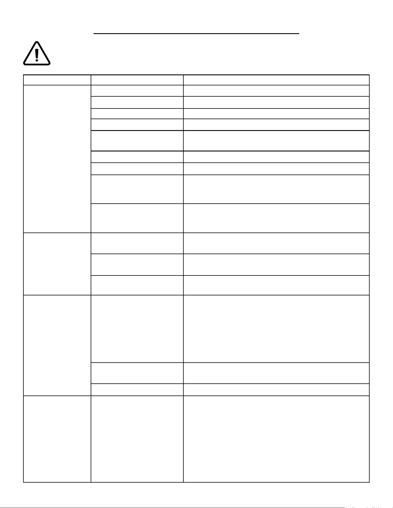
PROBLEM POSSIBLE CAUSE SOLUTION
Engine will not start.
Engine switch is set to OFF. Set engine switch to ON.
Fuel valve is turned to OFF. Turn fuel valve to ON.
Choke is open. Close the choke.
Engine is out of fuel. Add fuel (see page 11).
Engine is filled with con-
taminated or old fuel.
Drain the fuel in the tank (see page 21). Fill with fresh fuel
(see page 11).
Spark plug is dirty. Clean the spark plug (see page 19).
Spark plug is broken. Replace spark plug (see page 19).
Oil level is low.
Add or replace oil (see page 18). This generator is
equipped with a low oil sensor. The engine will not start
unless the oil level is sufficient.
Carburetor is air locked.
Shut off the fuel valve. Remove the nut from the bottom of
the carburetor. Take off the carburetor to allow it to reset.
Place the carburetor back and reinstall the nut.
Engine runs but
there is no electrical
output.
Circuit breaker has been
tripped due to overload.
Disconnect all the loads. Wait for two minutes and push
the circuit breaker to the ON position to reset it.
Bad connecting cords/wires.
Check the power cords and extension cords. Do not use if
any cord is damaged. Replace damaged cords immediately.
Bad electrical device con-
nected to the generator.
Try connecting a different device.
Generator runs but
does not support
all electrical devices
connected.
Generator is overloaded.
Perform these steps:
1. Turn off all electrical devices.
2. Unplug all electrical devices.
3. Turn off generator.
4. Wait several minutes.
5. Restart generator.
6. Try connecting few electrical loads to the generator.
Short circuit in one of the
devices.
Try disconnecting any faulty or short-circuited electrical
loads.
The air filter is dirty. Clean or replace the air filter element (see page 20).
Engine is “Hunting”
during Operation
(Engine RPM is
fluctuating).
1. The fuel isn’t running
through the fuel valve.
2. The air filter is clogged.
3. The Muffler or spark ar-
rester is blocked
4. There is gunk in the car-
buretor preventing the fuel/
air to be consistent.
Turn off the generator and wait for it to cool down. Per-
form the following steps:
1. Check if the fuel is properly and consistently going
through the fuel valve
2. Check for any blockage in the air filter. Check and clean
the air filter as necessary (see page 20).
3. Check if the spark arrester is blocked. Clean with metal
brush as necessary (see page 20).
4. Use “Gunk remover” spray on the carburator jets.
TROUBLESHOOTING
WARNING: Stop using the generator immediately if any of the following problems occur or risk serious
personal injury. If you have any questions, please contact our customer service at (800) 232-1195, M-F
8-5 CST or email us at [email protected].
24
25
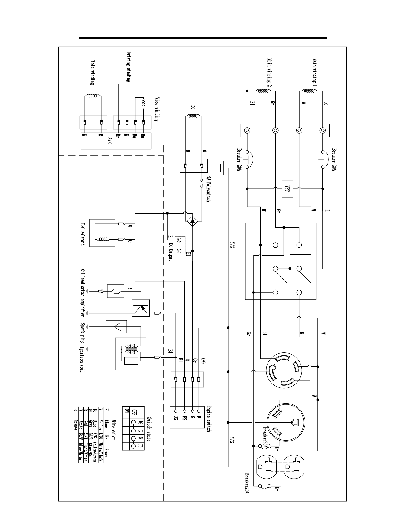
WIRING DIAGRAM
26
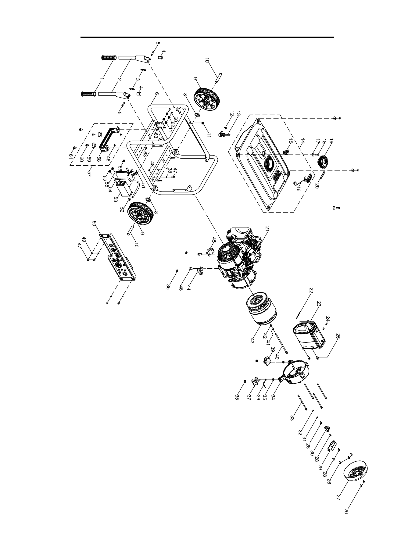
EXPLODED VIEW AND PARTS LIST
GENERATOR:

EXPLODED VIEW AND PARTS LIST
No. Part No. Description Qty.
1
56500-001
Handle Jacket 2
2 Push Handle 2
4 Handle Plug 2
3 56500-004 Cotter Pin (Handle) 2
5 56500-005 Handle Axle, φ10×40 2
6 56500-006 Frame Assembly 1
7 56500-007 Cotter Pin (Wheel) 2
8 56500-008 Washer, φ17.5xφ30x3 2
9 56500-008 Wheel 2
10 56500-009 Wheel Axle, φ16×85 2
11 56500-010 Damping Pad 3
12 56500-011 Clamp 1
13 56500-012 Fuel Switch 1
14 56500-013 Fuel Tank 1
15 56500-014 Pressure Relief Valve 1
16 56500-015 Fuel Gauge 1
17 56500-016 Washer, φ6.5×2×φ25 4
18 56500-017 Bolt, M6×25 4
19 56500-018 Fuel Cap 1
20 56500-019 Fuel Gauge Label 1
21 56500-020 Engine 1
22 56500-023 Muer Gasket 1
23
56500-024 Muer 1
56500-024.1 Spark Arrester 1
24 56500-025 Nut, M8 2
25 56500-026 Bolt, M8×16 2
26 56500-027 Bolt, M5×14 5
27 56500-028 End Cover 1
28 56500-029 Bolt, M5×18 3
29 56500-030 Voltage Regulator 1
30 56500-031 Carbon Brush Set 1
31 56500-032 Washer A, φ6 1
32 56500-033 Washer B, φ5 1
33 56500-034 Bolt, M6×150 4
34 56500-035 Rear Bracket 1
35 56500-036 Nut, M8 8
No. Part No. Description Qty.
36 56500-037 Reinforcement Support 1
37 56500-038
Damping Bracket (Right
Rear)
2
38 56500-1038 Washer B, φ6 1
39 56500-039
Damping Bracket (Left
Rear)
2
40 56500-040 Bolt, M10-1.25x225 1
41 56500-041 Washer A, φ10 1
42 56500-042 Washer B, φ10 1
43 56500-043 Alternator 1
44 56500-1044
Damping Bracket (Right
Front)
1
45 56500-1045
Damping Bracket (Left
Front)
1
46 56500-1046 Flange Bolt M8x16 2
47 56500-1047 Bolt M6x12 5
48 56500-044 Nut, M6 2
49 56500-045 Washer, M6 2
50 56500-046 Control Panel Assembly 1
51 56500-047 Clamp A 2
52 56500-052 Clamp A, Carbon Tank 3
53 56500-049 Carbon Tank 1
54 56500-050 Tube A, Carbon Tank 1
55 56500-051 Tube B, Carbon Tank 1
56 56500-053 Clamp B, Carbon Tank 2
57 56500-057 Support Base Assembly 1
58 56500-058 Support Base 1
59 56500-059
Damping Pad,
Support Base
2
60 56500-054 Bolt, M6x18 2
61 56500-060 Bolt, M8x16 2
62 56500-055 Bushing 2
63 56500-056 Flanged Lock Nut, M8 2
27
28
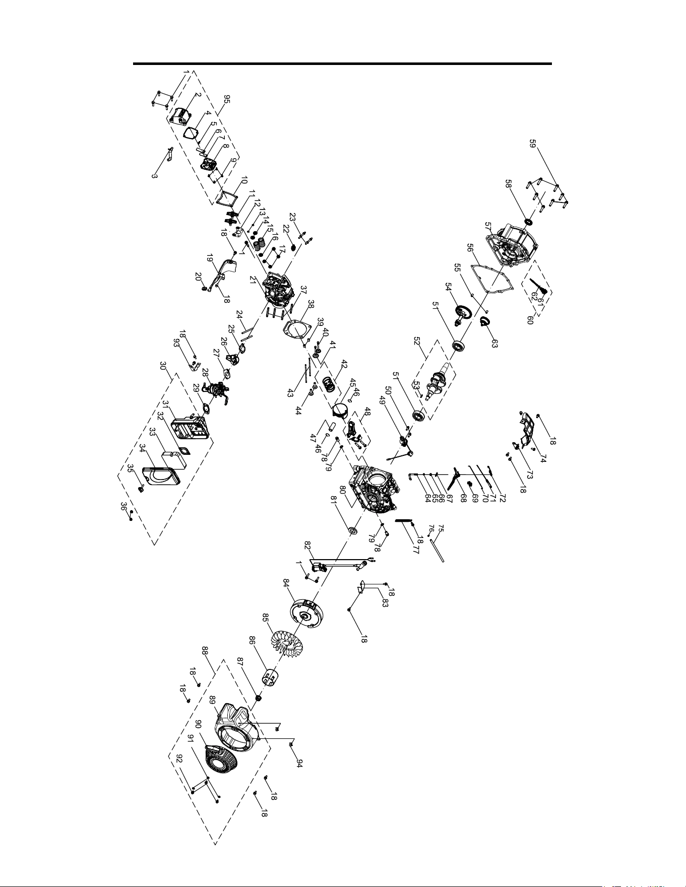
EXPLODED VIEW AND PARTS LIST
ENGINE:

EXPLODED VIEW AND PARTS LIST
No. Part No. Description Qty.
1 56500-017 Bolt, M6×25 7
2 56500-102 Valve Cover 1
3 56500-103 Breather Hose 1
4 56500-104 Gasket, Valve Cover 1
5 56500-105 Rivet, M3×8 2
6 56500-106 Breather Plate 1
7 56500-107 Breather Valve 1
8 56500-108 Inner Cover, Valve Cover 1
9 56500-109 Screw, M5×12 4
10 56500-110 Gasket, Valve Cover 1
11 56500-111 Rocker Arm Assembly 2
12 56500-112 Rocker Arm Base 1
13 56500-113 Valve Locker 4
14 56500-114 Valve Spring Seat 2
15 56500-115 Valve Spring 2
16 56500-116 Intake Valve Seal 1
N. P. 56500-116.1 Exhaust Valve Seal 1
17 56500-117 Nut, M8 4
18 56500-022 Bolt, M6×12 13
19 56500-119 Shroud 1
20 56500-1120 Shroud Mounting Clasp 1
21 56500-122 Cylinder Head 1
22 56500-123 Spark Plug F6TC (NGK BP6ES) 1
23 56500-124 Stud 1
24 56500-125 Stud, M6×90 2
25 56500-126 Gasket, Carburetor Insulator 1
26 56500-127 Insulator 1
27 56500-128 Gasket, Carburetor 1
28 56500-129 Carburetor 1
29 56500-130 Gasket Carburetor 1
30 56500-131 Air Filter Assembly 1
31 56500-132 Air Filter Base Assembly 1
32 56500-133 Air Filter Bae 1
33 56500-134 Air Filter Element 1
34 56500-135 Air Filter Cover 1
35 56500-136 Bolt 1
36 56500-137 Nut, M6 2
37 56500-138 Stud, M8×60 4
38 56500-139 Gasket, Cylinder Head 1
39 56500-140 Pin,φ10×14 2
40 56500-141 Intake Valve 2
41 56500-142 Exhaust Valve 1
42 56500-143 Piston Ring Set 1
43 56500-144 Push Rod 2
44 56500-145 Tappet 1
45 56500-146 Piston 1
46 56500-147 Circlip 2
47 56500-148 Piston Pin 1
48 56500-149 Connecting Rod Assembly 1
No. Part No. Description Qty.
49 56500-150 Oil Sensor 1
50 56500-151 Bolt, M6×18 2
51 56500-1151 Crankshaft Bearing 2
52 56500-152 Crankshaft Assembly 1
53 56500-153 Woodru Key 1
54 56500-155 Camshaft 1
55 56500-156 Pin,φ8×14 2
56 56500-157 Gasket, Crankcase 1
57 56500-158 Crankcase Cover 1
58 56500-159 Oil Seal, φ25×φ41.25×6 1
59 56500-160 Bolt, M8x35 1
60 56500-161 Dipstick Assembly 1
61 56500-163 Dipstick 1
62 56500-162 O-Ring, φ15.8×2.5 1
63 56500-164 Governor Gear 1
64 56500-165 Governor Gear Shaft 1
65 56500-166 O-Ring, φ5.2x1.9 1
66 56500-167 Oil Seal, φ6xφ11x4 1
67 56500-168 Cotter Pin 1
68 56500-169 Governor Lever 1
69 56500-170 Choke Linkage Lock Clamp 1
70 56500-171 Throttle Linkage 1
71 56500-172 Idle Spring 1
72 56500-173 Governor Spring 1
73 56500-174 Throttle Adjust Bracket Assembly 1
74 56500-175 Governor Gear Bracket Assembly 1
75 56500-176 Fuel Hose, φ4×φ10×126 1
76 56500-177 Clamp, Fuel Hose 1
77 56500-178 Clip 1
78 56500-179 Drainage Bolt 1
79 56500-180 Washer, φ10xφ16x1.5 1
80 56500-181 Crankcase 1
81 56500-182 Oil Seal, φ27×φ47×7 1
82 56500-183 Ignition Module 1
83 56500-184 Wire Board 1
84 56500-185 Flywheel 1
85 56500-186 Cooling Fan 1
86 56500-187 Starter Cup 1
87 56500-188 Nut, M14×1.5 1
88 56500-189 Recoil Starter Assembly 1
89 56500-190 Blower Housing 1
90 56500-191 Recoil Starter 1
91 56500-192 Washer, φ6 3
92 56500-193 Bolt, M6×10 3
93 56500-1193 Air Filter Bracket 1
94 56500-1194 Clip 1
95
56500-
1195ASM
Valve Cover Assembly 1
29

WARRANTY STATEMENT
Remember to save the receipt and to accurately fill out and mail the product registration card. Proof of purchase
is required for all warranty work.
WEN® Generators are under warranty to be free from defects in materials and workmanship for a period of two
(2) years from date of original purchase. Generators used for Commercial or Rental use have a warranty period of
90 days from date of original purchase. Keep purchase receipt and mail in the product registration card for proof
of purchase.
WEN® will repair or replace, at its discretion, any part that is proven to be defective in materials or workman-
ship under normal use during the two (2) years warranty period. Warranty repairs or replacements will be made
without charge for parts or labor. Parts replaced during warranty repairs will be considered as part of the original
product and will have the same warranty period as the original product.
To exercise the warranty, DO NOT RETURN TO RETAILER. Instead, call the toll free Customer Service
number at (800) 232-1195 and you will be instructed on where to take the generator for warranty service. Take
the generator and proof of purchase (the receipt) to the repair facility recommended by the Customer Service
Representative. To make a claim under this Limited Warranty, you must make sure to keep a copy of your proof
of purchase that clearly defines the Date of Purchase (month and year) and the Place of Purchase. Place of pur-
chase must be a direct vendor of Great Lakes Technologies, LLC. Third party vendors such as garage sales, pawn
shops, resale shops, or any other secondhand merchant void the warranty included with this product. Contact
[email protected] or 1-800-232-1195 to make arrangements for repairs and transportation.
When returning a product for warranty service, the shipping charges must be prepaid by the purchaser. The prod-
uct must be shipped in its original container (or an equivalent), properly packed to withstand the hazards of ship-
ment. The product must be fully insured with a copy of the warranty card and/or the proof of purchase enclosed.
There must also be a description of the problem in order to help our repairs department diagnose and fix the
issue. Repairs will be made and the product will be returned and shipped back to the purchaser at no charge.
THIS LIMITED WARRANTY DOES NOT APPLY TO ACCESSORY ITEMS THAT WEAR OUT FROM
REGULAR USAGE OVER TIME INCLUDING BELTS, BRUSHES, BLADES, ETC.
The warranty does not extend to generators damaged or affected by fuel contamination, accidents, neglect, mis-
use, unauthorized alterations, use in an application for which the product was not designed and any other modifi-
cations or abuse. Labor for warranty parts is only covered for the contiguous United States (48 states).
WEN® is not liable for any indirect, incidental or consequential damages from the sale or use of this product.
Any implied warranties are limited to two (2) years as stated in this written limited warranty. Some states do not al-
low the exclusion or limitation of incidental or consequential damages. Some states do not allow limitation on the
length of an implied warranty. This warranty gives you specific legal rights, and you may have other rights that vary
from state to state.
30


THANKS FOR
REMEMBERING