
16" 40V MAX* Lithium-Ion Cordless Mower CLMB4016K
Read all safety rules and instructions carefully before operating this tool.
Distributed By Cleva North America 601 Regent Park Court Greenville, SC 29607 (866)-384-8432
* Tension batterie de la charge de travail initiale maximale (mesurée sans charge de travail)
est de 40 volts.
Tension nominale est de 36 volts
* Maximum initial battery workload voltage (measured without a workload) is 40 volts.
Nominal voltage is 36 volts
Lisez toutes les règles et consignes de sécurité avant d'utiliser cette tondeuse.
Distribuée par Cleva North America 601 Regency Park Court, Greenville, SC 29607 (866)-384-8432
MNL_CLMB4016K_V1
EN p. 2
Operators Manual / Guide d'Utilisation
Tondeuse Sans Fil CLMB4016K 40V MAX* 406 mm (16 po)
FR p. 32

2
CONTENTS
SPECIFICATIONS
INTRODUCTION
GENERAL SAFETY RULES
SPECIFIC SAFETY RULES
SYMBOLS
FEATURES
ASSEMBLY
OPERATION
BATTERY CHARGER
MAINTENANCE
ENVIRONMENTAL SAFE BATTERY DISPOSAL
TROUBLESHOOTING
WARRANTY
EXPLODED VIEW / PARTS LIST
NOTES
2
2
3
3-5
6-8
9-10
11-13
13-19
20-21
21-22
22-26
26
27
28
29-30
31
TABLE OF CONTENTS
SPECIFICATIONS
40V CORDLESS MOWER
Battery Type 40V MAX* Lithium-Ion
Charger Time 1.5 H
No-load Speed 3500 r/min
Cutting Width 16 Inch (40 cm)
Height Adjustments 6 Position (1”-3”) (25-75mm)
Functions 2-in-1: Mulch, Rear Bag
Wheel Size 6.5" (Front) / 10" (Rear)
Unit Weight 40.8 Lbs (18.5Kg)
* Maximum initial battery workload voltage (measured without a workload) is 40 volts.
Nominal voltage is 36 volts

GENERAL SAFETY RULES
3
INTRODUCTION
WARNING
This product has many features for making its use more pleasant and enjoyable.
Safety,performance, and dependability have been given top priority in the design of this product
making it easy to maintain and operate.
This symbol indicates important safety instructions. If these instructions are not
followed, it could endanger the personal safety and/or property of the operator
and others. Read and understand all instructions in this manual before attempting
to operate the mower. Failure to comply with these instructions may result in
personal injury.
DANGER
This mower was built to be operated according to the rules for safe operation
that are contained in this manual. As with any type of power equipment,
carelessness or error on the part of the operator can result in serious injury.
This mower is capable of amputating body parts and throwing objects. Failure
to observe the following safety rules could result in serious injury or death.
WARNING
Basic safety precautions should always be followed when using electric lawn
mowers, in order to reduce the risk of fire, electric shock, and personal injury.
WARNING
Use of this mower should be restricted to individuals who have read and
understoood and will follow the warnings and instructions that are printed in this
manual and on the mower.

4
GENERAL SAFETY RULES
• Carefully read all instructions on the mower and in the manual before attempting to assemble
and operate the mower. Keep this manual in a safe place for future reference, and consult it
regularly.
• Do not use the lawn mower in damp or wet conditions or operate in the rain.
• Become familiar with all controls and their proper operation. Know how to stop the mower and
how to disengage the power in an emergency.
• In order to avoid contact with the blade or injury caused by a thrown object, stay in the
operating zone behind the handles, and keep children and bystanders at least 50’ (15 m) away
from the mower while it is in operation. Stop the motor immediately if someone enters the
mowing area.
• Thoroughly inspect the area where the mower is to be used. Remove all stones, sticks, wire,
bones, toys, and other objects that could be tripped over or thrown by the blade. Thrown
objects can cause serious personal injury.
• Plan your mowing pattern in such a way as to avoid discharging material toward roads,
sidewalks, bystanders, etc. Do not discharge material against a wall or obstruction. Doing so
may cause the discharged material to ricochet back toward the operator.
• Always wear proper eye protection in order to protect your eyes while operating or performing
any adjustment or repair. Thrown objects that ricochet can cause serious eye injury.
• Always wear safety glasses with side shields.Everyday glasses have only impact resistant lenses.
They are NOT safety glasses. Following this rule will reduce the risk of eye injury.Use face mask
if operation is dusty.
Wear safety glasses or goggles that aremarked to comply with ANSI Z87.1 standard when
operatiing this product.
• Always wear a face mask or a dust mask when operating the mower in a dusty environment.
• Dress properly. Do not wear loose clothing or jewellery that can get caught in moving parts.
The wearing of protective gloves and safety footwear is recommended.
• Many injuries occur as a result of the mower being pulled over the operator’s foot during a
fall caused by slipping or tripping. Do not operate this mower in bare feet, or while wearing
sandals or lightweight (e.g., canvas) shoes. Do not hold on to the mower if you are falling.
Release the handle immediately.
• Never pull the mower back toward you while you are walking. If you must back the mower
away from a wall or an obstruction, first look down and behind in order to avoid tripping, and
then follow these steps:
• Step back from the mower in order to fully extend your arms.
• Be sure that you are well balanced.
• Pull the mower back slowly.
• Do not use the mower for any job except that for which it is intended. Do not force the mower.
• Do not operate the mower while under the influence of alcohol or drugs.
• Stay Alert: Do not operate the mower when you are tired. Pay attention to what you are doing.
Use common sense.
• Do not put hands or feet near rotating parts or under the cutting deck. Contact with the blade
can amputate hands and feet.
• Keep hands and feet away from cutting area.

• Do not attempt to adjust the wheels or the cutting height while the motor is running.
• Avoid dangerous environments. Do not operate the mower in the rain or in wet or damp grass.
• Mow only in daylight or in good artificial light. Do not rush a mowing job.
• Stop the blade when crossing gravel driveways, walkways, or roads.
• If the mower starts to vibrate excessively, stop the motor and check for the cause immediately.
Vibration is generally a warning of trouble.
• Stop the motor and wait until the blade comes to a complete stop before removing the collection
bag or unclogging the chute. The cutting blade will continue to rotate for a few seconds
after the motor is shut off. Do not place any part of your body in the blade area until you are
sure that the blade has stopped rotating.
• Never operate mower without a proper trail shield, discharge cover, collection bag, switch
control, or other safety device in place and in working order. Do not operate the mower with
damaged safety devices. Doing so can result in injury.
CHILD SAFETY
Tragic accidents can occur if the operator is not aware of the presence of children.
• Keep children out of the mowing area and under the watchful care of a responsible adult.
• Do not allow children under the age of 14 to operate this mower. Children who are 14 years
of age and older must read and understand the operating instructions and safety rules in this
manual, and must be trained and supervised by a parent.
• Stay alert, and turn the mower off if a child or any other person enters the mowing area.
• Look behind and down for small children before and while moving backwards.
• Use extreme care when approaching blind corners, doorways, shrubs, trees, or other objects
that may obscure your view of a child who may run into the path of the mower.
CAUTION
USE ONLY LAWNMASTER APPROVED REPLACEMENT BATTERIES, OTHER BATTERIES
MAY CAUSE INJURY OR DAMAGE TO THE MOWER.
Use with LAWNMASTER 40V Lithium-lon battery.
5
GENERAL SAFETY RULES

BATTERY SAFETY RULES
• Battery tools do not have to be plugged into an electrical outlet; therefore, they are always in
operating condition. Be aware of possible hazards when not using your battery tool or when
changing accessories. Following this rule will reduce the risk of electric shock, fire, or serious
personal injury.
• Do not place battery tools or their batteries near fire or heat. This will reduce the risk of
explosion and possibly injury.
• Do not crush, drop or damage battery pack. Do not use a battery pack or charger that has
been dropped or received a sharp blow. A damaged battery is subject to explosion. Properly
dispose of a dropped or damaged battery immediately.
• Batteries can explode in the presence of a source of ignition, such as a pilot light. To reduce
the risk of serious personal injury, never use any cordless product in the presence of open
flame. An exploded battery can propel debris and chemicals. If exposed, flush with water
immediately.
• Do not charge battery tool in a damp or wet location. Following this rule will reduce the risk of
electric shock.
• For best results, your battery tool should be charged in a location where the temperature is
more than 45°F but less than 104°F. To reduce the risk of serious personal injury, do not store
outside or in vehicles.
• Under extreme usage or temperature conditions, battery leakage may occur. If liquid comes
in contact with your skin, wash immediately with soap and water. If liquid gets into your eyes,
flush them with clean water for at least 10 minutes, then seek immediate medical attention.
Following this rule will reduce the risk of serious personal injury.
• When battery pack is not in use, keep it away from other metal objects like: paper clips, coins,
keys, nails, screws, or other small metal objects that can make a connection from one terminal
to another. Shorting the battery terminals together may cause sparks, burns, or a fire.
• Always remove battery pack from your tool when you are assembling parts, making
adjustments, cleaning, or when not in use. Removing battery pack will prevent accidental
starting that could cause serious personal injury.
• Always remove battery pack before storing the device. When battery becomes fully charged,
unplug the charger from the power supply and remove the battery pack from the charger.
• Always wear eye protection with side shields marked to comply with ANSI Z87.1, along with
hearing protection. Failure to do so could result in objects being thrown into your eyes and
other possible serious injuries.
• Keep battery pack dry, clean, and free from oil and grease. Always use a clean cloth when
cleaning. Never use brake fluids, gasoline, petroleum-based products, or any solvents to
clean battery pack.
6
SPECIFIC SAFETY RULES

7
SPECIFIC SAFETY RULES
BATTERY & CHARGER
CAUTION
USE ONLY LAWNMASTER APPROVED REPLACEMENT BATTERIES, OTHER BATTERIES MAY
CAUSE INJURY OR DAMAGE TO THE MOWER. Use with LAWNMASTER 40V Lithium-lon battery.
Ensure that the device is switched off before inserting the battery. Inserting a battery into a
power tool that is switched on may result in accidents.
Recharge the batteries indoors only because the battery charger is designed for indoor use only.
To reduce the electric shock hazard, unplug the battery charger from the mains before cleaning
the charger.
Do not subject the battery to strong sunlight over long periods and do not leave it on a heater.
Heat damages the battery and there is a risk of explosion.
Allow a hot battery to cool before charging.
Do not open up the battery and avoid mechanical damage to the battery. Risk of short circuit and
fumes may be emitted that irritate the respiratory tract. Ensure fresh air and seek medical assistance
in the event of discomfort.
Do not use non-rechargeable batteries!
The device must not be used by people (including children) with limited physical, sensory or mental
faculties or who lack the necessary experience and/or knowledge - other than they are supervised
by a person responsible for safety or are being instructed to operate the appliance by such a person.
Children must be supervised in order to ensure that they do not play with the equipment.
To charge the battery, use only the charger supplied.
Risk of fire and explosion. This ensures that
the safety of the device is maintained.
Before each use, check the charger,cable and plug and have them repaired by qualified
professionals and only with original parts.
Do not use a defective charger and do not open it up
yourself. This ensures that the safety of the device is maintained.
Connect the charger only to a socket with an earth.
Ensure that the mains voltage matches
specifications on the charger rating plate. Risk of electric shock.
Disconnect the charger from the mains before closing or opening connection to the battery /
power tool /device.
keep the charger clean and away from wet and rain. Do not use the charger outdoors.
Dirt and
the entry of water increase the risk of electric shock.
Operate the charger only with the appropriate original batteries.
Charging other batteries may
result in injuries and risk of fire.
Avoid mechanical damage to the charger.
This can result in internal short circuits.

8
SPECIFIC SAFETY RULES
WARNING (PROPOSITION 65)
Some dust created by power sanding, sawing, grinding, drilling and other construction activities
contains chemicals known to the state of California to cause cancer, birth defects or other
reproductive harm. Some examples of these chemicals are:
• Lead from lead-based paints,
• Crystalline silica from bricks and cement and other masonry products, and
• Arsenic and chromium from chemically-treated lumber.
Your risk from these exposures varies, depending on how often you do this type of work. To
reduce your exposure to these chemical: work in a well ventilated area, and work with approved
safety equipment, such as those dust masks that are specially designed to filter out microscopic
particles.
Do not operate the charger on a combustible surface (e.g. paper, textiles). Risk of fire due to
heating during charging.
If the power cord for this equipment is damaged, it must be replaced by the manufacturer, a customer
service agent of the same or qualified person in order to prevent hazards.
The battery of the appliance is not fully charged at the time of delivery. It therefore needs to be fully
recharged before you use it for the first time. For the first recharge cycle we recommend that you
charge the battery for about 3-5 hours. Slot the battery into the base and plug the battery charger
into a mains outlet.
When the battery is fully charged, unplug the charger from the mains and from the appliance.
Charging time is approx. 1.5 hours.
Do not charge the battery continuously since this may damage the battery cells.
Note: Repeatedly charging small capacities may damage the battery cells. Recharge the battery only
if the appliance is becoming slow.
Do not use the charger to charge nonrechargeable batteries.
9
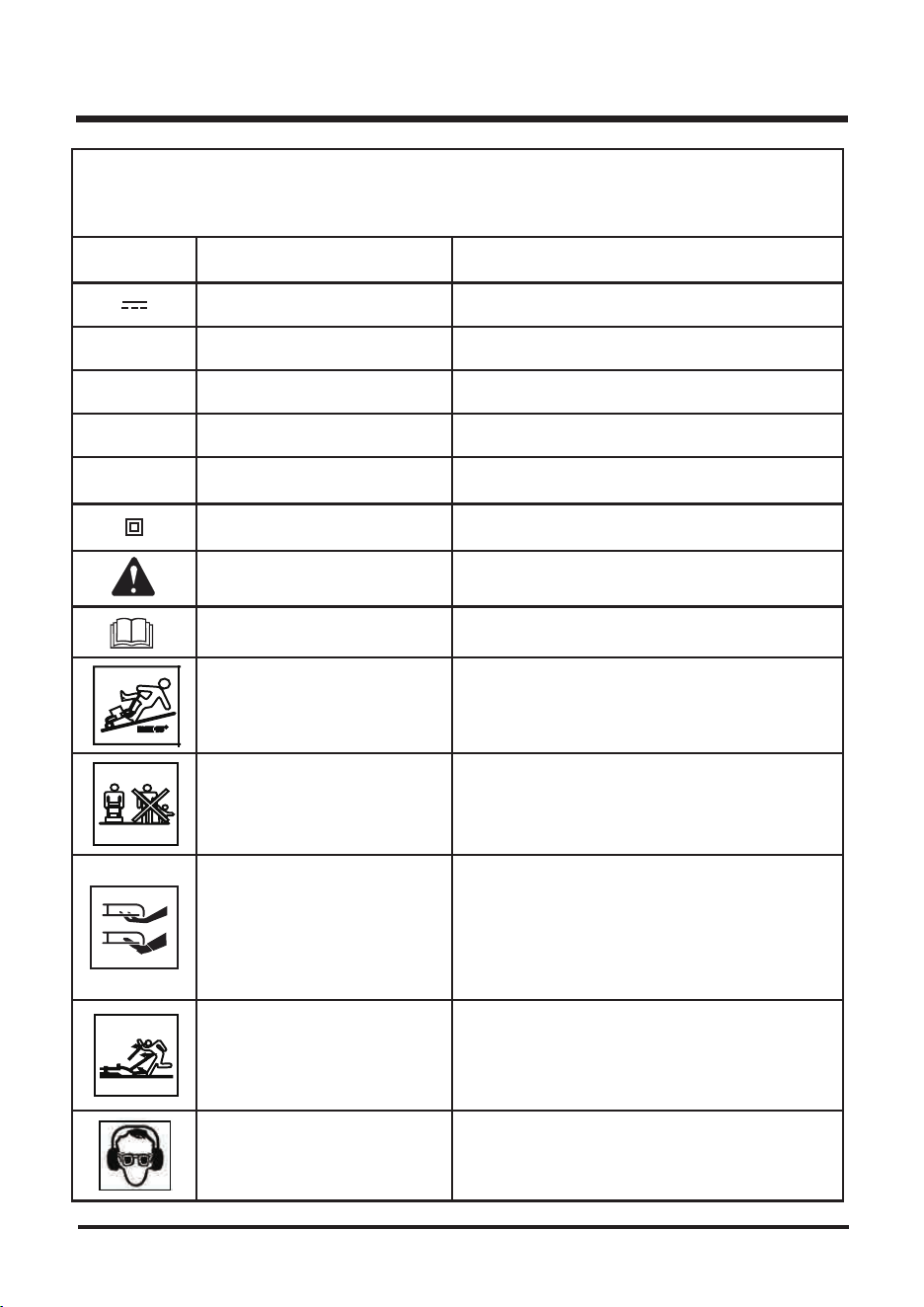
SYMBOLS
Some of the following symbols may be used on this product. Please study them and learn their
meaning. Proper interpretation of these symbols will allow you to operate the product better and safer.
NOITANALPXE/NOITANGISEDEMANLOBMYS
V
A
zH
W
srh
Volts
Do not mow up and down
slopes!
Stay behind the handle when
the motor is running!
Keep hands and feet clear of
mower deck and discharge
opening at all times!
Keep all persons and pets at a
safe distance from the mower
while operating!
Read The Operator’s Manual
Safety Alert
Class II Construction
Hours
Watt
Hertz
Amperes
You must read the operating instructions carefully.
Precaution that invole your safety.
To avoid the risk of injury do not mow up and
down slopes. Always mow across slopes.
( Angle≤15°
)
To avoid the risk of injury to bystanders keep all
persons and pets at a safe distance from the
mower while operating.
Objects struck by mower blade can cause serious
injury. Stay behind the handle when the moto
is running. Always ensure persons and pets are
clear of the discharge from the mower while
operating.
Rotating blades can cause serious injury. Keep
hands and feet clear of mower deck and discharge
opening at all times. Always be sure blade has
stopped after releasing switch lever and unplugging
before removing and replacing collection bag,
cleaning, servicing, transporting or lifting the
mower.
Voltage
Double-insulated construction
Time
Power
Frequency (cycles per second)
Current
Type or a characteristic of currentDirect Current
Eye Protection Wear eye
protection when operating this
equipment.
Safety Alert Precautions that involve your safety.
WARNING
10
SYMBOLS
SERVICE
Servicing requires extreme care and knowledge and should be performed only by a qualified service
technician. For service we suggest you return the product to your nearest SERVICE CENTER for
repair. When servicing, use only identical replacement parts.
To avoid serious personal injury, do not attempt to use this product until you read thoroughly and
understand completely the operator’s manual.
If you do not understand the warnings and instructions in the operator’s manual, do not use this
product. Call customer service for assistance.
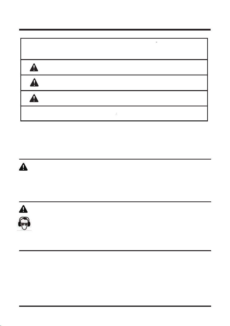
WARNING
The operation of any power tool can result in foreign objects being thrown into your eyes,
which can result in severe eye damage. Before beginning power tool operation, always wear
safety goggles or safety glasses with side shields and, when needed, a full face shield.
We recommend Wide Vision Safety Mask for use over eyeglasses or standard safety glasses with
side shields. Always use eye protection which is marked to comply with ANSI Z87.1.
SYMBO SIGNAL MEANING
DANGER:
Indicates an imminently hazardous situation, which, if not avoided,
will result in death or serious injury.
WARNING:
Indicates a potentially hazardous situation, which, if not avoided,
could result in death or serious injury.
CAUTION:
Indicates a potentially hazardous situation, which, if not avoided, may
result in minor or moderate injury.
CAUTION:
(Without Safety Alert Symbol) Indicates a situation that may result in
property damage.
The following signal words and meanings are intended to explain the levels of risk associated with this
product.
11
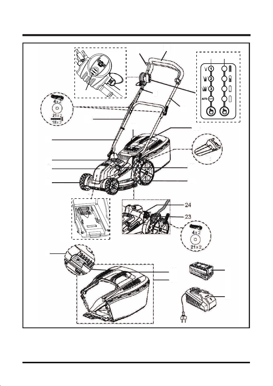
FEATURES
Fig. 1
8b
8a
25b
25c
2
12
10a 10b
25
1
20
3
19
11
10
22
14
16
17
6
7
8
9
5
13
15

FEATURES
NOTE: the above parts and their associated number/letters will be used throughout this manual to
identify parts.
Unpack
This product requires assembly.
■ Carefully remove the product and any accessories from the box. Make sure that all items listed in
the packing list are included. Look under the interior bottom carton flaps for any missing small items.
■ Inspect the product carefully to make sure no breakage or damage occurred during shipping.
■ Do not discard the packing material until you have carefully inspected and satisfactorily operated
the product.
■ If any parts are damaged or missing, please call 1 866-384-8432.
DO NOT TAKE BACK TO WHERE PURCHASED
YOU WILL NEED (ITEMS NOT SUPPLIED)
■ Screwdriver, crosshead
■ Suitable personal protective equipment
12
KNOW YOUR LAWN MOWER (See Fig 1)
The safe use of this product requires an understanding of the information on the product and in this
operator’s manual as well as a knowledge of the project you are attempting.
Before use of this product, familiarize yourself with all operating features and safety rules.
1. Start/stop Bale Switch
2. Safety Switch Button
3. Cord Clips
4. Locking Lever X4
5. Collection Bag Capacity Indicator
6. Lower Handle
7. Mower Carry Handle
8. Battery Compartment Cover
8a. Battery Compartment
8b. Electric Contact X2
9. Wheel
10. ipower Control Panel
10a. ipower Mower Mode Indicator
10b. ipower Battery Meter Indicator
11. Upper Handle
12. Safety Key
13. Collection Bag Handle
14. Safety Flap
15. Collection Bag
16. Cutting Height Adjustment Lever
17. Deck
18. Carriage Bolts X 2
19. Capacity Indicator Flap
20. Foam Grip
21. Washer (Large) X4
22. Mulching Plug
23. Attachment Plate Bolts (one on each side)
24. Tilt Adjustment Mechanism
25. Power Cord
25b. Battery Pack
25c. Charger

13
FEATURES
ASSEMBLY
If any parts are damaged or missing do not operate this product until the parts are replaced. Failure
to heed this warning so could result in serious personal injury.
Do not attempt to modify this product or create accessories not recommended for use with this product.
Any such alteration or modification is misuse and could result in a hazardous condition leading to
possible serious personal injury.
Do not connect power supply until assembly is complete. Failure to comply could result in accidental
starting and possible serious personal injury.
Never operate the mower without the proper safety devices in place and working. Never operate the
mower with damaged safety devices. Failure to heed this warning can result in serious personal injury.
WARNING
PACKING LIST
Mower
Safety Key (must be installed for mower to work)
Mulch Plug - Comes installed from factory at rear of mower
Grass Collection Bag Assembly
Battery Charger
40V Lithium-Ion Battery
Hardware Pack
Operator’s Manual
NOTE: The safety key must be installed for mower to operate. The safety key only fits into the switch
in one direction. DO NOT FORCE IT!!!
ASSEMBLY
14
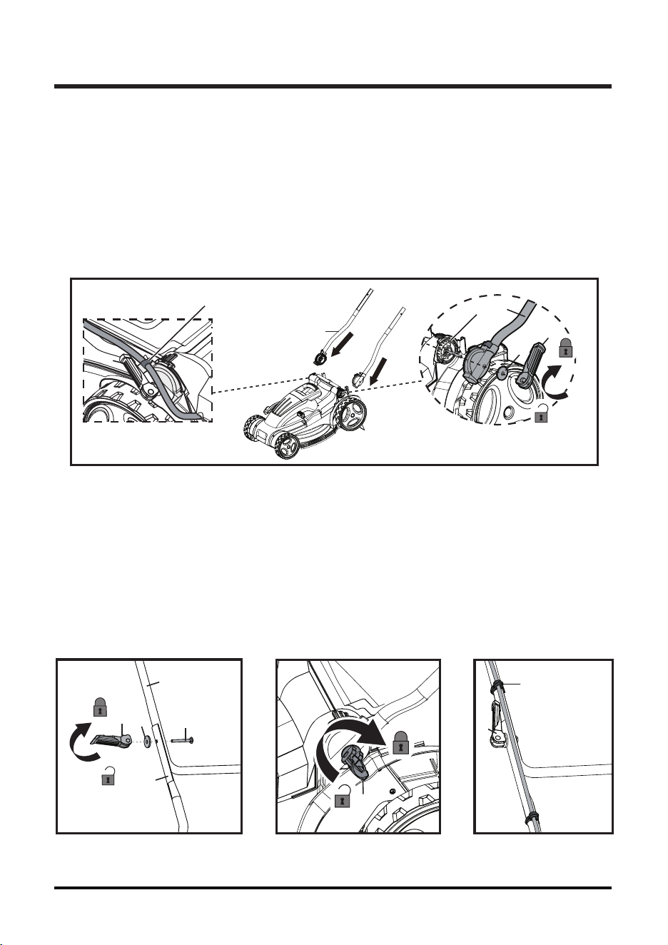
ASSEMBLING THE HANDLE (See Figs. 2-3)
■ Insert lower handles (6) ONTO and over the exposed Attachment plate bolts at the rear of the
motor housing. Make sure the power cord clips (3) on the handles are BOTH facing up.
On each side, place washer (21) over bolt tip and thread locking lever (4) onto it. Fold locking
lever (4) down to secure handle into position. (Fig. 2)
NOTE: For ease of use, the overall handle pitch angle can be raised or lowered by choosing an
attachment point that is higher or lower on the attachment plate. (Fig. 2)
Fig. 3 Fig. 4 Fig. 5
Fig. 2
A - Power Cord Clip
(Sujetador del cable de energía)
B - Attachment Plate
(Placa de fijación)
A
6
4
B
■ Attach the upper handle (11) to the lower handle (6) using attachment plate bolts (23), washer
(21) and locking levers (4).
There are three adjustment positions. Choose the position which is best for you. (Fig. 3)
■ Secure the handle into position by turning the locking lever (4) to tighten and then folding the
lever down. Do not apply excessive force to fold the lever down or it may break. Loosen the
lever to the point where it will fold down without breaking. (Fig. 4)
■ Secure the power cord (25) with the cord clips (3). (Fig. 5)
6
21
4
11
18
21
4
4
4
3
6
ASSEMBLY
15
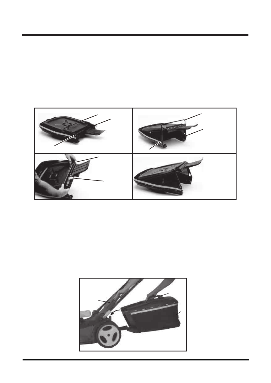
ASSEMBLING THE REDI BAG (COLLECTION BAG) (See Figs. 6)
■ Your Lawnmaster mower comes with a tool-less collection bag (15). Your REDI-bag ships flat
as shown.
■ To assemble the REDI-bag straighten the hinged steel frame at opening of bag as shown.
■ Pry open the long soft plastic tubular sleeve with you fingers and insert the steel frame into the
tube as shown.
■ You fully assembled REDI-bag as shown below.
INSTALLING THE COLLECTION BAG (See Fig. 7)
NOTE: When using the collection bag, do not install the mulch plug (22).
■ Lift the rear safety flap (14).
■ Lift the collection bag by its handle (13) and place
under the rear safety flap (14) so that the hooks
on the collection bag are seated on the door rod.
■ Release the rear safety flap (14).
■ Mulch plug (22) MUST be removed prior to installing
collection bag.
a b
c d
Hinge
Hinge
Steel Frame
Hinge
Steel Frame
Hinge
Soft Plastic
Tube
Steel Frame
REDI-Bag Fully
Assembled
Fig. 7
Fig. 6
14
13
15
ASSEMBLY
Do not connect the battery and/or the isolator key before the product is completely assembled.
WARNING
16
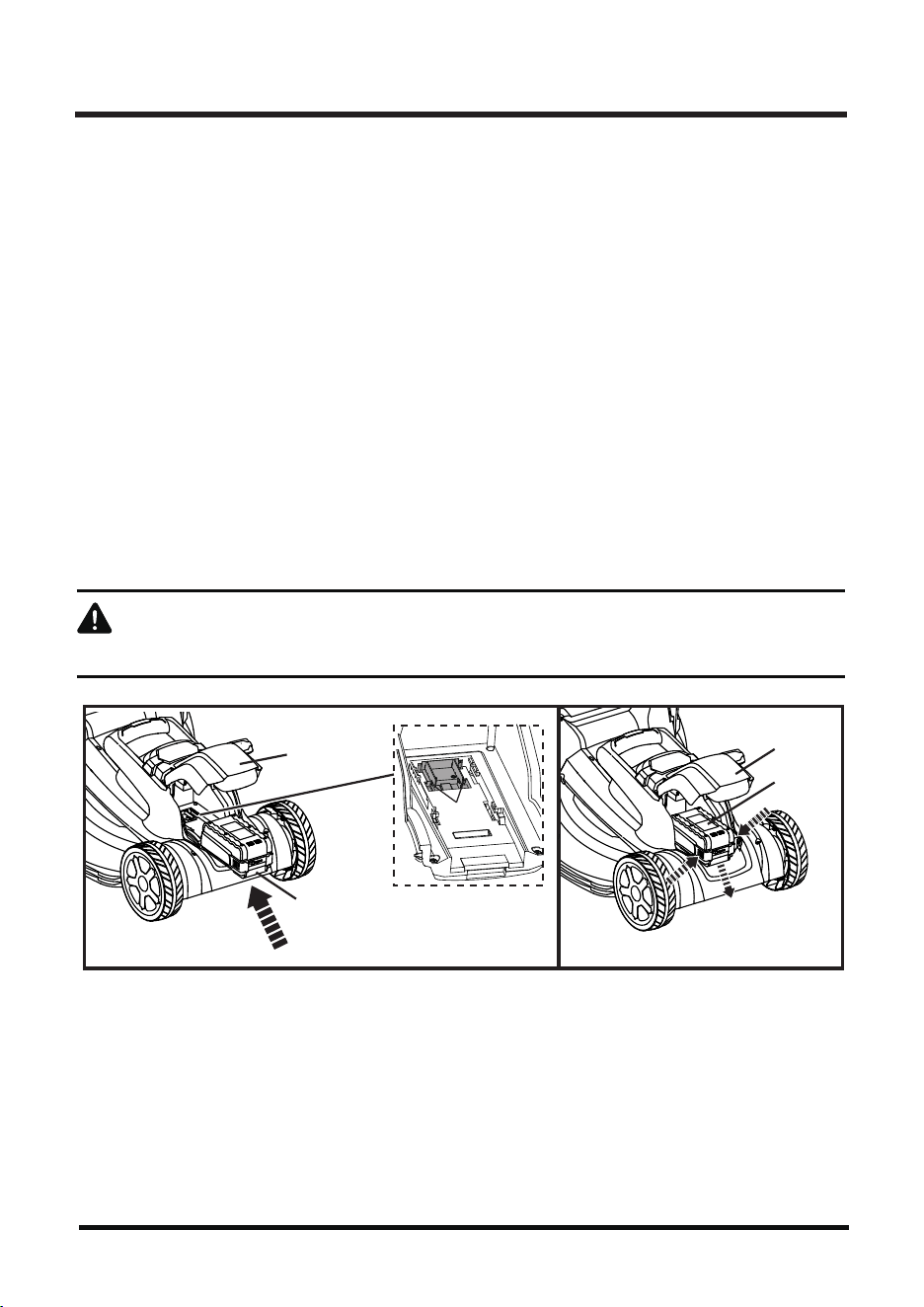
TO INSTALL BATTERY:
■ Open the plastic battery compartment cover (8) at front of mower.
■ Install the battery pack (25b) into the battery compartment (8a) by aligning the battery and sliding
battery until
battery locks into place.
■ The battery pack (25b) can only be installed in one direction. Ensure it slides smoothly along the
support
rails and make sure that the electric contacts (8b) are fully inserted into the battery pack
(25b) and that it snaps into position (Fig. 8).
■
Close the battery battery compartment cover (8).
■
Your product is now ready to be used.
■
Stop the machine. Remove the safety key (12).
■
Open the battery compartment cover (8).
■
Push on both release buttons on the battery pack (25b) (Fig. 9, STEP 1).
■
Slide the battery pack (25b) off the electric contacts (8b) (Fig. 9, STEP 2).
■
Close the battery compartment cover (8).
INSTALL / REMOVE THE BATTERY PACK
INTENDED USE
This cordless lawnmower is designated with the LawnMaster 40V Lithium-Ion battery. The product
is intended for mowing and mulching grass in domestic yards only. It must not be used to mow
unusually high, dry or wet grass, e.g. pasture grass, or for shredding leaves.
This product is intended for private domestic use only, not for any commercial trade use. It must
not be used for any purposes other than those described.
Fig. 8 Fig. 9
8b
8a
25b
STEP 1
STEP 2
25b
8
8
17
ASSEMBLY
SETTING CUTTING HEIGHT (See Fig. 10)
When shipped, the wheels (9) on the mower are set to a low-cutting position. Before using the mower
for the first time, adjust the cutting position to the height best suited for your lawn.
The average lawn should be between 1" to 3".
To set the cutting height: 6 is highest setting 1 is lowest.
■ To raise the cutting height, grasp the cutting height adjustment lever (16) and move it toward the
back of the mower.
■ To lower the cutting height, grasp the cutting height adjustment lever (16) and move it toward the
front of the mower.
Fig. 9Fig. 10
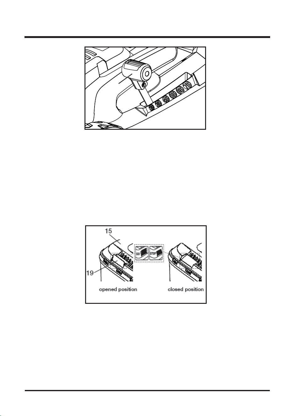
COLLECTION BAG CAPACITY INDICATOR
■ The Collection bag (15) is equipped with a capacity indicator flap (19) that indicates the filling
volume during the mowing process.
■ When the capacity indicator flap (19) is opened (during operation), the Collection bag (15) has
efficient volume left to collect grass.
■ When the capacity indicator flap (19) closes during the mowing operation, the Collection bag (15)
is full and must be emptied (Fig. 11).
Fig. 11
16
ASSEMBLY
18
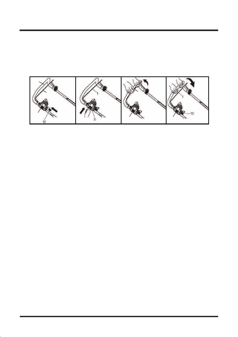
HANDLE TILT ADJUSTMENT
■ The tilt of the handle can be adjusted.
■ Secure the lower handle [6] with the locking lever [4] according to your preference (Fig. 12).
EMPTYING
Empty the collection bag (15) frequently during use. Do not wait until it is completely full.
We recommend emptying it when it is half full.
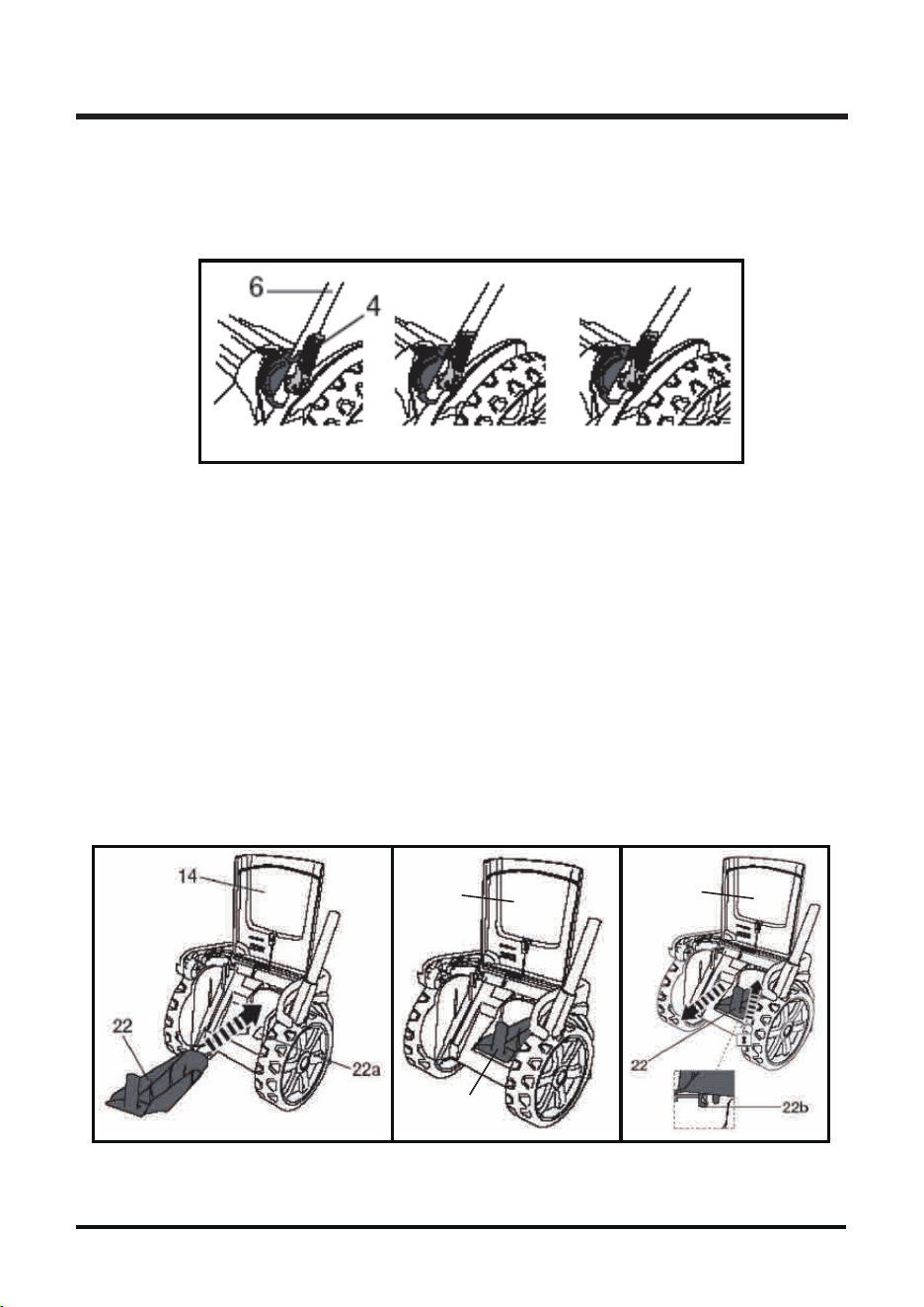
INSTALLING THE MULCHING PLUG
The mulching insert prevents grass from being collected by blocking the collection chute.
This allows the grass clippings to be deposited back on the lawn during cutting.
Do not attach the collection bag (15) and the mulching insert at the same time.
■ To lift the safety flap (14) and detach the grass collection box.
■ Open the safety flap (14), hold it in position and insert the mulching plug into the rear discharge
chute (Fig. 13). Ensure the unlock button snaps into place, as picture shown (Fig. 14 ).
■ Press the unlock button to release and remove the mulching plug (Fig. 15).
Fig. 13 Fig. 14 Fig. 15
Fig. 12
22
14
14
A flashing LED on the cutting mode control panel indicates that the current is too high. A flashing
LED on the battery indicates that the voltage is too low. In either case the motor will be shut down
automatically . Do not continue to activate the On/Off switch if the motor has been shut down
automatically. The battery may be damaged.
WARNING
19
ASSEMBLY
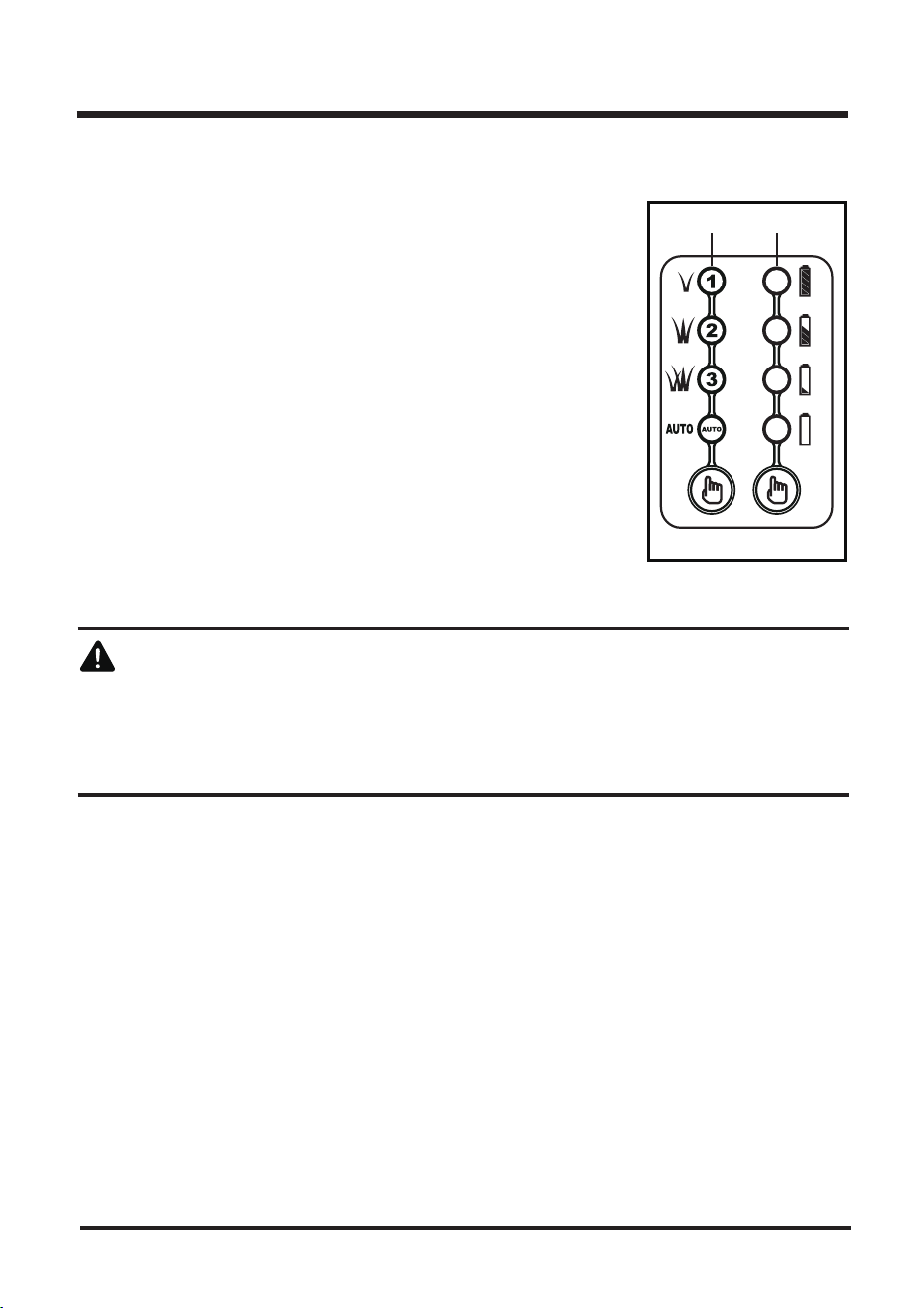
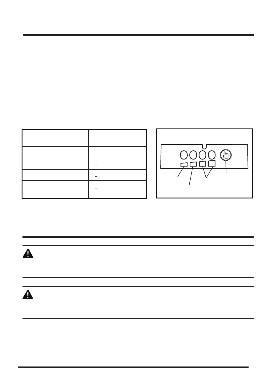
iPOWER MOWER MODE INDICATOR (10a)
(See Fig. 16)
Located on upper mower handle
■
By default, the motor power is set to “AUTO” and will automatically
adjust to your lawn.
■ Push the press button repeatedly to cycle through the different
motor power levels.
• Set the motor power to “1”, if your lawn needs only light mowing.
• Set it to “2”, if you are going to mow taller and thicker grass.
• Set it to “3” to utilize the maximum motor power for mowing the
most stubborn grass.
iPOWER BATTERY METER INDICATOR (10b)
(See Fig. 16)
■ Push the press button to check on the battery status.
■
The number of lights lit will depend on the condition of the battery.
■
lights indicate a fully charged battery, 1 light indicates the battery
needs to be charged.
ipower Control Panel (10)
Fig. 16
10a 10b
GENERAL OPERATION
Check the product, its power cord and plug as well as accessories for damage before each use.
Do not use the product if it is damaged or shows wear.
■ Double check that the blade is properly fixed.
■ Always hold the product by its handles. Keep the handles dry to ensure safe support.
■ Ensure that the air vents are always unobstructed and clear. Clean them if necessary with a soft
brush. Blocked air vents may lead to overheating and damage the product.
■ Switch the product off immediately if you are disturbed while working by other people entering the
working area. Always let the product come to complete stop before removing the grass collection box.
■ Do not overwork yourself. Take regular breaks to ensure you can concentrate on the work and
have full control over the product.
MOWING
■ Make sure the lawn is clear of stones, sticks, wires, and other objects that could damage the lawn
mower blades or motor. Such objects could be accidentally thrown by the mower in any direction
and cause serious personal injury to the operator and others.
■
To reduce the possibility of disconnecting the lawn mower from the extension cord, ensure that the
cord retainer is used.
■ For a healthy plot of grass, always cut off one-third or less of the total length of the grass.
■ When cutting heavy grass; reduce walking speed to allow for more effective cutting and a proper
discharge of the clippings.
■
Do not cut wet grass. It will stick to the underside of the deck (17) and prevent proper mulching of
grass
clippings.
■ New or thick grass may require a narrower cut.
■
Clean the underside of the mower deck (17) after each use to remove grass clippings, leaves, dirt,
and
any other accumulated debris.
20
OPERATION
STARTING / STOPPING
■ To switch on, insert the safety key (12), press and hold the safety switch button (2) and gently pull
the Start/stop bale switch (1) (Fig. 17-19). Once started, release the safety safety switch button (2).
■ To power off the mower, release the Start/stop bale switch (1). Pull out the safety key if the mower
is not going to be used immediately (Fig. 20).
Fig. 17 Fig. 18 Fig. 19 Fig. 20
1
2
20
1
2 2
AFTER USE
■ Switch the product off and let it cool down.
■ Check, clean and store the product as described below.
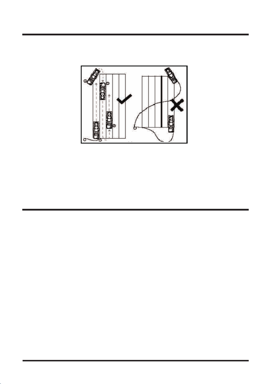
Mow in slight overlapping rows. The most effective pattern for mowing lawns is straight lines along
one of the sides. This will keep the rows even and ensures that all the lawn is cut without missing
any spots (Fig.21).
BATTERY CHARGING
■ Do not use other battery chargers. The battery charger supplied is specifically designed for the
Lithium-Ion battery used in this garden appliance. This ISM device complies with Canadian ICES-001.
■ Check the power voltage! Battery chargers operate on 120 V.
■ The battery is charged between -5 °C and 50 °C. This ensures an optimum battery service life.
■ Protect the battery from heat, from continuous exposure to sun and keep away from radiation or
other heat sources. Do not leave the battery in the mower in direct sunlight over long periods.
■ The battery is supplied partially charged. To ensure full capacity of the battery, charge the battery
before using your appliance for the first time. The
Lithium-Ion
battery can be charged at any time
without reducing its service life. Interrupting the charging procedure does not affect the battery.
■ Always leaves it fully charged if kept in the charger for storage.
CHARGER LEDS
■ If the battery is not inserted, a continuous red LED light indicates that the mains plug is plugged
into a mains socket and the battery charger is ready for operation.
■ Charging: a flashing green LED on the charger indicates that the battery is charging normally.
■ Charged: continuous green LED on the charger indicates that the battery is ready for use.
21
OPERATION
BATTERY PACK AND CHARGER
Fig. 21
■ A flashing red LED light on the charger indicates that the battery temperature is not within -5 °C– 50 °C
or the charging current is too high.
■ After continuous or repeated charging cycles without interruption, the charger may warm up.
This is normal and does not indicate a technical defect of the battery charger.
BATTERY LED PANEL
■ The panel consists of 4 LEDs on the battery. Press and hold the button, then release it, the LEDs
will show you the charge levels. (Fig. 22)
■ The battery’s charge level can be checked either when the battery is attached on the machine or
removed from the machine.
22
When servicing, use only identical replacement parts. Use of any other parts may create a hazard
or cause product damage.
WARNING
Always wear safety goggles or safety glasses with side shields during power tool operation or when
blowing dust. If operation is dusty, also wear a dust mask.
GENERAL MAINTENANCE
Avoid using solvents when cleaning plastic parts. Most plastics are susceptible to damage from
various types of commercial solvents and may be damaged by their use. Use clean cloths to remove
dirt, dust, oil, grease, etc.
WARNING
BATTERY PACK AND CHARGER
MAINTENANCE
Fig. 22
LEDs on battery
(Continuous lighting)
4 LEDs (inc 2 green)
3 LEDs (inc 1 green)
2 LEDs (orange & green)
1 LEDs (red only)
Battery Capacity
Fully charged
Indicator Lights
button
green
orange
red
> 50%
> 25%
< 25%
Recharge required

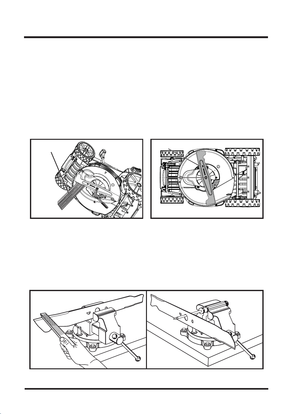
REPLACING THE MOWER BLADE (See Figs. 23,24)
NOTE: Remove safety key and battery before performing any maintenance!!
NOTE: Only use identical replacement blades. LawnMaster mower blade replacement part #RMB4016K.
• Stop the motor and allow the blade to come to a complete stop.
• With blade stopped, remove SAFETY KEY and BATTERY from mower and store in safe location.
• Remove collection bag from mower if attached.
• Slowly turn the mower onto its side.
• Wedge a block of wood between the blade and the mower deck (17) in order to prevent blade from
turning while the blade nut is being removed.
Do not use any attachments or accessories not recommended by the manufacturer of this product.
The use of attachments or accessories not recommended can result in serious personal injury.
Periodically check all nuts and bolts for proper tightness to insure safe operation of the mower.
Remove any buildup of grass and leaves on or around the motor cover. Wipe the mower clean with
a dry cloth occasionally. Do not use water.
LUBRICATION
All of the bearings in this product are lubricated with a sufficient amount of high grade lubricant for
the life of the unit under normal operating conditions. Therefore, no further bearing lubrication is
required. At the beginning and end of each mowing season:
• Lubricate the springs on the rear discharge door with light oil.
• Lubricate the cutting height adjustment lever (16) and related hardware with light oil.
• Remove the wheels (9) and lubricate the surface of the axle bolt and the inner surface of the
wheels (9) with light oil.
• Remove the blade and blade hub assembly and lubricate the motor shaft with light oil or engine
oil. See Replacing the Cutting Blade for instructions on removing the blade.
WARNING
Always protect hands by wearing heavy gloves and/or wrapping the cutting edges of the blade with
rags and other material when performing blade maintenance. Failure to heed this warning could
result in serious personal injury.
WARNING
Before performing any maintenance, make sure the mower is unplugged from the power supply and
battery has been removed. Failure to heed this warning could result in serious personal injury.
WARNING
23
MAINTENANCE
24
MAINTENANCE
■ Loosen the blade nut using a wrench or socket (not provided).
■ Remove the blade nut clounterclockwise,then remove the blade.
■ Make certain the fan assembly is pushed completely against the motor shaft.
■ Place the new blade on the shaft against the fan assembly. Make sure it is installed with the
curved ends pointing up toward the mower deck (17) and not down toward the ground.
■ Thread the blade nut on the shaft and finger tighten.
■ Torque the blade nut down using a torque wrench (not provided) to 25NM (142-159 in.lbs) to
ensure the bolt is properly tightened.
NOTE: Make certain all parts are replaced in the e act order in which they were removed.
SHARPENING THE BLADE (See Fig. 25)
For best mowing performance, the mower blade must be kept sharp. A dull blade does not cut grass
evenly and overloads the motor. Under normal circumstances, sharpening the blade twice during the
mowing season is usually sufficient. However, if your lawn has sandy soil, more frequent sharpenings
may be required.
■ Following the instructions in the Replacing the Cutting Blade section, remove the mower blade.
DO NOT attempt to sharpen the blade while it is attached to the mower.
24 .giF23 .giF
BLADE
WOODEN BLOCK
BO
LT
26 .giF25 .giF
When removing, inspect the blade carefully. If blade is bent or damaged, replace immediately with
a new blade. Failure to replace a bent or damaged blade could cause an accident resulting in
possible serious injury.
WARNING
MAINTENANCE
25
■ Using a fine-tooth file or sharpening stone, sharpen cutting edges on both ends of the blade,
removing equal amounts of material from both ends.
BALANCING THE BLADE (See Fig. 26)
When sharpening, care should be taken to keep the blade balanced. An unbalanced blade will cause
excessive vibration when the mower is running. This vibration will eventually cause damage to the
mower, especially the motor.
To check the blade balance:
■ Clamp a screwdriver horizontally in a vise as shown.
NOTE: If a vise is not available, a straight nail can also be used.
■ Place the center hole of blade on the screwdriver(or nail) shank.
■
If blade is balanced, it will remain in a horizontal position. If either end of the blade drops downward,
sharpen the heavy side until the blade is balanced.
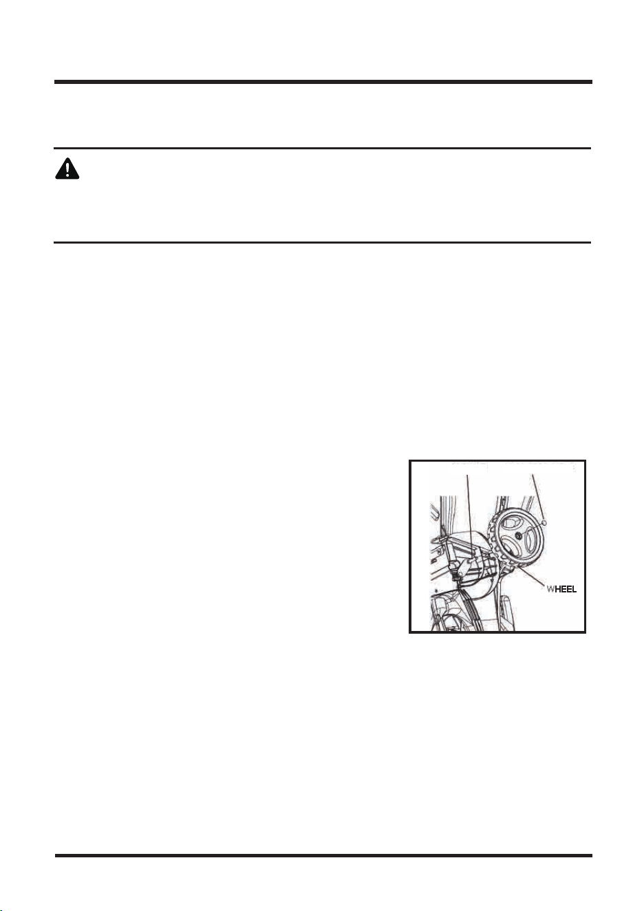
REPLACING WHEELS (See Fig. 27)
To replace a wheel (9):
■ Disconnect the mower from the power supply.
■ Turn the mower on its side.
■ Using a flat blade screwdriver, pry off the locking hubcap.
■ Remove the wheel (9) , replace with new wheel (9) .
■ Replace locking hubcap.
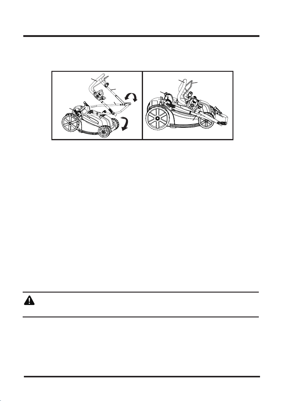
STORING THE MOWER (See Fig. 28-29)
■ Remove mower power key and battery.
■ Turn mower on its side and clean grass clippings that have accumulated on the underside of the
mower deck (17).
■ Wipe the mower clean with a dry cloth.
■ Check all nuts, bolts, knobs, screws, fasteners, etc., for tightness.
■ Inspect moving parts for damage, breakage, and wear. Have repairs made on any damaged or
missing parts.
■ Store mower indoors in a clean, dry place out of the reach of children.
■
Do not store near corrosive materials such as fertilizer or rock salt. To lower the handle before storing:
■
Fully loosen the handle locking levers (4) on the sides of the handle and fold the upper handle (11) down.
AXLE
WHEEL
LOCKING HUBCAP
Fig. 27
26
CHARGER MAINTENANCE
■ Keep the charger clean and clear of debris. Do not allow foreign material into the recessed cavity
or on the contacts. Wipe with a dry cloth. Do not use solvents, water, or place in wet conditions.
■ Always unplug the charger when there is no battery pack in it.
■ Check that the charger contacts have not been shorted by debris or foreign material.
REPLACING THE BATTERY
The mower battery is designed for maximum life; however, like all batteries, will eventually need
to be replaced.
Always charge new batteries before use.
To install a new battery:
■ Remove the safety key (12).
■ Carefully unlock and remove the battery pack (25b).
■ Install the new battery pack (25b).
■ Take the old battery pack to a recycling center that accepts lithium-ion batteries.
Never dispose of battery in fire or regular household trash.
CLEAN THE MOWER
To reduce the risk of electric shock, do not expose the mower to water.
The underside of mower deck (17) should be cleaned after each use as grass clippings, leaves, dirt
and other debris will accumulate causing rust and corrosion.
■ Remove any buildup of grass and leaves on or around the motor cover (do not use water). Wipe
the mower clean with a dry cloth occasionally.
■ If debris build up on the underside of the unit while in use, stop the motor and disconnect it from
the power supply. Tilt the mower forward, or on its side, and scrape it clean with an appropriate tool.
WARNING
MAINTENANCE
■ Push inward on each side of the lower handle (6), and lift the sides of the lower handle (6) past
the edges of the handle mounting brackets.
■ Fold the lower handle (6) forward, making sure not to bend or kink the power cord.
Fig. 28 Fig. 29
6
6
4
20
20
4
11
1

TROUBLESHOOTING
27
PROBLEM POSSIBLE CAUSE SOLUTION
The mower does
not start.
The mower cuts
the grass unevenly.
The mower does
not mulch properly.
The mower is hard
to push.
The mower is
excessively noisy
and vibrates.
The battery is not charged.
The switch is defective.
Grass jammed at blade.
The battery is not attached to
the motor.
Battery may require service or
replacement.
Key is not installed.
The lawn is rough or uneven.
The cutting height is not set
properly.
Wet grass clippings are sticking
to the underside of the deck.
The mulching plug is missing.
The grass is too tall, or the
cutting height is too low.
The rear of the mower housing
and the blade are dragging in
thick grass.
The motor shaft is bent.
The blade is unbalanced.
Charge the battery.
Replace the switch (call the tollfree
helpline, at 1-866-384-8432
Remove battery; check under deck for
jams.
Check the connection between the motor
connector and the battery
Call toll free helpline, at 1-866-384-8432
or replace battery.
Insert the key.
Check the mowing area.
Move the wheels to a higher setting.
Wait until the grass dries before mowing.
Install the mulching plug.
Raise the cutting height.
Empty the grass clippings from the
collection bag.
Stop the motor, and inspect for damage.
See Blade Balancing Section in this
manual. OR replace using LawnMaster
replacement mower part #CLMB4016K.

WARRANTY
28
We take pride in producing a high quality, durable product. This Lawnmaster® product carries a
limited two (2) year warranty against defects in workmanship and materials from date of purchase
under normal household use. If product is to be used for commercial, industrial or rental use, a 30
day limited warranty will apply. Batteries carry a one-year warranty against defects in
workmanship and materials. Batteries must be charged in accordance with the operator's
manual directions and regulations in order to be valid. Warranty does not apply to defects due to
direct or indirect abuse, negligence, misuse, accidents, repairs or alterations and lack of mainte-
nance. Please keep your receipt/packing list as proof of purchase. This warranty gives you
specific legal rights, and you may have other rights, which vary from state to state. For product
service call Customer Service at
1-866-384-8432.
Items not covered by warranty :
1. Any part that has become inoperative due to misuse, commercial use, abuse, neglect, accident,
improper maintenance, or alteration;
2. The unit, if it has not been operated and/or maintained in accordance with the owner's manual;
3. Normal wear, except as noted below;
4. Routine maintenance items such as lubricants, blade sharpening;
5. Normal deterioration of the exterior finish due to use or exposure.
Transportation Charges : Transportation charges for the movement of any power equipment unit or
attachment are the responsibility of the purchaser. It is the purchaser’s responsibility to pay
transportation charges for any part submitted for replacement under this warranty unless such
return is requested in writing by LawnMaster.
SAVE YOUR RECEIPTS. THIS WARRANTY IS VOID WITHOUT THEM.
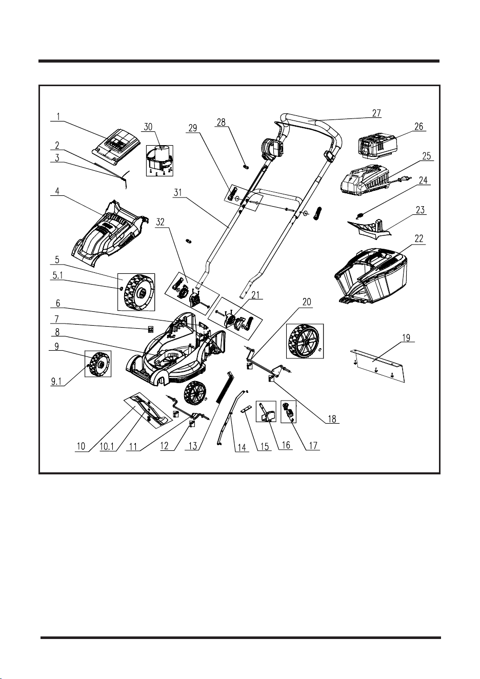
EXPLODED VIEW / PARTS LIST
29

30
EXPLODED VIEW / PARTS LIST
Key Number
1
2
3
4
5
5.1
6
7
8
9
9.1
10
10.1
11
12
13
14
15
16
17
18
19
20
21
22
23
24
25
26
27
28
29
30
31
32
1
1
1
1
2
2
1
1
1
2
2
1
1
1
2
1
1
1
1
1
2
1
1
1
1
1
1
1
1
1
2
2
1
1
1
GMB0BX.20.04
GM01BX.00.09
TOTHYN.05.09
GMD1BX.20.01.X1.03
TGQTGL.62.00.X1.03
BOC2YX.14.NS
GM90BX.00.03
TOQTGX.X0.01
GM90BX.00.01.W5.01
TGQTGL.60.00.X1.03
BOC2YX.13.NS
GMD0BX.00.01.X1.01
GMD0BX.00.01
GMB0BX.00.10
GD41BX.A0.09
TOTHYL.01.17.X1.02
GM01BX.00.30.X1.01
GM86BX.00.02
GMD1BX.30.01.X1.01
GM01BX.00.07.X2.03
GM01BX.00.19.X1.01
GMD5BX.00.01.X1.01
GM01BX.00.50
GM01BX.00.15.X1.08
GM01BX.90.00.02
GM90BX.00.09
TGDQ15.43.50.H6
FO1313.11.00.01
FO2314.11.00.03
GMD4BX.10.00.02
TOQTGX.13.XJ
TGQTXN.05.00.X3.04
TMDCA1.01.00.X2.01
GM01BX.00.12
GM01BX.00.16.X1.08
Drawing Number
Safety Flap
Safety Flap Axle
Safety Flap Spring
Motor Cover Assy
Rear Wheel
Rear Locking Hubcap
Base Connector
Power Cord Retainer
Base Assy
Front Wheel
Front Locking Hubcap
Blade Assy
Blade
Front Wheel Axle
Front Wheel Axle Mounting Bracket
Spring Assy
Height Adjustment Connector
Base Sponge
Height Step Assembly
Height Adjustment Handle
Rear Wheel Axle Mounting Bracket
Protective Buff Assy
Rear Wheel Axle
Lower Left Handle Mounting Bracket
Collection Bag
Mulching Plug
Safety Key
Charger
Battery
Upper Push Handle With Switch Box
Cable Clip
Quick Clamp
Motor Assembly
Lower Handle
Lower Right Handle Mounting Bracket
CLMB4016K MANUAL PARTS LIST
Description
Quantity

31
NOTES