Loading ...
Loading ...
Loading ...

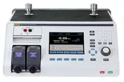
2271A
Operators Manual
56
Smart Transmitters
Smart transmitters are more complex and offer more features that allow the
transmitters to store and transmit more information to a central control center.
For example, many smart transmitters have a digital signal that transmits not only
the analog 4-20 mA signal, but also the pressure reading back to the central
control center. While many newer systems use this digital signal, most still just
use the analog 4-20 mA signal which just requires the analog circuit to be
adjusted when calibrated.
To communicate with smart transmitters, Highway Addressable Remote
Transducer (HART) communication protocol is used. HART is an industry
standard that defines the communications protocol between smart field devices
and a control system that uses traditional 4-20 mA wiring. HART allows the
technician to configure and adjust variables stored and used by the transmitter.
Many of these variables are used to calibrate the smart transmitter. The Electrical
Measurement Module (EMM) is HART-enabled and uses Universal Practice
Commands and many HART Common Practice Commands that let the user
change parameters and make adjustments to the HART device. Many smart
transmitters are designed with specific commands that are not part of the
common practice or universal command library. These commands are
sometimes needed to perform a digital sensor trim (for example) and are referred
to as “device drivers”. The EMM does not contain any device drivers.
Using the mA Function to Test and Troubleshoot
To test the mA output of a pressure transmitter prior to calibration, whether
analog or smart, the Product has a mA menu () that supplies 24 V loop
power while accurately controlling pressure to the transmitter. The menu can
enable or disable 24 V loop power to the transmitter and also can measure dc
voltage up to 30 V.
To test or troubleshoot a pressure transmitter:
1. Connect the transmitter to one of the pressure ports and connect the test
leads from the EMM to the appropriate terminals on the pressure transmitter.
Observe polarity. See Figures 14 and 15. Make sure to plug the other test
port that is not in use.
2. Push on the front panel.
3. Push to turn on 24 V Loop Power ON.
4. Use the pressure controls on the front panel to manually control pressure to
complete the test or troubleshooting. See the Pressure Control section for
information on how to control pressure.
WWarning
To prevent personal injury or damage to the UUT, know the
pressure limitations of the pressure device being tested. The
Product is can control pressure up to 20 MPa (3,000 psi) and
can set pressure when controlling to a setpoint.
5. When finished, push vent to make sure the system is vented and disconnect
the pressure connections and electrical leads.
1.888.610.7664 sales@GlobalTestSupply.com
Fluke-Direct.com
Loading ...
Loading ...
Loading ...