Loading ...
Loading ...
Loading ...

Automated Pressure Calibrator
Module Installation
11
Module Installation
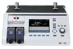
The EMM (located on the top left of the Product front panel) is installed at the
factory. To remove the EMM for service, lift up and pull the module finger tab
outward to slide the EMM out of the Product.
The PMMs (located on the bottom left of the front panel) are delivered in a
separate box and can be installed with the Product turned on or off. The PMMs
can be installed in any order without the need to plug any of the unused slots.
The Product detects the PMM information when installed and shows the
information in the Modules Information screen in the Setup Menu. Information
such as the pressure range of each module is shown on the display after it is
installed.
To install the PMMs, see Figure 3:
WCaution
To prevent damage to the sensors inside the modules, do not
drop the modules.
To prevent contamination of the controller and to ensure proper
operation, the PMM bay must be wiped out regularly to prevent
dirt, dust, and oils from entering the pneumatic system,
especially in dirty or dusty environments. To clean the bay,
wipe it with a cloth that is lightly dampened with water or mild
detergent. Do not use aromatic hydrocarbons, chlorinated
solvents, or methanol based fluids.
1. Remove the PMM from its shipping box.
2. Remove the protective plastic cover from the PMM test and reference port.
3. Confirm that the test and reference port O-rings are properly installed on the
module and are not torn or damaged. Additional O-rings are located in the
box in case they become lost or damaged.
4. Each PMM has a slot on the bottom that fits into the track on the bottom of
the module compartment on the front of the Product. Slot 1 is on the left. Slot
2 is on the right. Line up the track with the slot and slide the PMM into the
compartment until it stops.
5. Turn the knob on the PMM clockwise until it clicks once to secure it.
Note
To prevent accidental over-tightening that can damage the module,
the PMM knob is a torque-limiting knob that slips once the proper
amount of torque is applied.
6. Repeat this procedure for any other PMMs and Barometric Reference
Modules (BRMs).
1.888.610.7664 sales@GlobalTestSupply.com
Fluke-Direct.com
Loading ...
Loading ...
Loading ...