
Loading ...
Loading ...
Loading ...
17
ADJUSTMENTS
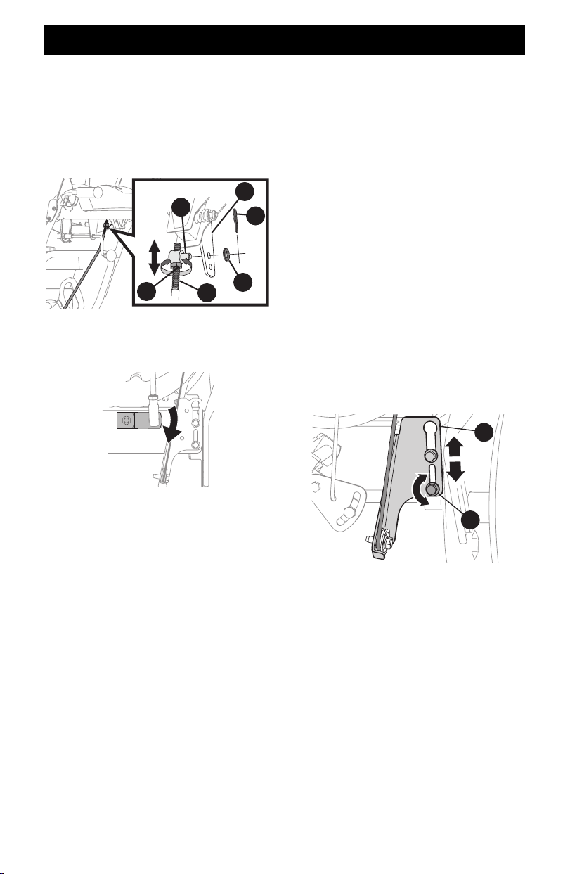
SHIFT ROD IF EQUIPPED
If full range of speeds (forward and reverse) cannot be achieved,
adjust shift rod as follows:
1. Place shift lever in fastest forward speed position.
2. Remove cotter pin (a) and washer (b) from adjustment ferrule
(c) on shift rod (d) and pull it out from shift lever (e)
(Figure 49).
a
e
c
b
d
f
Figure 49
3. Make sure the shift lever on the back of the transmission is
rotated downward to the full extent of its rotation
(Figure 50).
Figure 50
4. Rotate ferrule up or down on shift rod as necessary until it
lines up with upper hole in shift lever (Figure 50 inset).
5. Insert the ferrule into the upper hole and secure with the
washer and hairpin clip.
DRIVE CONTROL IF EQUIPPED
When drive control lever is released and in disengaged “UP”
position, cable should have very little slack. It should NOT be
tight.
NOTE: If excessive slack is present in drive cable or if drive is
disengaging intermittently during operation, the cable may be in
need of adjustment.
Check adjustment of drive control lever as follows:
1. With drive control lever released, push snow blower gently
forward. It should move freely.
2. Engage drive control lever and gently attempt to push the
snow blower forward. The tracks should not move freely.
3. If equipped with a shift lever, with drive control lever
released, move shift lever back and forth between the R2
position and the F6 position several times. There should be no
resistance in the shift lever.
If any of the above tests fail, the drive cable is in need of
adjustment. Proceed as follows:
1. Shut OFF engine, remove safety key or disconnect spark plug
wire. Refer to the Engine Operator’s Manual.
2. Loosen the two hex screws (a) on drive cable bracket (b)
(Figure 51).
a
b
Figure 51
3. Position bracket upward to provide more slack (or downward
to increase cable tension).
4. Re-tighten the hex screws.
5. Check adjustment of drive control lever as described above to
verify proper adjustment has been achieved.
Loading ...
Loading ...
Loading ...