Loading ...
Loading ...
Loading ...
10
ASSEMBLY
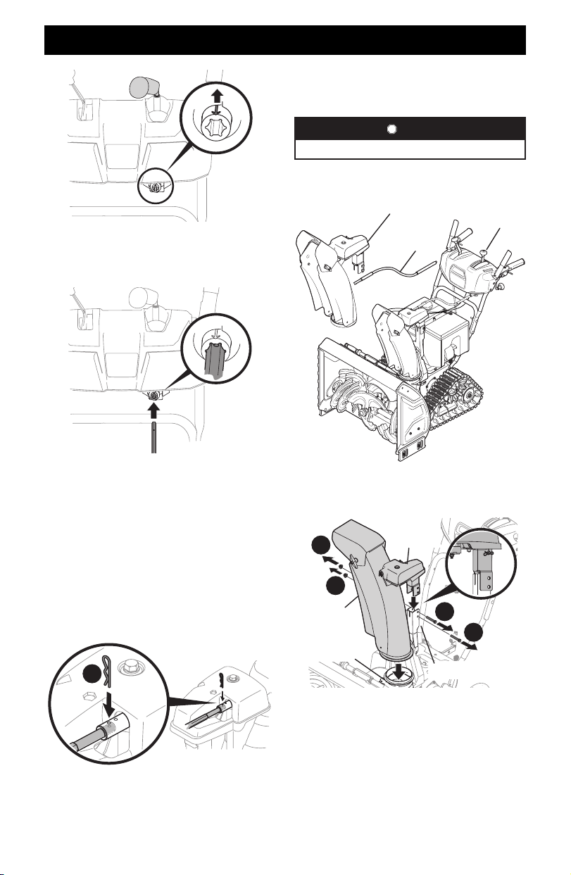
Figure 17
6. Insert chute control rod into pinion gear under handle panel.
Make sure to line up hole in rod with arrow on pinion gear
(Figure 18).
Figure 18
NOTE: Chute control rod will fit snug into pinion gear.
Support rear of handle panel with one hand while inserting
rod with your other hand to ensure rod is inserted all the
way into pinion gear.
NOTE: The hole in the chute control rod is a reference for
aligning rod with indicator arrow on pinion gear, and will be
visible after rod has been fully inserted.
7. Push chute control rod toward control panel until hole in
rod lines up with hole in chute control input collar closest to
chute control head and insert hairpin clip (a) removed in Step
1 (Figure 19).
a
Figure 19
NOTE: Second hole is used to achieve further engagement
of chute control rod into pinion gear, if required. Refer to
Product Care section for Chute Control Rod adjustments.
8. Finish securing chute control head to chute support bracket
with wing nut (b), clevis pin (d), and bow-tie cotter pin (e)
removed in Step 1.
STOP
Continue to Set-Up (page 13).
Overhead Chute Control (Flex Shaft) w/ Steel
Chute & 2-Way Pitch Control
Steel Chute Assembly
Flex Shaft
2-Way Pitch
Control
Figure 20
1. Remove lock nuts (a) and hex screws (b)from chute support
bracket (this will require two wrenches) (Figure 21).
Steel Chute
Assembly
Chute Base
Chute Support Bracket
Chute Control
Head
a
a
b
b
Figure 21
2. Place steel chute assembly onto chute base and chute control
head onto chute support bracket (Figure 21).
3. Secure chute control head to chute support bracket with lock
nuts (a) and hex screws (b) removed in Step 1 (Figure 22).
Loading ...
Loading ...
Loading ...