
Loading ...
Loading ...
Loading ...
16
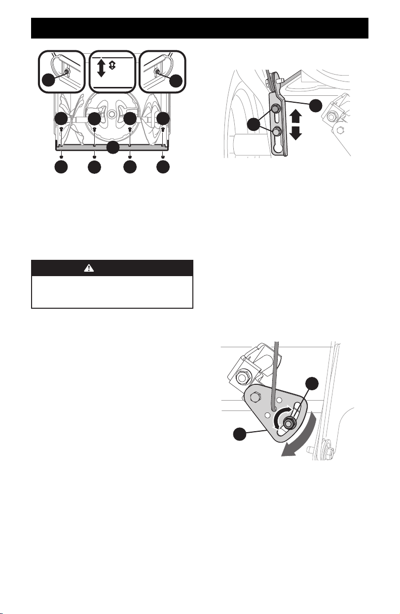
ADJUSTMENTS
d
c
c
c c
b
b
b b
a
a
Figure 46
NOTE: 3-Stage model shown.
4. Adjust the shave plate to one of 2 mounting positions.
Reinstall and securely tighten all carriage bolts, nuts and skid
shoe hardware from Step 3 (Figure 46).
5. Readjust the skid shoes. See Skid Shoes on page 15.
AUGER CONTROL
WARNING
Prior to operating, carefully read and follow all
instructions below. Perform all adjustments to verify
your snow blower is operating safely and properly.
Refer to Auger Control Lever on page 20 for the location of
auger control lever and check adjustment as follows:
1. When auger control lever is released and in disengaged “UP”
position, the cable should have very little slack. It should NOT
be tight.
2. In a well-ventilated area, start the engine. Refer to your
Engine Operator’s Manual.
3. While standing in the operator’s position (behind the
handles), depress the auger control lever to engage auger.
4. Allow auger to remain engaged for approximately ten (10)
seconds before releasing auger control lever. Repeat this
several times.
5. With auger control lever in disengaged “UP” position, walk to
front of machine.
6. Confirm that auger has completely stopped rotating and
shows NO signs of motion. If auger shows ANY signs of
rotating, immediately shut OFF engine, remove safety key or
disconnect spark plug wire. Wait for ALL moving parts to stop
before readjusting auger control lever.
7. Loosen the two hex screws (a) on auger control cable bracket
(b) (Figure 47).
b
a
Figure 47
8. Position auger control bracket (b) upward to provide more
slack in cable (Figure 47).
9. Re-tighten the hex screws.
10. Repeat the steps 1 - 6 to verify proper adjustment has been
achieved.
SHIFT CABLE IF EQUIPPED
If full range of speeds (forward and reverse) cannot be achieved,
adjust shift cable as follows:
1. Place shift lever in fastest forward speed position.
2. Loosen hex nut (a) on shift cable index bracket (b) (Figure 48).
3. Pivot bracket downward to take up slack in cable.
4. Re-tighten hex nut.
5. If further adjustment is necessary move the shift cable to one
of the alternate holes in the shift cable index bracket.
a
b
Figure 48
Loading ...
Loading ...
Loading ...