Loading ...
Loading ...
Loading ...
13
ASSEMBLY
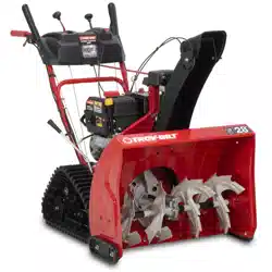
6. Push chute control rod toward the control panel until hole
in rod lines up with middle hole in chute control coupler and
insert hairpin clip (a) removed in Step 1 (Figure 34).
a
Figure 34
NOTE: There is a reference hole provided at rear end of control
rod to help know when holes are vertical.
NOTE: Hole furthest from chute control head is used to
achieve further engagement of chute control rod into coupler,
if required. Refer to Adjustments, Overhead Chute Control on
page 15.
NOTE: For models equipped with manual chute control rods,
the hole closest to chute control head is used for manual
movement of chute assembly, if required. Refer to Operation,
Manual Chute Rotation Control & Electric Chute Control on
page 21.
STOP
Continue to Set-Up (page 13).
Set-Up
CHUTE CONTROL CABLE ROUTING IF EQUIPPED
For models equipped with 2-way or 4-way chute controls,
electric chute control and/or chute-pitch controls, ensure control
cables are routed properly.
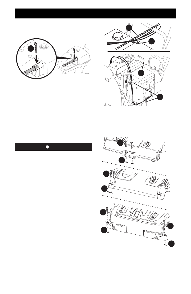
Chute control cables are routed through a single wire guide (a) on
top of the engine and/or through two wire guides (b) located on
the front and left side of the engine (Figure 35).
NOTE: On models equipped with a cable tie securing the cables to
the rear of the gas tank, pull the cables toward the chute and pull
the cable tie snug to secure the cables in place.
NOTE: For smoothest operation, cables should all be to the left of
the chute control rod (c).
NOTE: The number of cables routed through the wire guides will
vary depending on model.
1. Locate cable guide(s) and perform the following:
• Top Mounted Wire Guide (a) - Check that all cables are
properly routed through cable guide on top of engine
(Figure 35).
• Front and Side Mounted Wire Guides (b) - Check that all
cables are properly routed through the wire guide below the
left side of the engine and the wire guide below the chute
control head (Figure 35).
a
c
c
b
Figure 35
SHEAR PINS STORAGE IF EQUIPPED
On select models, holes are provided in the rear of the handle
panel for shear pin (a) and bow-tie cotter pin (b) storage as
shown in Figure 36. If not provided, make sure to store them in a
safe place until needed.
a
a
a
b
b
b
b
a
Figure 36
Loading ...
Loading ...
Loading ...