Loading ...
Loading ...
Loading ...
190 Series III
Users Manual
44
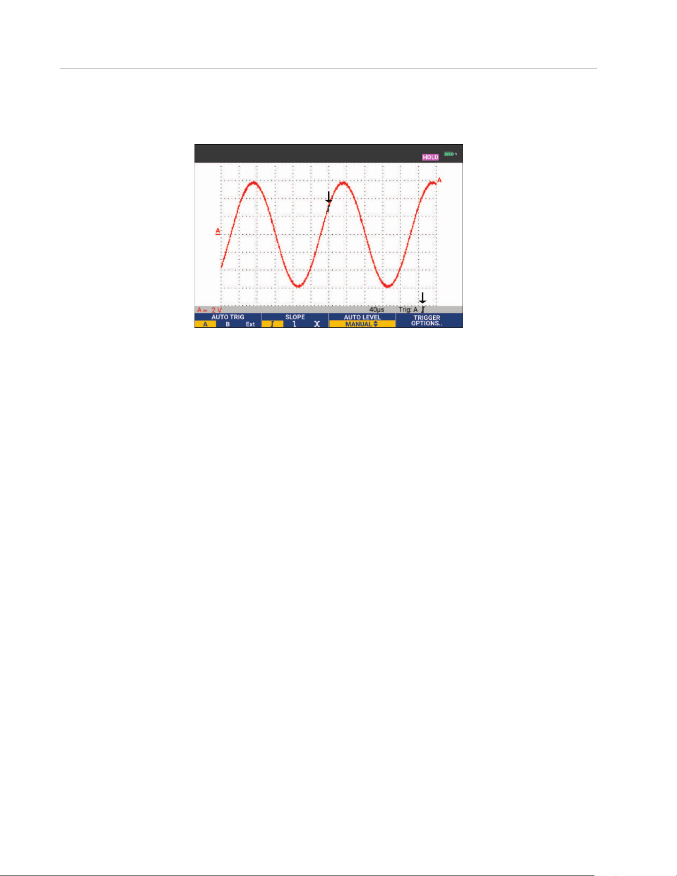
At the bottom of the screen the trigger parameters show. See Figure 25. For example, input A is
used as the trigger source with a positive slope.
Figure 25. Screen with all Trigger Information
When a valid trigger signal is found, the trigger key will be lit and the trigger parameters appear in
black. When no trigger is found, the trigger parameters appear in gray and the key light will be
off.
Trigger Delay or Pre-Trigger
You can begin to display the waveform some time before or after the trigger point has been
detected. Initially, you have a half screen (6 divisions) of pre-trigger view (negative delay).
To set the trigger delay:
1. Press and hold down
N to adjust the trigger delay.
Observe that the trigger icon on the screen moves to show the new trigger position. When the
trigger position moves left off of the screen, the trigger icon changes to indicate that you have
selected a trigger delay. Moving the trigger icon to the right on the display gives you a pre-trigger
view. This allows you to see what happened before the trigger event, or what caused the trigger.
In case of a trigger delay, the status at the bottom of the screen changes. See Figure 26. For
example, input A is used as the trigger source with a positive slope. The 500.0 ms indicates the
(positive) delay between trigger point and waveform display. When a valid trigger signal is found,
the trigger key will be lit and the trigger parameters appear in black. When no trigger is found, the
trigger parameters appear in gray, ands the key light will be off.
1.888.610.7664 sales@GlobalTestSupply.com
Fluke-Direct.com
Loading ...
Loading ...
Loading ...