Loading ...
Loading ...
Loading ...
SDS5000X Series Digital Oscilloscope User Manual
111 / 2 3 6 W W W. S I G L E N T. C O M
16.2 I2C Trigger and Serial Decode
This section covers triggering and decoding I2C signals. Please read the
following for more details: "I2C Signal Settings", "I2C Trigger" and "I2C Serial
Decode".
16.2.1 I2C Signal Settings
Connect the serial data signal (SDA) and serial clock signal (SCL) to the
oscilloscope, set the mapping relation between channels and signals and then
set the threshold level of each signal. The signal settings of decode and trigger
are independent. If you want to synchronize the settings between decode and
trigger, please perform Copy Setting in the decode dialog box.
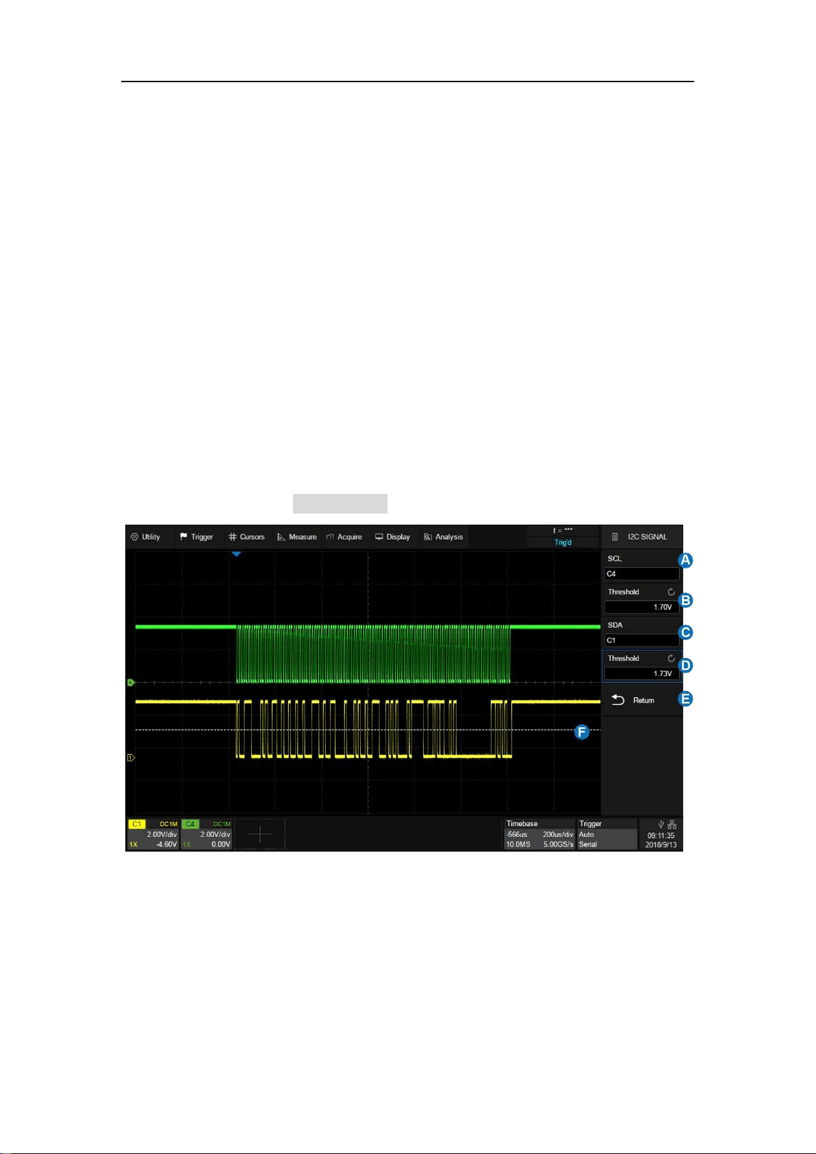
A. Set the source of SCL. In the example above, SCL is connected to C4.
B. Set the threshold level of SCL. It is 1.7 V for the LVTTL signal in this
example.
C. Set the source of SDA. In the example above, SDA is connected to C1.
D. Set the threshold level of the SDA channel.
Loading ...
Loading ...
Loading ...