Loading ...
Loading ...
Loading ...
7. SY N T H | 39
FILTER FREQUENCY
The morphable filter FREQ knob is used for setting the
cut-off frequency point – that is where in the frequency
range the filter begins to process frequencies. The
actual result of this processing depends on the type of
filter used.
The Image above illustrates three different Filter Frequency settings using
a low pass filter. The area to the left, up to the downward slope indicates
the frequencies that passes through the filter. The area to the right of the
slope are those frequencies that are reduced. Move the slope to the left
and the sound gets duller. The “humps” at the top indicate a resonance
setting.
FILTER RESONANCE
The morphable Resonance (RES) parameter is used to
further adjust the characteristics of the filter. Increas-
ing the Resonance will emphasize frequencies around
the cutoff frequency, making the sound thinner.
Further raising the Resonance will make the sound
resonant to a point where the filter starts to self-oscillate and produce
a ringing pitch. Exactly where in the frequency spectrum this “ringing”
occurs, depends on the Frequency value.
When the LP/HP filter setting is used the RES knob instead controls the
high-pass cut-off frequency, as indicated by the FREQ HP text.
KB TRACK
The reason for controlling keyboard track is related to
basic acoustics. If the pitch of a waveform is raised, the
harmonics naturally raise in frequency as well. If the cutoff
frequency is constant, the sound will be perceived as
getting “muddier” the higher up the keyboard you play. To
avoid this effect, use KB TRACK.
KB TRACK SETTINGS
Off (no LEDs being lit): The filter frequency cut-off point is not altered by
the note played.
1/3: The cut-off frequency will track the keyboard in a 1:3 relationship.
Play one octave higher and the cutoff frequency will move by 1/3 of an
octave.
2/3: The cut-off frequency will track the keyboard in a 2:3 relationship,
play one octave higher and the cutoff frequency will move by 2/3 of an
octave.
1: The cut-off frequency will track the keyboard in a 1:1 relationship.
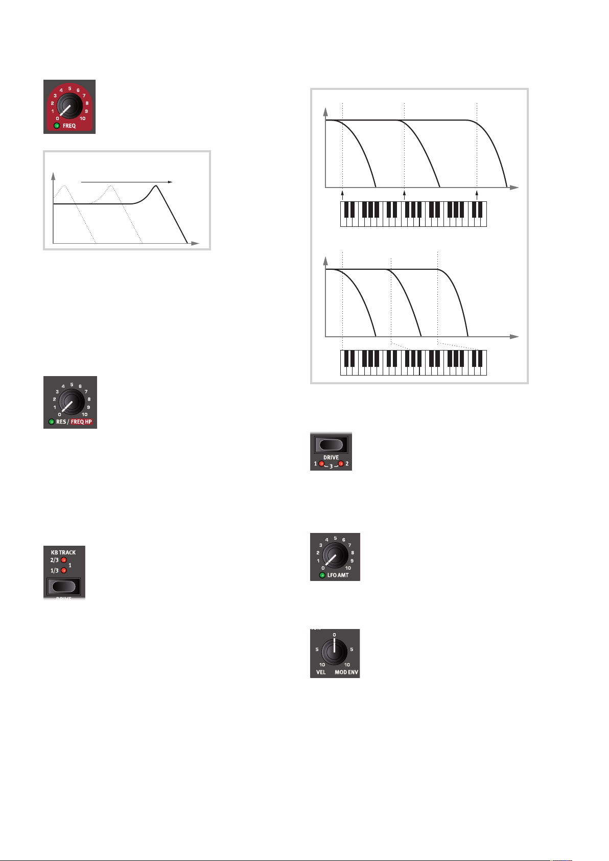
The diagrams below illustrate the relationship between keyboard posi-
tion and cut-off frequency at the 1:1 and 2/3 settings:
DRIVE
Activating DRIVE (Shift + KB Track) adds distortion to
the Filter stage. The 1, 2 and 3 settings represent low,
medium and high amounts of drive respectively.
Using Drive with high Filter Resonance settings will
often produce fun and/or interesting results.
LFO AMT
The filter frequency can be controlled by the low
frequency oscillator, the LFO. The morphable LFO AMT
knob sets the amount of modulation. The exact effect
of the LFO Amt parameter depends on how the LFO
section is set up, see page 40.
VEL / MOD ENV
The two-way VEL / MOD ENV knob governs the
amount of modulation to the filter frequency either by
keyboard velocity or by the modulation envelope. At
the center, “12 o’clock”, position no Velocity or Mod
Env modulation is applied to the filter.
Turning the knob counter-clockwise from the 12 o’clock zero setting
gives an increasing amount of velocity control. Turning the knob
clockwise from 12 o’clock, the modulation envelope will modulate the
frequency with an increasing amount.
filter frequency
freq
gain
freq
gain
1:1 Tracking
freq
gain
2/3 Tracking
Loading ...
Loading ...
Loading ...