Loading ...
Loading ...
Loading ...
Perlick is committed to continuous improvement. Therefore, we reserve the right to change specications without prior notice
8
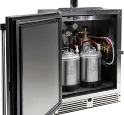
PERLICK NITRO BEVERAGE DISPENSING KIT
Operation/Installation Manual
1. Drill six mounting holes according to Operation 1 via an
electric drill and a 5/32” drill bit.
2. Determine how many nitrogen lines are needed for you
application. Cut to length (leave room for error) and mount
the gas lines to the air distributor with worm-drive clamps
and a 1/4” hex-nut driver (Reference Operation 2).
3. Mount the 6-way air distributor by aligning its holes with
the drilled holes in Operation 1. Install two self-tapping
screws from the parts bag with a drill and 5/16” hex bit
according to Operation 2.
4. Install the nitrogen source inside or outside the
refrigeration unit according to Operation 3.
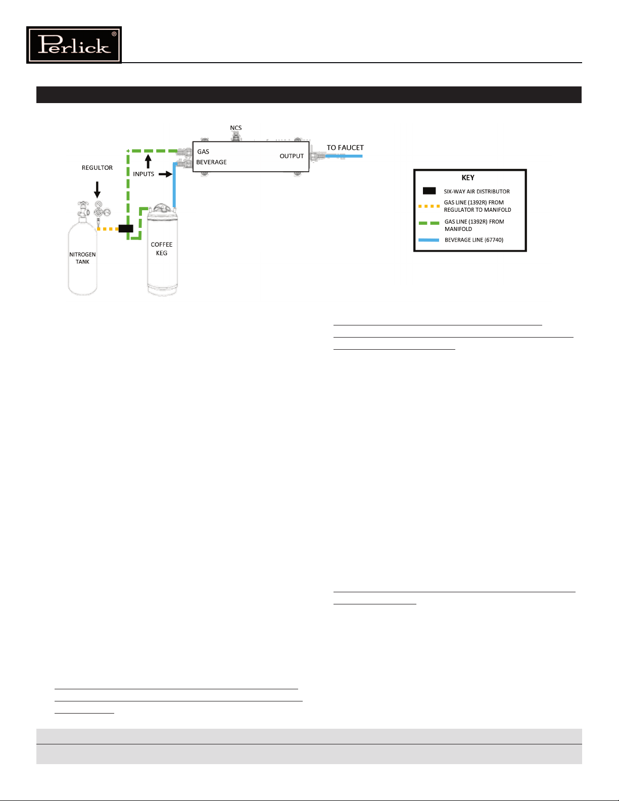
5. Connect a red gas line to the regulator (Fig. 5) and to the
inlet of the 6-way air distributor (Fig. 4). Use a worm drive
clamp for each gas line and a 1/4” nut driver (Reference
Operation 3).
6. Install the regulator to the nitrogen source using a large
adjustable wrench and teon tape for the threaded
connection (Reference Operation 3). Ensure the tank and
regulator are set to their closed positions (gure 17).
7. Install one gas line from the 6-way air distributor and
one new beverage line to the nitro infuser’s inputs with a
worm drive clamp and cut o threaded connector for the
beverage line according to Operation 4.
8. Install one beverage line to the output beverage
connection on the infuser via a worm drive clamp
(Reference Operation 4).
9. Mount the nitrogen infuser to holes drilled in Step 1 above
using the small black screws from the infuser and a phillips
bit and drill.
10. Attach the beverage line from the input of nitro infuser to
a black quick disconnect with a worm drive clamp and 1/4”
hex-nut driver (Reference Operation 5).
11. Repeat Step 8 but attach a red gas line from the air
distributor to the gray quick disconnect with a worm drive
clamp and 1/4” hex-nut driver (Reference Operation 5).
12. Connect the quick disconnects to the keg(s) by lifting up
on the outer ring (Reference Operation 6).
a) Black quick disconnect attaches to out.
b) Gray quick disconnect attaches to in.
13. Connect the output beverage line from the infuser (and
any other beverage lines) to the tower (Operation 7). Cut
o connectors if the tower has a hose barb, and not a
threaded connection.
14. Mount the faucets to the tower and the tower to
refrigeration cabinet (Reference Operation 8).
15. Install the air scoop according to Operation 9.
16. If a nitrogen tank is being used inside the refrigeration unit,
connect both ends of the safety chain and wrap the chain
around the tank. Drive a self-taping screw through the
chain.
17. Ensure that the tank, regulator and all non-used gas lines
are set to a closed position (Fig. 18).
18. Using the adjustable screw on the front of the regulator,
adjust the pressure to 28 PSI for optimal dispensing.
19. Adjust the NCS dial on the infuser to the desirable output
for coee and froth.
20. Open the gas tank and set the regulator to an open
position.
21. Allow the beverage 1-2 minutes to pressurize and serve!
ASSEMBLY INSTRUCTIONS FOR SINGLE NITROGEN INFUSER KIT
(
1030849, RS
-
NDK
)
All Components shown are reference only
Fig. 1
(Line Setup Check for Single Infuser)
Loading ...
Loading ...
Loading ...