Loading ...
Loading ...
Loading ...
RemoteThermostatControl(onsomemodels)(remote
wallthermostatinstalled)
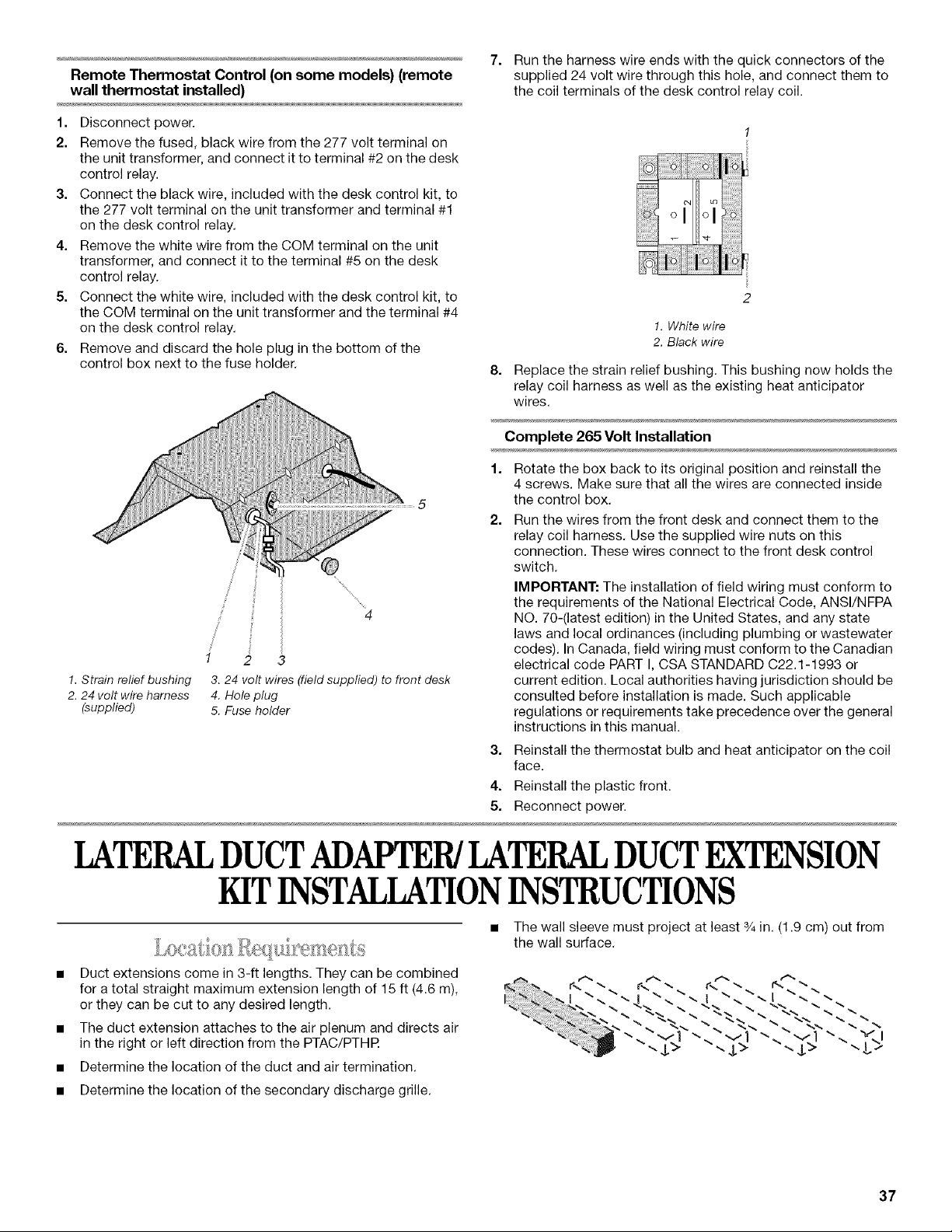
7. Run the harness wire ends with the quick connectors of the
supplied 24 volt wire through this hole, and connect them to
the coil terminals of the desk control relay coil.
1. Disconnect power.
2. Remove the fused, black wire from the 277 volt terminal on
the unit transformer, and connect it to terminal #2 on the desk
control relay.
3. Connect the black wire, included with the desk control kit, to
the 277 volt terminal on the unit transformer and terminal #1
on the desk control relay.
4. Remove the white wire from the COM terminal on the unit
transformer, and connect it to the terminal #5 on the desk
control relay.
5. Connect the white wire, included with the desk control kit, to
the COM terminal on the unit transformer and the terminal #4
on the desk control relay.
6. Remove and discard the hole plug in the bottom of the
control box next to the fuse holder.
8=
i
1. White wire
2. Black wire
Replace the strain relief bushing. This bushing now holds the
relay coil harness as well as the existing heat anticipator
wires.
Complete 265 Volt Installation
1 2 3
1. S train relief bushing 3.24 volt wires (field supplied) to front desk
2. 24 volt wire harness 4. Hole plug
(supplied) 5. Fuse holder
2=
Rotate the box back to its original position and reinstall the
4 screws. Make sure that all the wires are connected inside
the control box.
Run the wires from the front desk and connect them to the
relay coil harness. Use the supplied wire nuts on this
connection. These wires connect to the front desk control
switch.
IMPORTANT: The installation of field wiring must conform to
the requirements of the National Electrical Code, ANSI/NFPA
NO. 70-(latest edition) in the United States, and any state
laws and local ordinances (including plumbing or wastewater
codes). In Canada, field wiring must conform to the Canadian
electrical code PART I, CSA STANDARD C22.1-1993 or
current edition. Local authorities having jurisdiction should be
consulted before installation is made. Such applicable
regulations or requirements take precedence over the general
instructions in this manual.
3. Reinstall the thermostat bulb and heat anticipator on the coil
face.
4. Reinstall the plastic front.
5. Reconnect power.
LATERALDUCTADAFI R/LATERAL DUCTEXTENSION
KIT INSTALLATIONINSTRUCTIONS
• The wall sleeve must project at least 3/4in. (1.9 cm) out from
the wall surface.
Duct extensions come in 3-ft lengths. They can be combined
for a total straight maximum extension length of 15 ft (4.6 m),
or they can be cut to any desired length.
The duct extension attaches to the air plenum and directs air
in the right or left direction from the PTAC/PTHR
Determine the location of the duct and air termination.
r<" -. r-.'" "-
• Determine the location of the secondary discharge grille.
37
Loading ...
Loading ...
Loading ...