Loading ...
Loading ...
Loading ...
DISCONNECTSWITCHINSTALLATIONINSTRUCTIONS
Parts Required
• 12 AWG green wire
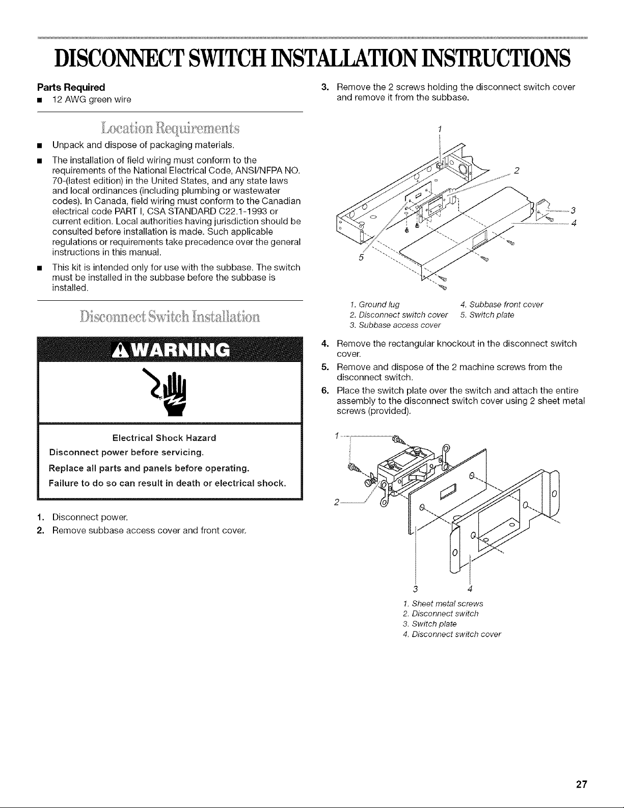
3. Remove the 2 screws holding the disconnect switch cover
and remove it from the subbase.
Unpack and dispose of packaging materials.
The installation of field wiring must conform to the
requirements of the National Electrical Code, ANSI/NFPA NO.
70-(latest edition) in the United States, and any state laws
and local ordinances (including plumbing or wastewater
codes). In Canada, field wiring must conform to the Canadian
electrical code PART I, CSA STANDARD C22.1-1993 or
current edition. Local authorities having jurisdiction should be
consulted before installation is made. Such applicable
regulations or requirements take precedence over the general
instructions in this manual.
This kit is intended only for use with the subbase. The switch
must be installed in the subbase before the subbase is
installed.
Electrical Shock Hazard
Disconnect power before servicing.
Replace all parts and panels before operating.
Failure to do so can result in death or electrical shock.
1. Disconnect power.
2. Remove subbase access cover and front cover.
,%
1. Ground lug 4. Subbase front cover
2. Disconnect switch cover 5. Switch plate
3. Subbase access cover
4. Remove the rectangular knockout in the disconnect switch
cover.
5. Remove and dispose of the 2 machine screws from the
disconnect switch.
6. Place the switch plate over the switch and attach the entire
assembly to the disconnect switch cover using 2 sheet metal
screws (provided).
3
1. Sheet metal screws
2. Disconnect switch
3. Switch plate
4. Disconnect switch cover
27
Loading ...
Loading ...
Loading ...