Loading ...
Loading ...
Loading ...
IMPORTANT: The next steps require you to make permanent
modifications to the decorative side skirts. The modifications are
for left and right sides, and the skirts will not be interchangeable
after modification.
NOTE: If the subbase is to be used only for structural support of
the PTAC/PTHP, you do not need to read this section on making
electrical connections.
Electrical Shock Hazard
Disconnect power before servicing.
Replace all parts and panels before operating.
Failure to do so can result in death or electrical shock.
230/208 volt power supply
• In 230/208 volt applications, a field-supplied NEC approved
receptacle can be installed in the subbase along with the
optional disconnect switch accessory.
g,
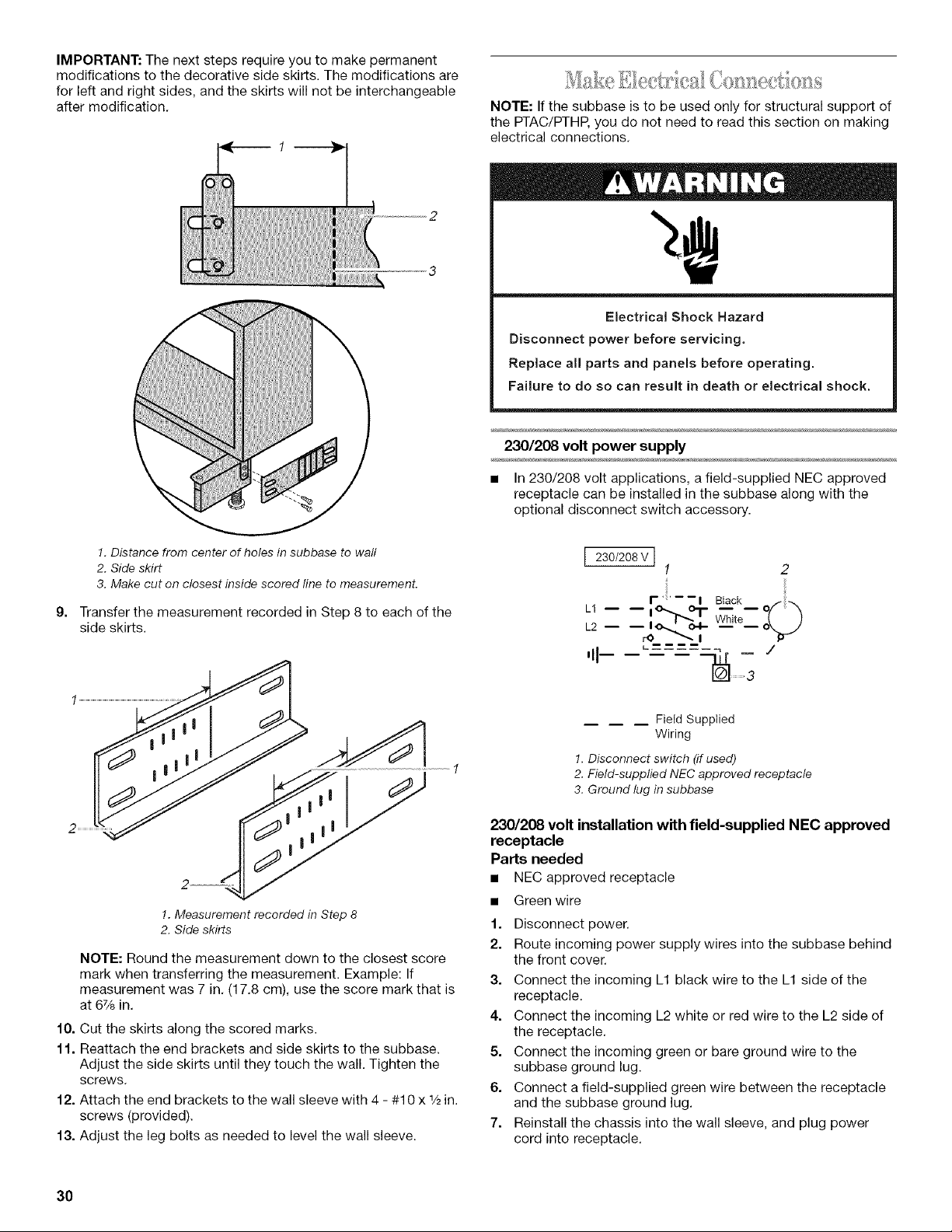
1. Distance from center of holes in subbase to wall
2. Side skirt
3. Make cut on closest inside scored line to measurement.
Transfer the measurement recorded in Step 8 to each of the
side skirts.
1. Measurement recorded in Step 8
2. Side skirts
NOTE: Round the measurement down to the closest score
mark when transferring the measurement. Example: If
measurement was 7 in. (17.8 cm), use the score mark that is
at 6% in.
10. Cut the skirts along the scored marks.
11. Reattach the end brackets and side skirts to the subbase.
Adjust the side skirts until they touch the wall. Tighten the
screws.
12. Attach the end brackets to the wall sleeve with 4 - #10 x _/2in.
screws (provided).
13. Adjust the leg bolts as needed to level the wall sleeve.
I 230/208V I
1
r"--i Black
u -- -- ,_.h...oT
L2 I_. 04- White
r¢_ I
'11
/
Field Supplied
Wiring
1. Disconnect switch (if used)
2. Field-supplied NEC approved receptacle
3. Ground lug in subbase
230/208 volt installation with field-supplied NEC approved
receptacle
Parts needed
• NEC approved receptacle
• Green wire
1. Disconnect power.
2. Route incoming power supply wires into the subbase behind
the front cover.
3. Connect the incoming L1 black wire to the L1 side of the
receptacle.
4. Connect the incoming L2 white or red wire to the L2 side of
the receptacle.
5. Connect the incoming green or bare ground wire to the
subbase ground lug.
6. Connect a field-supplied green wire between the receptacle
and the subbase ground lug.
7. Reinstall the chassis into the wall sleeve, and plug power
cord into receptacle.
3O
Loading ...
Loading ...
Loading ...