Loading ...
Loading ...
Loading ...
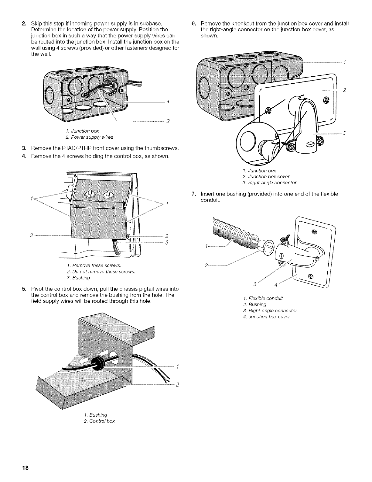
2,
Skip this step if incoming power supply is in subbase.
Determine the location of the power supply. Position the
junction box in such a way that the power supply wires can
be routed into the junction box. Install the junction box on the
wall using 4 screws (provided) or other fasteners designed for
the wall.
6. Remove the knockout from the junction box cover and install
the right-angle connector on the junction box cover, as
shown.
3,
4.
!. Junction box
2. Power supply wires
Remove the PTAC/PTHP front cover using the thumbscrews.
Remove the 4 screws holding the control box, as shown.
7,
1. Junction box
2. Junction box cover
3. Right-angle connector
Insert one bushing (provided) into one end of the flexible
conduit.
5,
!. Remove these screws.
2. Do not remove these screws.
3. Bushing
Pivot the control box down, pull the chassis pigtail wires into
the control box and remove the bushing from the hole. The
field supply wires will be routed through this hole.
3 4
!. Flexible conduit
2. Bushing
3. Right-angle connector
4. Junction box cover
1
%
2
1. Bushing
2. Control box
18
Loading ...
Loading ...
Loading ...