Loading ...
Loading ...
Loading ...
7. Run the harness wire ends with the quick connectors through
the hole and connect them to the coil terminals of the desk
control relay coil.
i
2
1. White wire
2. Black wire
8. Snap the strain relief bushing (provided) over the wire harness
and insert it into the hole in the control box. Be sure that there
is enough wire slack inside the control box to rotate the
control box fully opened.
Complete 230/208 Volt Installation
2=
Rotate the box back to its original position and reinstall the
4 screws. Make sure that all the wires are connected inside
the control box.
Run the wires from the front desk and connect them to the
relay coil harness. Use the supplied wire nuts on this
connection. These wires connect to the front desk control
switch.
IMPORTANT: The installation of field wiring must conform to
the requirements of the National Electrical Code, ANSl/NFPA
NO. 70-(latest edition) in the United States, and any state
laws and local ordinances (including plumbing or wastewater
codes). In Canada, field wiring must conform to the Canadian
electrical code PART I, CSA STANDARD C22.1-1993 or
current edition. Local authorities having jurisdiction should be
consulted before installation is made. Such applicable
regulations or requirements take precedence over the general
instructions in this manual.
3. Reinstall the thermostat bulb and heat anticipator on the coil
face.
4. Reinstall the plastic front.
5. Reconnectpowe_
Each desk control relay requires approximately 10 VA of
power.
Terminal numbers are marked on the desk control relay.
• If PTAC/PTHP is 230/208 volt, see "Make Electrical
Connections 230/208 Volt Power Supply."
• Determine whether PTAC/PTHP is equipped with standard or
remote thermostat controls, and see the appropriate section.
Standard Controls (no remote wall thermostat installed)
1. Disconnect power.
2. Remove the white wire from the L2 terminal on the unit
switch, and connect it to the terminal #2 on the desk control
relay.
3. Connect the white wire, included with the desk control kit, to
the L2 terminal on the unit switch and terminal #1 on the desk
control relay.
4. Remove the fused, black wire from the unit L1 terminal on the
unit switch, and connect it to terminal #5 on the desk control
relay.
5. Connect the black wire, included with the desk control kit, to
the L1 terminal on the unit switch and terminal #4 on the desk
control relay.
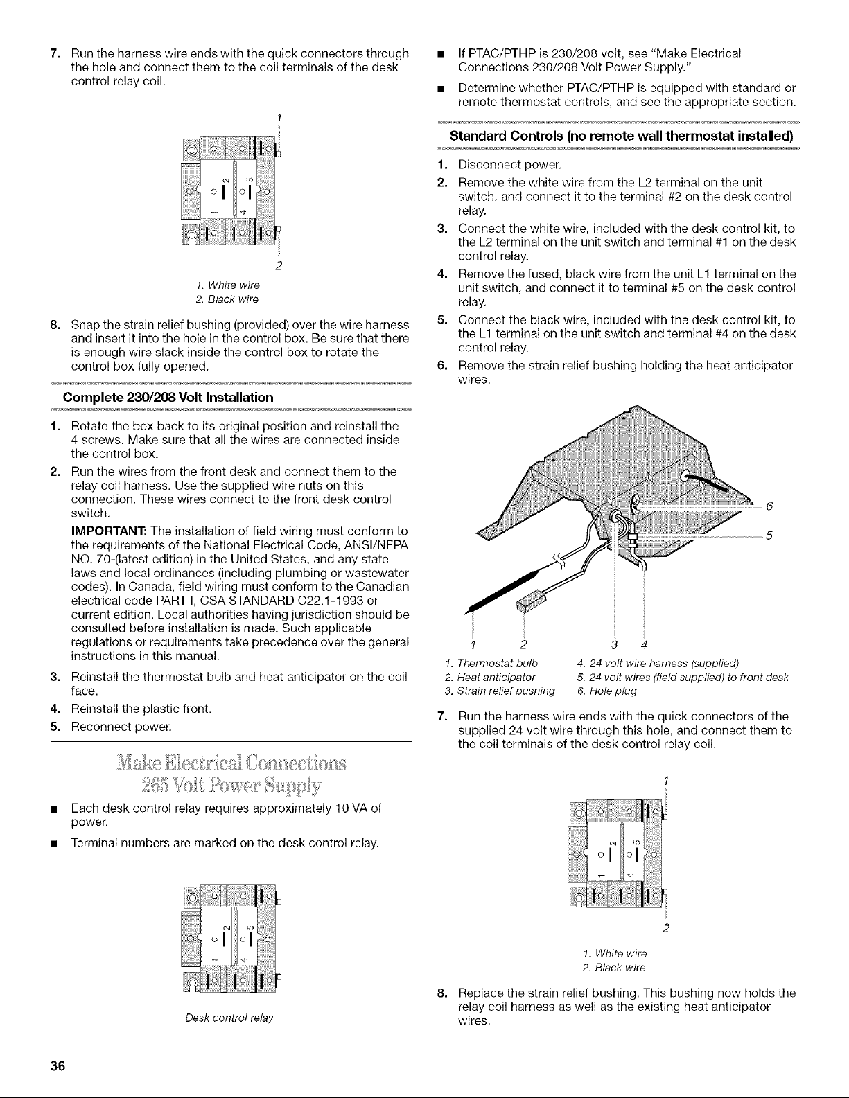
6. Remove the strain relief bushing holding the heat anticipator
wires.
6
5
1 2
1. Thermostat bulb
2. Heat anticipator
3. Strain relief bushing
3 4
4. 24 volt wire harness (supplied)
5. 24 volt wires (field supplied) to front desk
6. Hole plug
7. Run the harness wire ends with the quick connectors of the
supplied 24 volt wire through this hole, and connect them to
the coil terminals of the desk control relay coil.
Desk control relay
8=
1. White wire
2. Black wire
Replace the strain relief bushing. This bushing now holds the
relay coil harness as well as the existing heat anticipator
wires.
36
Loading ...
Loading ...
Loading ...