Loading ...
Loading ...
Loading ...
8. Reattach the PTAC/PTHP front cover using the thumbscrews
removed earlier.
9. Replace all subbase covers.
10. Reconnect power.
230/208 volt installation with field-supplied NEC approved
receptacle and disconnect switch accessory
Parts needed
• NEC approved receptacle
• Black, white or red, and green wires
1. Disconnect power.
2. Route incoming power supply wires into the subbase behind
the front cover.
3=
Connect the incoming L1 black wire and the incoming
L2 white or red wire to one side of the disconnect switch.
Connect a field-supplied black wire and field-supplied white
or red wire to the other side of the disconnect switch. These
2 wires must be long enough to reach the receptacle.
Z
3
2 4
5
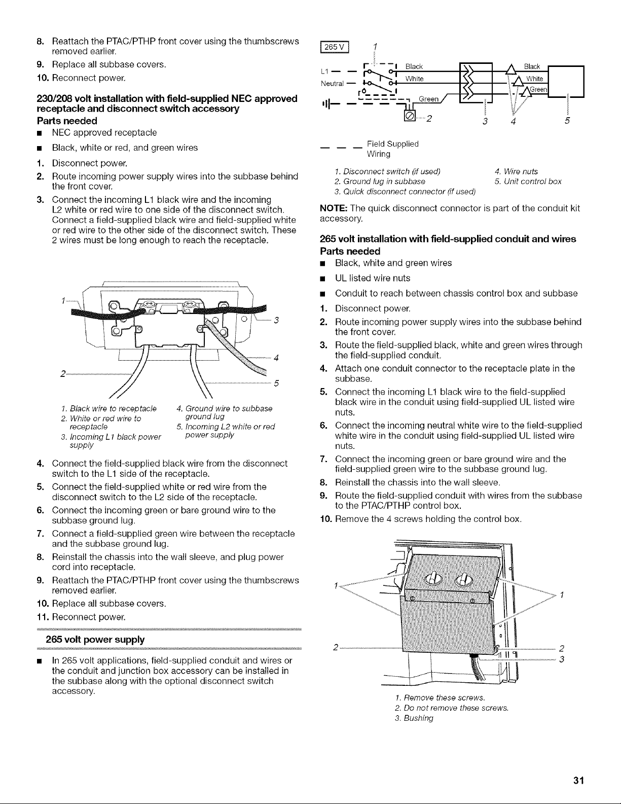
1. Black wire to receptacle
2. White or red wire to
receptacle
3. Incoming L1 black power
supply
4. Ground wire to subbase
ground lug
5. Incoming L2 white or red
power supply
4. Connect the field-supplied black wire from the disconnect
switch to the L1 side of the receptacle.
5. Connect the field-supplied white or red wire from the
disconnect switch to the L2 side of the receptacle.
6. Connect the incoming green or bare ground wire to the
subbase ground lug.
7. Connect a field-supplied green wire between the receptacle
and the subbase ground lug.
8. Reinstall the chassis into the wall sleeve, and plug power
cord into receptacle.
9. Reattach the PTAC/PTHP front cover using the thumbscrews
removed earlier.
10. Replace all subbase covers.
11. Reconnect power.
265 volt power supply
• In 265 volt applications, field-supplied conduit and wires or
the conduit and junction box accessory can be installed in
the subbase along with the optional disconnect switch
accessory.
r ';' - -i Black
L1 b_oOl ,,_ _,_!i_ , I
Neutral -- r .... II White
'II-- !_jj
_ 2
3 4 5
Field Supplied
Wiring
1. Disconnect switch (if used) 4. Wire nuts
2. Ground lug in subbase 5. Unit control box
3. Quick disconnect connector (if used)
NOTE: The quick disconnect connector is part of the conduit kit
accessory.
265 volt installation with field-supplied conduit and wires
Parts needed
• Black, white and green wires
• ULlisted wire nuts
• Conduit to reach between chassis control box and subbase
1. Disconnect power.
2. Route incoming power supply wires into the subbase behind
the front cover.
3. Route the field-supplied black, white and green wires through
the field-supplied conduit.
4. Attach one conduit connector to the receptacle plate in the
subbase.
5. Connect the incoming L1 black wire to the field-supplied
black wire in the conduit using field-supplied UL listed wire
nuts.
6. Connect the incoming neutral white wire to the field-supplied
white wire in the conduit using field-supplied UL listed wire
nuts.
7. Connect the incoming green or bare ground wire and the
field-supplied green wire to the subbase ground lug.
8. Reinstall the chassis into the wall sleeve.
9. Route the field-supplied conduit with wires from the subbase
to the PTAC/PTHP control box.
10. Remove the 4 screws holding the control box.
!. Remove these screws.
2. Do not remove these screws.
3. Bushing
31
Loading ...
Loading ...
Loading ...