Loading ...
Loading ...
Loading ...
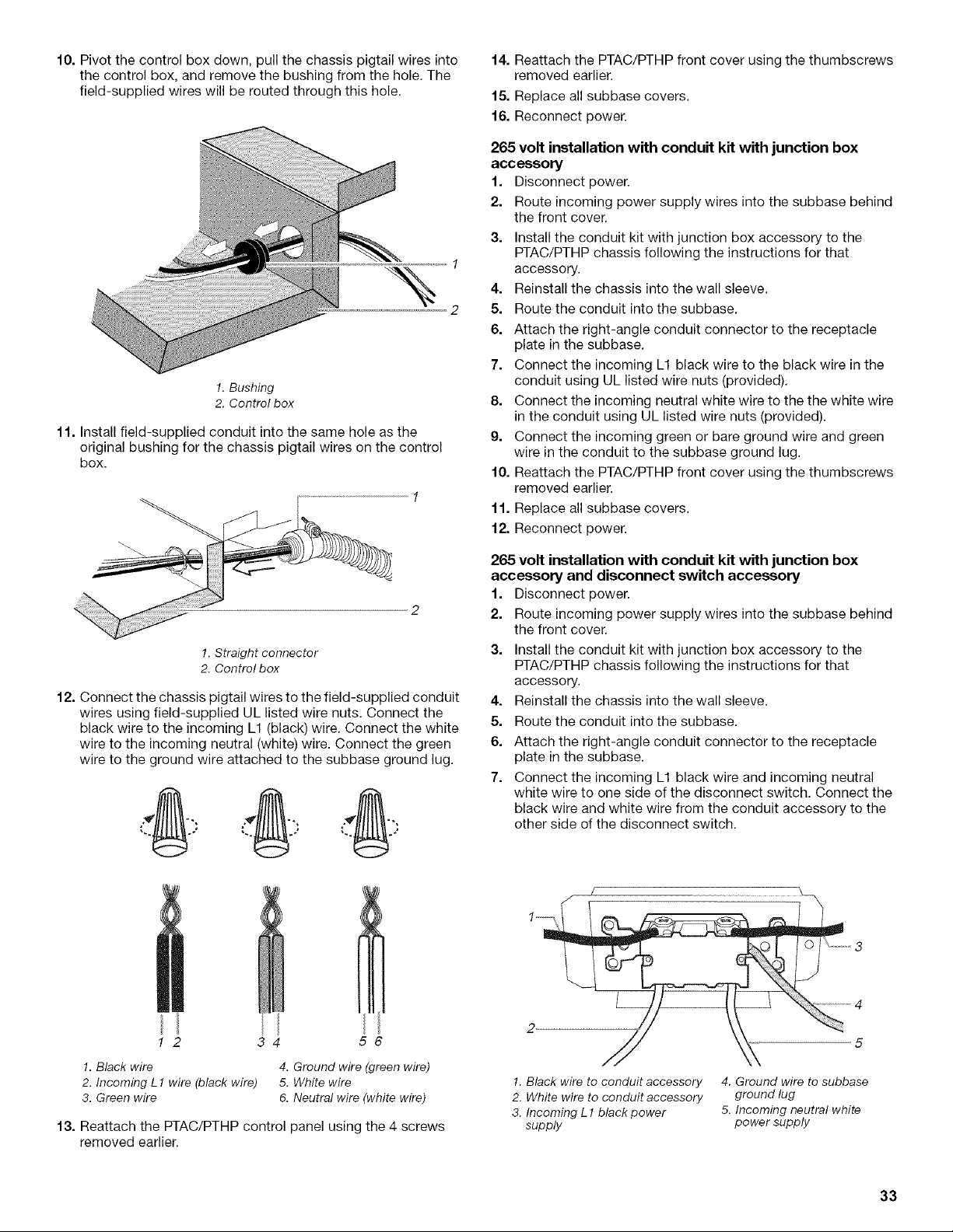
10. Pivot the control box down, pull the chassis pigtail wires into
the control box, and remove the bushing from the hole. The
field-supplied wires will be routed through this hole.
!. Bushing
2. Control box
11. Install field-supplied conduit into the same hole as the
original bushing for the chassis pigtail wires on the control
box.
1. Straight connector
2. Control box
12. Connect the chassis pigtail wires to the field-supplied conduit 4.
wires using field-supplied UL listed wire nuts. Connect the
black wire to the incoming L1 (black) wire. Connect the white 5.
wire to the incoming neutral (white) wire. Connect the green 6.
wire to the ground wire attached to the subbase ground lug.
1 2
14. Reattach the PTAC/PTHP front cover using the thumbscrews
removed earlier.
15. Replace all subbase covers.
16. Reconnect power.
265 volt installation with conduit kit with junction box
accessory
1. Disconnect power.
2. Route incoming power supply wires into the subbase behind
the front cover.
3. Install the conduit kit with junction box accessory to the
PTAC/PTHP chassis following the instructions for that
accessory.
4. Reinstall the chassis into the wall sleeve.
5. Route the conduit into the subbase.
6. Attach the right-angle conduit connector to the receptacle
plate in the subbase.
7. Connect the incoming L1 black wire to the black wire in the
conduit using UL listed wire nuts (provided).
8. Connect the incoming neutral white wire to the the white wire
in the conduit using UL listed wire nuts (provided).
9. Connect the incoming green or bare ground wire and green
wire in the conduit to the subbase ground lug.
10. Reattach the PTAC/PTHP front cover using the thumbscrews
removed earlier.
11. Replace all subbase covers.
12. Reconnect power.
265 volt installation with conduit kit with junction box
accessory and disconnect switch accessory
1. Disconnect power.
2. Route incoming power supply wires into the subbase behind
the front cover.
3. Install the conduit kit with junction box accessory to the
PTAC/PTHP chassis following the instructions for that
accessory.
Reinstall the chassis into the wall sleeve.
7.
Route the conduit into the subbase.
Attach the right-angle conduit connector to the receptacle
plate in the subbase.
Connect the incoming L1 black wire and incoming neutral
white wire to one side of the disconnect switch. Connect the
black wire and white wire from the conduit accessory to the
other side of the disconnect switch.
3 56
1. Black wire 4. Ground wire (green wire)
2. Incoming L1 wire (black wire) 5. White wire
3. Green wire 6. Neutral wire (white wire)
13. Reattach the PTAC/PTHP control panel using the 4 screws
removed earlier.
1 \ ...............3
1. Black wire to conduit accessory
2. White wire to conduit accessory
3. Incoming L 1 black power
supply
4. Ground wire to subbase
ground lug
5. Incoming neutral white
power supply
33
Loading ...
Loading ...
Loading ...