Loading ...
Loading ...
Loading ...
Direct Wired Models
Electrical Shock Hazard
Disconnect power before servicing.
Replace all parts and panels before operating.
Failure to do so can result in death or electrical shock.
• Field wiring connections for direct-wired models can be done
in one of 2 ways:
• Using field-supplied conduit and wires
• Using the Conduit with Junction Box Kit accessory, See
"Required Parts, Accessories and Options."
Field Wiring Connections
1. Disconnect power.
2. Remove the PTAC/PTHP front cover using the thumbscrews.
3. Route the incoming power supply through suitable conduit to
the PTAC/PTHP control box.
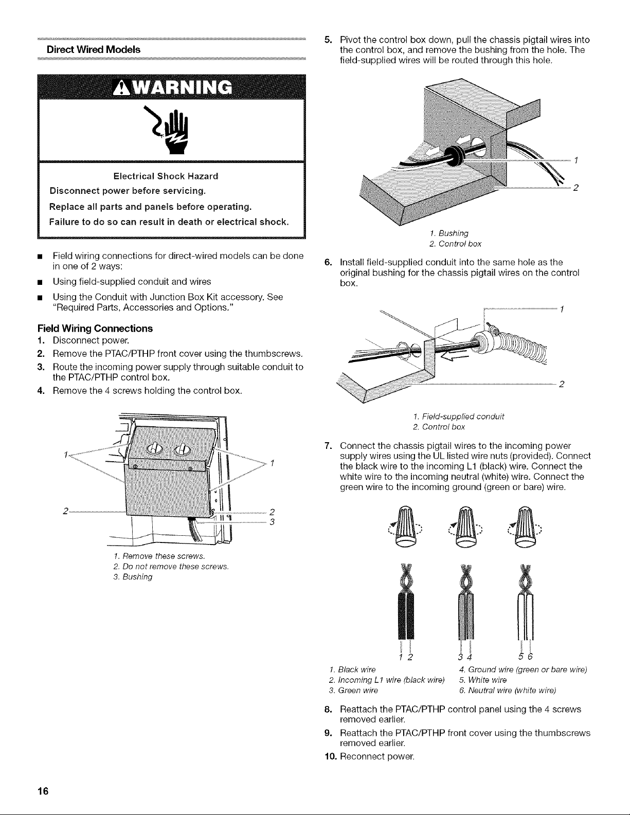
4. Remove the 4 screws holding the control box.
!. Remove these screws.
2. Do not remove these screws.
3. Bushing
5. Pivot the control box down, pull the chassis pigtail wires into
the control box, and remove the bushing from the hole. The
field-supplied wires will be routed through this hole.
1
%
2
6=
!. Bushing
2. Control box
Install field-supplied conduit into the same hole as the
original bushing for the chassis pigtail wires on the control
box.
1. Field-supplied conduit
2. Control box
7.
Connect the chassis pigtail wires to the incoming power
supply wires using the UL listed wire nuts (provided). Connect
the black wire to the incoming L1 (black) wire. Connect the
white wire to the incoming neutral (white) wire. Connect the
green wire to the incoming ground (green or bare) wire.
1. Black wire
2. Incoming L 1 wire (black wire)
3. Green wire
4. Ground wire (green or bare wire)
5. White wire
6. Neutral wire (white wire)
8. Reattach the PTAC/PTHP control panel using the 4 screws
removed earlier.
9. Reattach the PTAC/PTHP front cover using the thumbscrews
removed earlier.
10. Reconnect power.
16
Loading ...
Loading ...
Loading ...