Loading ...
Loading ...
Loading ...
7. Reattach disconnect switch cover assembly to subbase.
8. Attach a 12 A.W.G. ground wire to the ground terminal on the
disconnect switch and to the ground lug in the subbase.
Power supply wires will be connected during subbase
installation.
9. Replace all covers.
f
!. Ground wire to subbase ground lug
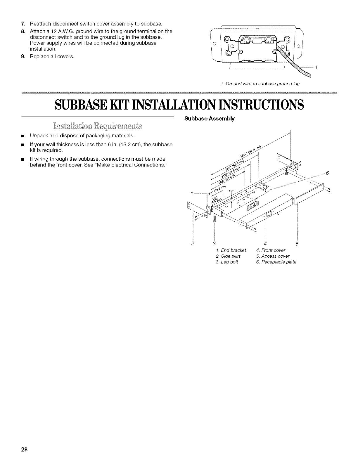
SUBBASE KITINSTALLATIONINSTRUCTIONS
Subbase Assembly
• Unpack and dispose of packaging materials.
• If your wall thickness is less than 6 in. (15.2 cm), the subbase
kit is required.
• If wiring through the subbase, connections must be made
behind the front cover. See "Make Electrical Connections."
3 4 5
!. End bracket 4. Front cover
2. Side skirt 5. Access cover
3. Leg bolt 6. Receptacle plate
28
Loading ...
Loading ...
Loading ...