Loading ...
Loading ...
Loading ...
8,
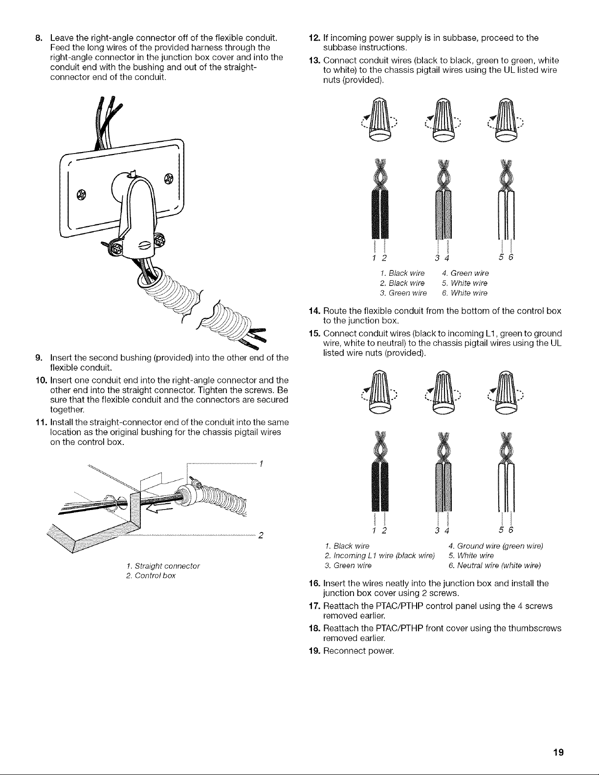
Leave the right-angle connector off of the flexible conduit.
Feed the long wires of the provided harness through the
right-angle connector in the junction box cover and into the
conduit end with the bushing and out of the straight-
connector end of the conduit.
9. Insert the second bushing (provided) into the other end of the
flexible conduit.
10. Insert one conduit end into the right-angle connector and the
other end into the straight connector. Tighten the screws. Be
sure that the flexible conduit and the connectors are secured
together.
11. Install the straight-connector end of the conduit into the same
location as the original bushing for the chassis pigtail wires
on the control box.
!. Straight connector
2. Control box
12. If incoming power supply is in subbase, proceed to the
subbase instructions.
13. Connect conduit wires (black to black, green to green, white
to white) to the chassis pigtail wires using the UL listed wire
nuts (provided).
I 2 34 56
1. Black wire 4. Green wire
2. Black wire 5. White wire
3. Green wire 6. White wire
14. Route the flexible conduit from the bottom of the control box
to the junction box.
15. Connect conduit wires (black to incoming L1, green to ground
wire, white to neutral) to the chassis pigtail wires using the UL
listed wire nuts (provided).
I 2 34 56
1. Black wire 4. Ground wire (green wire)
2. Incoming L 1 wire (black wire) 5. White wire
3. Green wire 6. Neutral wire (white wire)
16. Insert the wires neatly into the junction box and install the
junction box cover using 2 screws.
17. Reattach the PTAC/PTHP control panel using the 4 screws
removed earlier.
18. Reattach the PTAC/PTHP front cover using the thumbscrews
removed earlier.
19. Reconnect power.
19
Loading ...
Loading ...
Loading ...