
Loading ...
Loading ...
Loading ...
42
75D2525
DVM Series Direct Vent Gas Fireplace
• Easy Access Function Operation and System Conguration
• Operation Conrmation/Fault Diagnostic Indications (LED/
Buzzer)
• ON/OFF/HI/Med/Low Operation
• Optional Wall Mounting
• Electronic Ignition
• Pilot Lockout safety feature
• Electric Power Regeneration from Thermopile to save battery
• 6-hour Automatic Shut Down Option
• Convenient NG/LP Gas Type Conversion
• Standing Pilot/Intermittent pilot Conversion
• Previous settings Restoration Ability (Memory Off)
• Uninterrupted Operation During Power Outage (Automatic
Battery Backup)
• ON/OFF RF Remote Receiver
• Optional Transmitter Learn Capability
• Easy Snap-on Design
• Embedded Compact 120 VAC Adapter with Auto Battery
Back up Feature
• Remote Controlled 3-step Blower, Lighting, and On/Off Auxiliary AC Outputs
TSFSC TSTSC TSMSC RTSC RMSC
Three Flame Height Settings X X X X X
Low battery Indication for Transmitter X X X X X
Child Proof Lock-out X X X X X
LCD Backlight X X X X X
Security Codes 16 X X X X X
Countdown 6 hr Timer X X X -- --
Standard Thermostatic Control Mode X X -- X --
Smart Mode
®
Thermostat (Auto Flame & Blower Modulation) X X -- -- --
Three Brightness Settings for Lights X -- -- -- --
Three Speed Control for Blower X -- -- -- --
On/Off Auxiliary X -- -- -- --
Programmable Timer to turn blower on and off X -- -- -- --
The Command Center uses four (4) "AA" batteries as back up for power outages. The system can operate for ap-
proximately six (6) months on battery power.
1. Press down the battery door tabs and pull out to remove battery door.
2. Install the batteries as indicated on Command Center.
3. Close battery door by snapping in place.
4. When the four (4) batteries are installed the system will operate without power.
5. The batteries should be replaced when the LED indicates low battery or at least once a year.
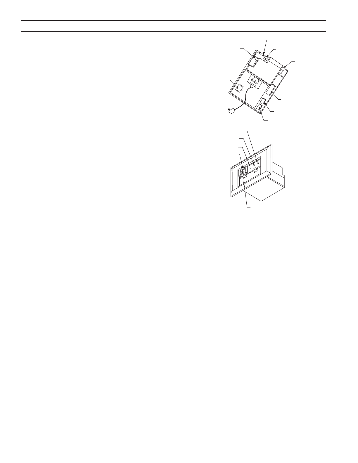
RF Receiver
ON/OFF
NG/LP
Conversion
To Thermopile
To Sensor
To Sparker
To Command Center
To Stepper Motor
To Valve
Battery Door
Master Switch
ON
LED
OFF
Figure 54 -
Signature Command System Components
6 V A/C
Adapter
Loading ...
Loading ...
Loading ...