Loading ...
Loading ...
Loading ...
20
75D2525
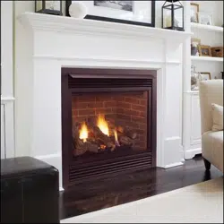
DVM Series Direct Vent Gas Fireplace
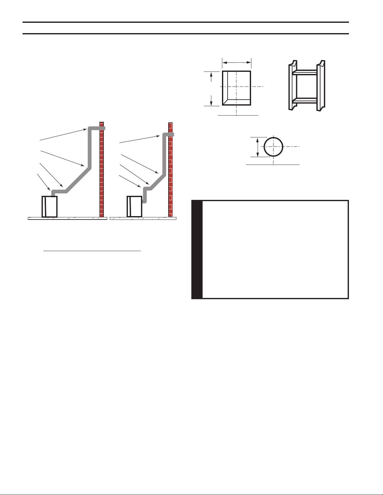
Elbow 1 = 90°
Elbow 2 = 45°
Elbow 3 = 45°
Elbow 4 = 90°
Total Angular Variation = 270°
Figure 24 -
Maximum Elbow Usage
1
2
3
4
1
2
3
4
• The maximum number of 45° elbows permitted per side
wall installation is two (2). These elbows can be installed
in either the vertical or horizontal run.
• For each 45° elbow installed in the horizontal run, the
length of the horizontal run MUST be reduced by 18"
(457 mm). This does not apply if the 45° elbows are
installed on the vertical part of the vent system.
• The maximum number of elbow degrees in a system is
270°. Figure 24
1. Locate and cut the vent opening in the wall. For com-
bustible walls rst frame in opening.
Cut a 12Z\x"H x 10Z\x" W
(318 x 267 mm) hole through the interior wall.
Cut a 10Z\x"H x 10Z\x"
W (267 x 267 mm) square hole through the exterior
wall frame. Figure 25
Hole opening should be 8Z\x"
(216 mm) in diameter.
2. The center of the hole should align with the center line
of the horizontal rigid vent pipe end. Allow 1/4" minimum
rise per foot. Figure 25
B\,
B\,
1. Locate and cut the vent opening in the wall. For com-
bustible walls rst frame in opening.
Cut a 11Z\x"H x 9Z\x" W
(292 x 241 mm) hole through the interior wall.
Cut a 9Z\x"H x 9Z\x"W (241
x 241 mm) square hole through the exterior wall frame.
Figure 26
Hole opening should be 7Z\x"
(190 mm) in diameter.
2. The center of the hole should align with the center line
of the horizontal rigid vent pipe end. Allow 1/4" minimum
rise per foot. Figure 26
Figure 25 -
Exterior Wall Framing Dimensions
10Z\x"
(267 mm)
10Z\x"
(267 mm)
VO584-100
8Z\x"
(216 mm)
Loading ...
Loading ...
Loading ...