Loading ...
Loading ...
Loading ...
11
75D2525
DVM Series Direct Vent Gas Fireplace
The appliance is shipped as a rear vent unit. If the installa-
tion layout requires the unit to be a top vent conguration
the appliance can be converted by following the steps
below.
When removing and retting the plates and adapter be
sure the associated gaskets are undamaged and retted
as required.
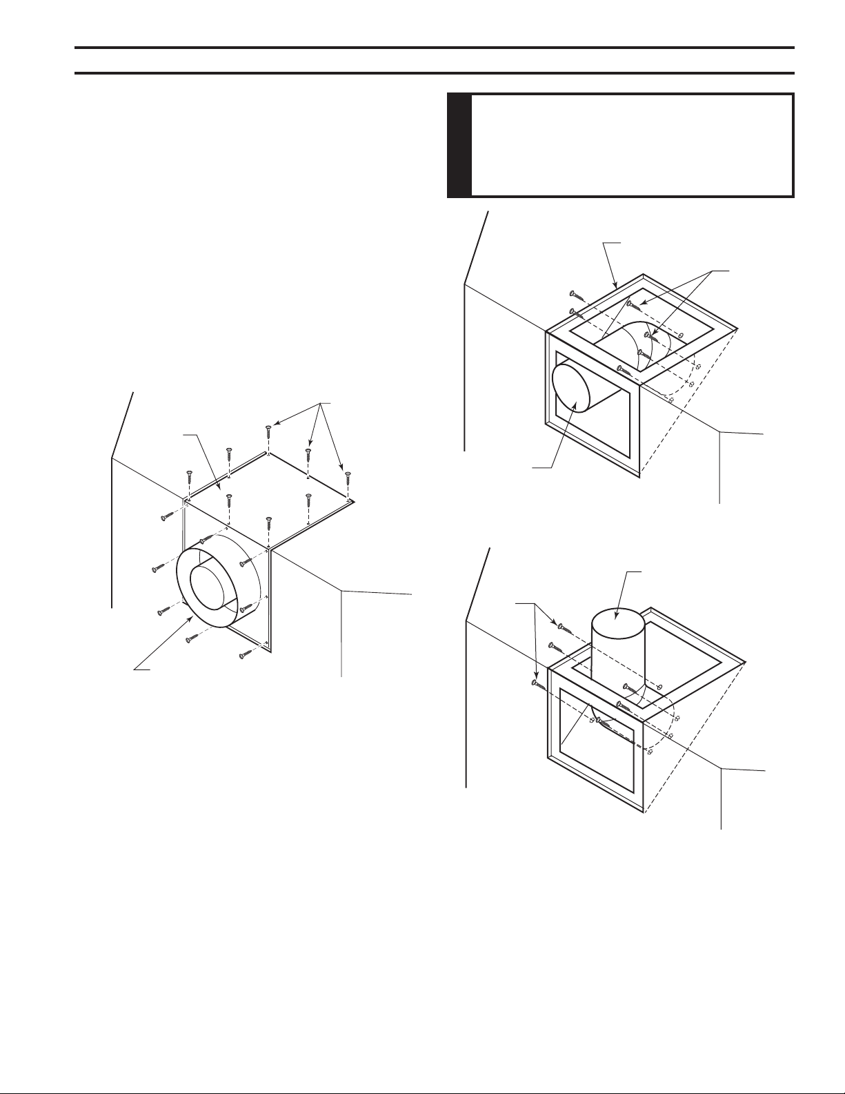
1. Remove the eight (8) screws securing the ue pipe
adapter to the replace body. Figure 7
2. Set the ue pipe adapter aside, complete with the
gasket. Do not damage the gaskets as the adapter and
gasket must be retted.
3. Remove the eight (8) screws securing the ue pipe cover
to the top of the intake box and remove the cover and
gasket. Figure 7
Flue Pipe
Cover
Flue Pipe
Adapter
Screws
FP1991
4. Remove six (6) screws securing the ue pipe to the
back of the intake box and remove the pipe and gasket.
Figure 8
5. Replace ue pipe to top of rebox. Ensure the gasket is
in place and undamaged. Secure with six (6) screws.
Figure 9
6. Place the ue pipe cover and gasket removed in step
3 over the ue opening in bottom of the intake box.
Figure 7 -
Remove 16 Screws from Flue Pipe
Adapter and Flue Pipe Cover
Figure 8 -
Remove Flue Pipe
Screws
Flue Cover
Flue Pipe
FP1992
Figure 9 -
Attach Flue Pipe to Top
Vent Congurations
Flue Pipe
Screws
FP1993
7. Ret the ue pipe adapter and gasket to the top of re-
place. Secure the adapter with six (6) screws removed
in Step 1.
Loading ...
Loading ...
Loading ...