Title 24
CFR, Part 3280 or Standard for Installation in Mobile
Homes. CAN/CSA Z3-240MH.
Installation & Operating
Instructions
75D2525 1/11 Rev. 7

2
75D2525
DVM Series Direct Vent Gas Fireplace
High Elevations .......................................................5
Gas Pressures ........................................................5
Gas Specications & Orice Size ...........................5
Before You Start ......................................................7
Fireplace Framing ...................................................7
Fireplace Location ...................................................8
Installation Precautions .........................................12
Installation Clearances ..........................................13
Installation Planning ..............................................14
Horizontal and Vertical Termination.......................14
Termination Location .............................................15
Termination Clearances ........................................16
How to Use a Vent Graph .....................................16
Rear Wall Vent Installation ...................................17
Horizontal with Vertical Rise (Through-the-Wall)
Installation & Applications ...................................18
Below Grade Installation .......................................21
Vertical Through-the-Roof Installation ...................22
Installation for Vertical Termination .......................23
Flat Ceiling Installation ..........................................23
Check Gas Type....................................................28
Gas Pipe Installation .............................................29
Electrical Wiring ....................................................30
Remote Wall Mounted Switch ...............................31
What To Do If You Smell Gas ................................32
Lighting Pilot for the First Time .............................32
Lighting Pilot - Millivolt ..........................................33
Lighting Burner - Millivolt .......................................34
To Turn Off Gas - Millivolt ......................................34
Junction Box Wiring ..............................................36
Command Center Wall Installation ........................36
Wall Switch Installation .........................................36
Signature Command System Wiring Diagram ......37
BLOTSDVC Command Blower .............................38
BLOTSDV Automatic Thermostat Blower .............39
Operating Instructions ...........................................41
To Turn Off Gas to Appliance ................................41
Burner, Pilot and Control Compartment ................48
Burner Flame ........................................................48
Vent System ..........................................................49
Glass Door ............................................................49
Logs ......................................................................49
Rock Wool ............................................................49
Standing Pilot Ignition ...........................................50
Signature Command System ................................52
Firebox Components .............................................53
Standing Pilot - Millivolt Control ............................54
Signature Command System ................................56
Logs ......................................................................58
Additional Accessories .........................................59
Vent Components for 4" x 6
B\," ..............................60
Vent Components for 5" x 8" .................................61
Vent Components for 4" x 7" .................................62
3
75D2525
DVM Series Direct Vent Gas Fireplace
4. Never install the replace
• in a recreational vehicle
• where curtains, furniture, clothing, or other am-
mable objects are less than 42" from the front, top,
or sides of the replace
• in high trafc areas
• in windy or drafty areas
5.
6.
7. Do not modify replace under any circumstances. Any
parts removed for servicing must be replaced prior to
operating replace.
8. Turn replace off and let cool before servicing, install-
ing, or repairing. Only a qualied service person should
install, service, or repair the replace. Have burner
system inspected annually by a qualified service
person.
9. You must keep control compartments, burners, and
circulating air passages clean. More frequent cleaning
may be needed due to excessive lint and dust from
carpeting, bedding material, pet hair, etc. Turn off the
gas valve and pilot light before cleaning replace.
10. Have venting system inspected annually by a qualied
service person. If needed, have venting system cleaned
or repaired. Refer to Cleaning and Maintenance, Page
48.
11. Keep the area around your replace clear of combus-
tible materials, gasoline, and other ammable vapor and
liquids. Do not run replace where these are used or
stored. Do not place items such as clothing or decora-
tions on or around replace.
12. Do not use this replace to cook food or burn paper or
other objects.
13. Never place anything on top of replace.
This replace is a vented product. This replace must be
properly installed by a qualied service person. The glass
door must be properly seated and sealed. If this unit is not
properly installed by a qualied service person with glass
door properly seated and sealed, combustion leakage can
occur.
Early signs of carbon
monoxide poisoning are similar to the u with headaches,
dizziness and/or nausea. If you have these signs, the re-
place may not have been installed properly. Get fresh air
at once! Have the replace inspected and serviced by a
qualied service person. Some people are more affected
by carbon monoxide than others. These include pregnant
women, people with heart or lung disease or anemia,
those under the inuence of alcohol, and those at high
altitudes.
Propane/LP gas and natural gas are both odorless. An
odor-making agent is added to each of these gases. The
odor helps you detect a gas leak. However, the odor added
to these gases can fade. Gas may be present even though
no odor exists.
Make certain you read and understand all warnings. Keep
this manual for reference. It is your guide to safe and proper
operation of this replace.
1. This appliance is only for use with the type of gas
indicated on the rating plate. This appliance is not
convertible for use with other gases unless a certied
kit is used.
2. For propane/LP replace, do not place propane/LP
supply tank(s) inside any structure. Locate propane/
LP supply tank(s) outdoors. To prevent performance
problems, do not use propane/LP fuel tank of less than
100 lbs. capacity.
3. If you smell gas
• shut off gas supply.
• do not try to light any appliance.
• do not touch any electrical switch; do not use any
phone in your building .
• immediately call your gas supplier from a neighbor’s
phone. Follow the gas supplier’s instructions.
Please leave these instructions with the appliance.
Please retain these instructions for future reference
.
4
75D2525
DVM Series Direct Vent Gas Fireplace
14. Do not use any solid fuels (wood, coal, paper, card-
board, etc.) in this replace. Use only the gas type
indicated on rating plate.
15. This appliance, when installed, must be electrically
grounded in accordance with local codes or in the
absence of local codes, with the National Electrical
Code, ANSI/NFPA 70, or the Canadian Electrical Code,
CSA C22.1.
16. Do not obstruct the ow of combustion and ventilation
air in any way. Provide adequate clearances around
air openings into the combustion chamber along with
adequate accessibility clearance for servicing and
proper operation.
17. When the appliance is installed directly on carpeting,
tile or other combustible material other than wood oor-
ing, you must set appliance on a metal or wood panel
or hearth pad extending the full width and depth of the
appliance.
18. Do not use replace if any part has been under or
exposed to, water. Immediately call a qualied service
technician to inspect the appliance and replace any
part of the control system and any gas control which
has been submerged in water.
19. Do not operate replace if any log is broken.
20. Do not use a blower insert, heat exchanger insert, or
any other accessory not approved for use with this
replace.
21. Do not operate the replace with glass door removed,
cracked, or broken.
22.
Direct Vent type appliances draw all combustion air from outside of the dwelling through the vent pipe.
These appliances have been tested by CSA and found to comply with the established standards for DIRECT VENT
GAS FIREPLACE HEATERS in the USA and Canada as follows:
TESTED TO: ANSI Z21.88b-2008/CSA 2.33b-2008 STANDARDS
A manufactured home (USA only) or mobile home OEM installation must conform with the Manufactured Home Con-
struction and Safety Standard, or when such a standard is not applicable, the
, or
.
It is normal for replaces fabricated of steel
to give off some expansion and/or contraction
noises during the start up or cool down cycle.
Similar noises are found with your furnace heat
exchanger or car engine.
It is not unusual for gas replace to give off
some odor the rst time it is burned. This is due
to the manufacturing process.
It is recommended that you burn your replace
for at least ten (10) hours the rst time you use
it. Place the fan switch in the “OFF” position
during this time.
WARNING
!
HOT GLASS WILL
CAUSE BURNS.
DO NOT TOUCH GLASS
UNTIL COOLED.
NEVER ALLOW CHILDREN
TO TOUCH GLASS.
5
75D2525
DVM Series Direct Vent Gas Fireplace
• This appliance has been certied for use with either
natural or propane gas. See appropriate data plates.
• This appliance is not for use with solid fuels.
• The appliance is approved for bedroom or bedsitting
room installations.
• The appliance must be installed in accordance with local
codes if any. If none exist use the current installation
code. ANSI Z223.1/NFPA 54 in the USA, CSA B149 in
Canada.
• This appliance is mobile home approved.
• The appliance must be properly connected to a venting
system.
• The appliance is not approved for closet or recessed
installations.
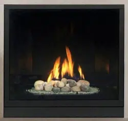
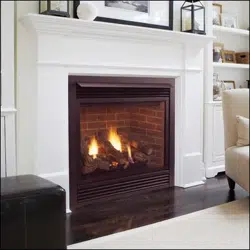
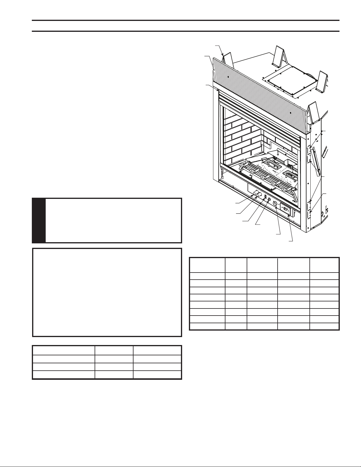
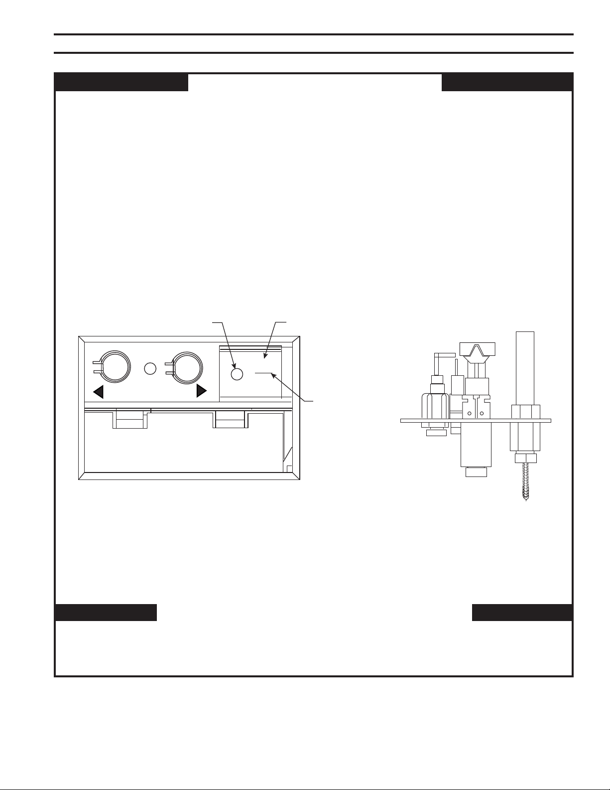
Off/Pilot/On Knob
Optional Remote Receiver
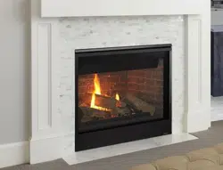
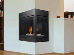
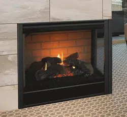
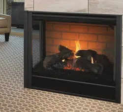
Figure 1 -
500DVM and 600DVM Fireplace
(Millivolt Unit Shown — Also Available with
Signature Command System)
Hi/Lo Knob
Blower Control
On/Off/RS Switch
Ignitor
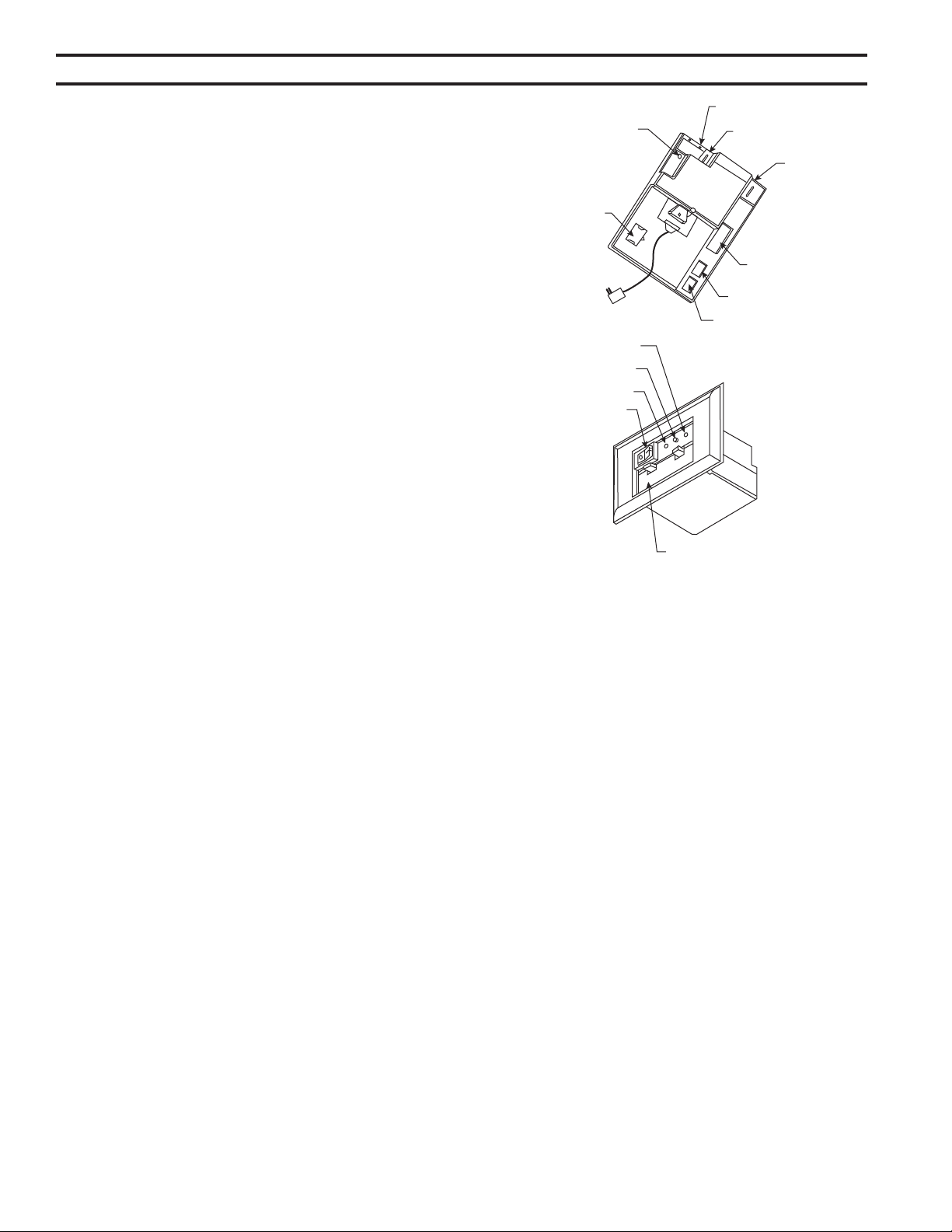
1/2"
Nailing
Flange
5/8"
Nailing
Flange
1/2"
Nailing
Flange
Eyebrow
Insulation
Board
Standoff
FP2407
Input ratings are shown in BTU per hour and are certied
without deration for elevations up to 4,500 feet (1,370
m) above sea level.
For elevations above 4,500 feet (1,370 m) in USA,
installations must be in accordance with the current
ANSI Z223.1/NFPA 54 and/or local codes having juris-
diction.
In Canada, please consult provincial and/or local authori-
ties having jurisdiction for installations at elevations
above 4,500 feet (1,370 m).
Natural Propane (LP)
Inlet Minimum 4.0” w.c. 11.0” w.c.
Inlet Maximum 14.0” w.c. 13.0” w.c.
Manifold Pressure 3.5” w.c. 10.0” w.c.
500DVMNV Nat. 30,000 21,500 7/64"
500DVMPV LP 30,000 23,500 #51
500DVMNSC Nat. 30,000 21,500 7/64"
500DVMPSC LP 30,000 23.500 #51
600DVMNV Nat. 32,000 22,000 #34
600DVMPV LP 32,000 26,000 #50
600DVMNSC Nat. 32,000 22,000 #34
600DVMPSC LP 32,000 26,000 #50
6
75D2525
DVM Series Direct Vent Gas Fireplace
A
B
G
H
I
K
D
L
M
N
R
S - Min. Rough Opening Width
T
U
1/2”
5/8”
1/2”
5/8”
V
V
W
Min. Rough
Opening
Depth
1/2” or 5/8”
E
F
256O”
(64 mm)
5”
2”
Min. Rough
Opening
Height
J
C
O
P
Q
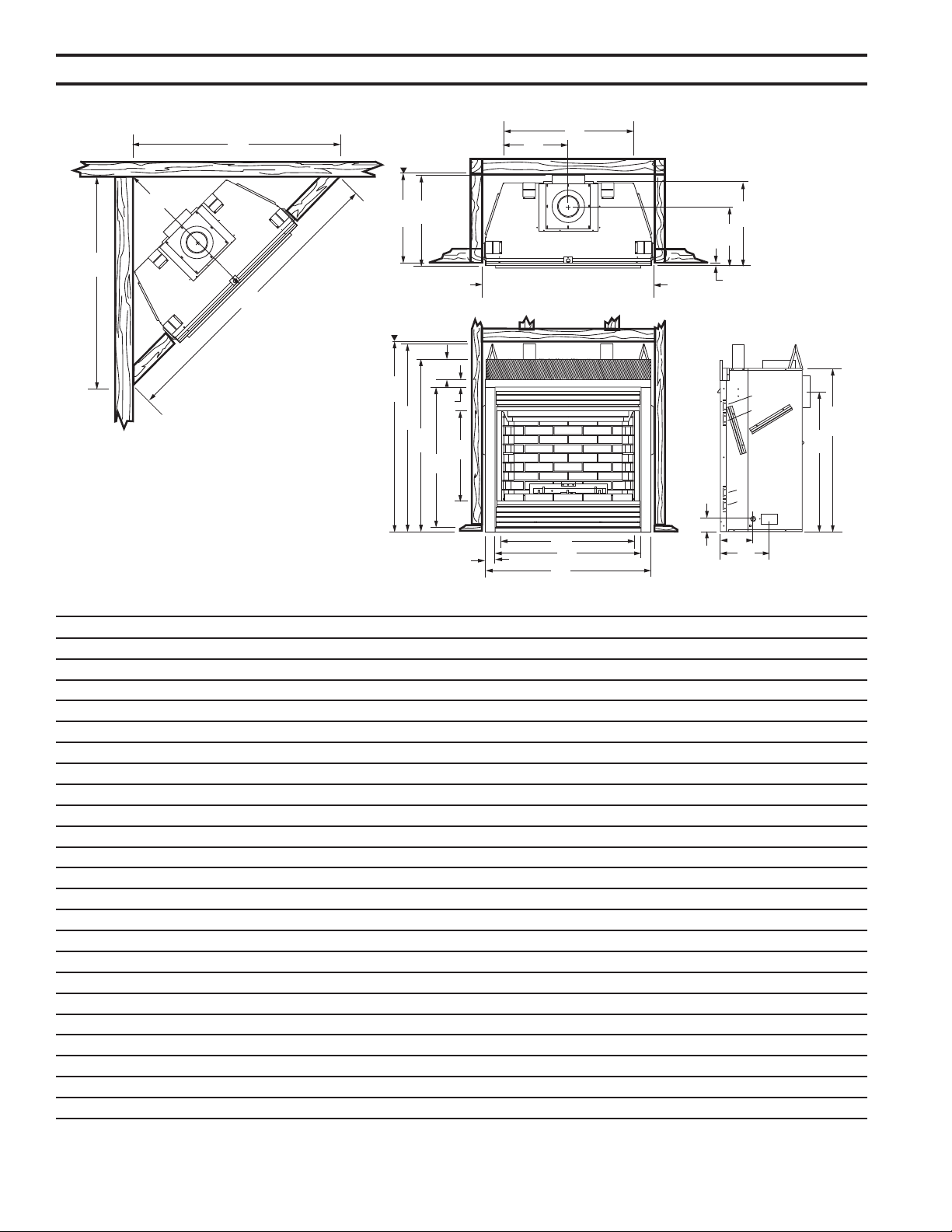
A 41" (1041 mm) 47" (1194 mm)
B 46B\zn" (1176 mm) 46B\zn" (1176 mm)
C 40C\," (1026 mm) 40C\," (1026 mm)
D 32C\zn" (818 mm) 38C\zn" (970 mm)
E 36" (914 mm) 42" (1067 mm)
F 32ZB\zn" (837 mm) 38ZB\zn" (989 mm)
G 42M\zn" (1079 mm) 42M\zn" (1079 mm)
H 34Z\x" (876 mm) 34Z\x" (876 mm)
I 23C\zn" (589 mm) 23C\zn" (589 mm)
J 34B\," (880 mm) 34B\," (880 mm)
K 16Z\," (410 mm) 19Z\," (486 mm)
L 14>\zn" (370 mm) 14>\zn" (370 mm)
M 20C\v" (527 mm) 20C\v" (527 mm)
N 22B\zn" (567 mm) 22B\zn" (567 mm)
O 3C\," (86 mm) 3C\," (86 mm)
P 7C\," (187 mm) 7C\," (187 mm)
Q 12Z\zn" (306 mm) 12Z\zn" (306 mm)
R 46Z\x" (1181 mm) 46Z\x" (1181 mm)
S 42Z\zn" (1068 mm) 42Z\zn" (1068 mm)
T 20C\," (516 mm) 20C\," (516 mm)
U 73Z\x" (1867 mm) 79Z\x" (2019 mm)
V 52" (1321 mm) 56Z\v" (1429 mm)
W 36C\v" (934 mm) 39C\v" (1010 mm)
Figure 2 -
Fireplace & Framing Dimensions
7
75D2525
DVM Series Direct Vent Gas Fireplace
Read this homeowner manual thoroughly and follow all
instructions carefully. Inspect all contents for shipping
damage and immediately inform your dealer if any damage
is found. Do not install any unit with damaged, incomplete,
or substitute parts. Check your packing list to verify that
all listed parts have been received. You should have the
following:
• Fireplace (Firebox and Burner System)
• Log Set • Eyebrow
• Rock Wool • Front Floor Brick Assembly
• White Toggle Switch • Fasteners
• Switch Cover Plate • Restrictor Plate/Disc (2)
• Noncombustible Panel
• Phillips Screwdriver • Framing Materials
• Hammer • Wall Finishing Materials
• Saw and/or saber saw • Level
• Measuring Tape • Pliers
• Electric Drill and Bits • Square
• Pipe Wrench • Tee Joint
• Caulking Material (noncombustible)
• Fireplace Surround Material (noncombustible)
• Piping Complying with Local Codes
• Pipe Sealant Approved for use with Propane/LPG
(Resistant to sulfur compounds)
Firebox framing can be built before or after the appliance
is set in place. Refer to Figure 2 for rebox dimensions and
framing. Construct rebox framing following Figure 2 for
your specic installation requirements. The framing head-
ers may rest on the top of the rebox standoffs.
The rebox may be installed directly on a combustible oor
or raised on a platform of an appropriate height. When
the rebox is installed directly on carpeting, tile, or other
combustible material, other than wood ooring, the rebox
shall be installed on a metal or wood panel extending the
full width and depth of the enclosure.
8
75D2525
DVM Series Direct Vent Gas Fireplace
Plan for the installation of your appliance. This includes determining where the unit is to be installed,
the vent conguration to be used, framing and nishing details, and whether any optional accessories
(i.e. blower, wall switch, or remote control) are desired. Consult your local building code agency to
ensure compliance with local codes, including permits and inspections.
The following factors should be taken into consideration:
• Clearance to side-wall, ceiling, woodwork, and windows. Minimum clearances to combustibles
• This replace may be installed along a wall, across a corner, or use an exterior chase. Refer to
Figure 3 for suggested locations.
• Location should be out of high trafc areas and away from furniture and draperies due to heat
from appliance.
• Never obstruct the front opening of the replace.
• Do install in the vicinity where gasoline or other ammable liquids may be stored.
• Vent pipe routing. See Venting section found in this manual for allowable venting congura-
tions.
• These units can be installed in a bedroom. Refer to the National Fuel Gas Code ANSI Z233.1/
NFPA 54 — (current edition), the Uniform Mechanical Code — (current edition), and Local Build-
ing Codes for specic installation requirements.
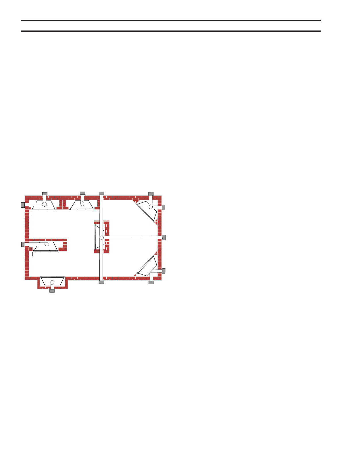
Figure 3 -
Locating Gas Fireplace
** Island (C) and room divider (D) installation is possible as long
as the horizontal portion of vent system (X) does not exceed
20'. Refer to Installing Horizontal Termination Conguration on
Pages 19.
* When you install your replace in (D) room divider or (E) at
on wall corner positions (Y), a minimum of 6" clearance must
be maintained from perpendicular wall and front of replace.
Y
E
A
B
C
D
F
Y
B
X
A Flat on Wall
B Cross Corner
C Island**
D Room Divider*
E Flat on Wall Corner*
F Chase Installation
Y 4" Minimum
9
75D2525
DVM Series Direct Vent Gas Fireplace
72”
(1829 mm)
Minimum
12”
(305 mm)
Minimum
6”
(152 mm)
Min.
12”
(305 mm)
Maximum Depth
Ceiling
Side Wall
Combustible
Mantel
FP2408
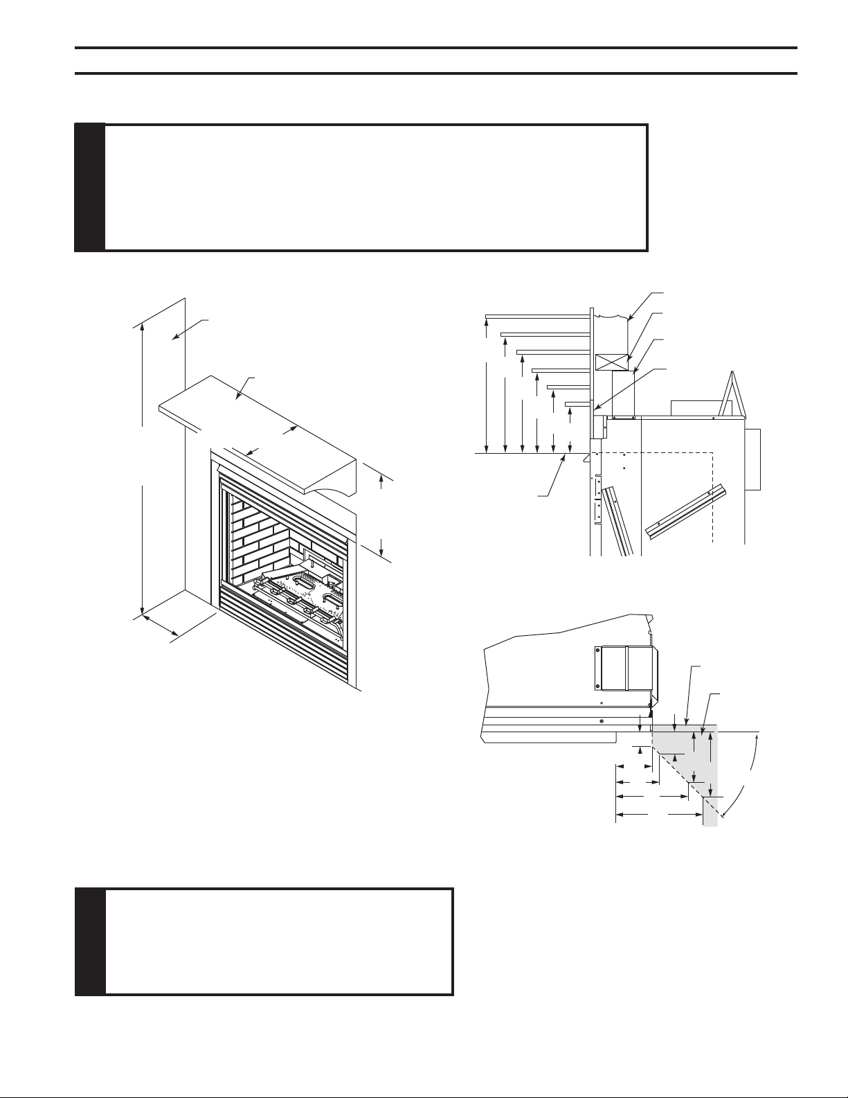
Figure 4 -
Ceiling and Side Wall Clearances
12”
10”
8”
6”
4”
256O”
12"
106M”
956O”
856M”
7”
6”
Top of Fireplace
Opening
Stud
Header
Standoff
Insulation
Board
FP2409
45°
1”
256O”
3”
5”
6”
56O”
56O”
56O”
Finish Wall
Combustible
Material Area
FP2410
Figure 5 -
Mantel Clearances
The combustible area above the facing must not protrude
more than 1/2" from the facing. If it does, it is considered a mantel
and must meet the mantel requirements listed in this manual.
10
75D2525
DVM Series Direct Vent Gas Fireplace
Any remote wiring (i.e. remote control, wall switch, and optional fan) must be done prior to
nal nishing to avoid costly reconstruction.
Only noncombustible materials (i.e. brick, tile, slate, steel, or other materials with a UL re rating
of Zero) may be used to cover the black surface of the appliance. A 300°F minimum adhesive may
be used to attach facing materials to the black surface. If joints between the nished wall and the
replace surround are sealed, a 300°F minimum sealant material (General Electric RTV103 or
equivalent) must be used.
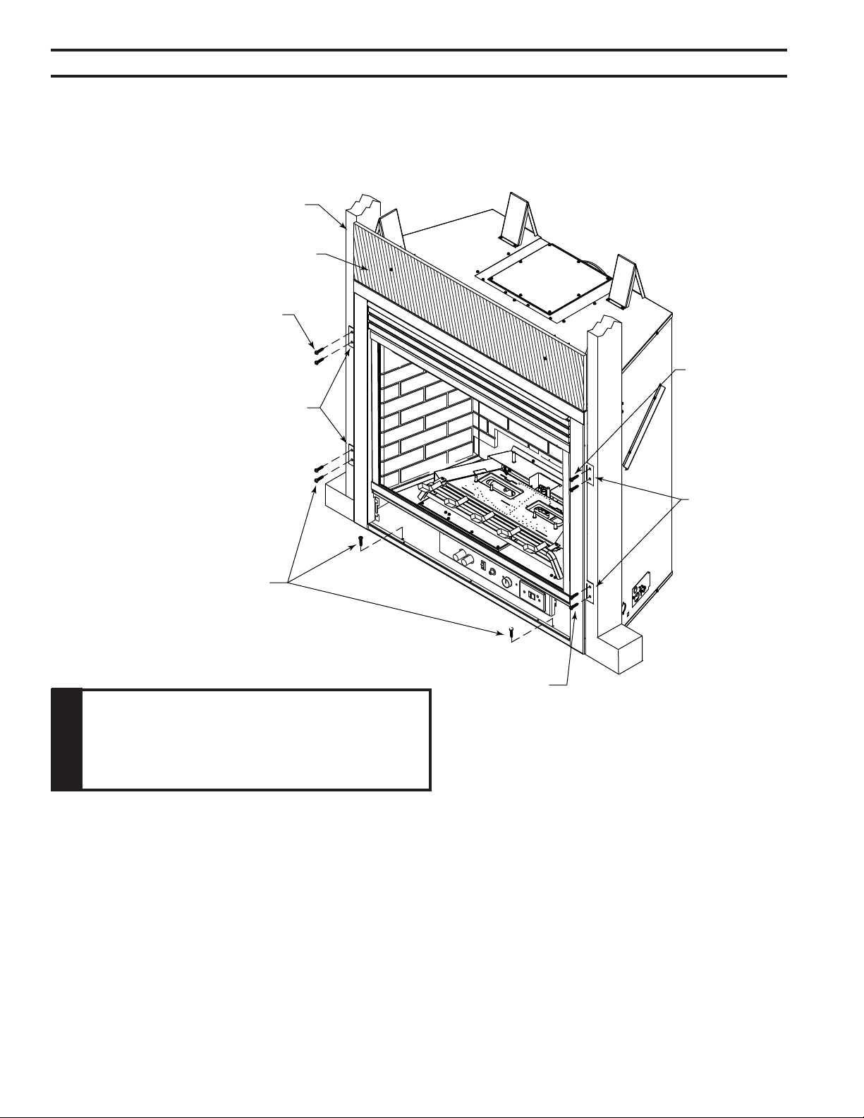
The replace must be secured to the oor and/or to framing studs as shown in Figure 6 . Use two
(2) wood screws or masonry/ concrete screws to secure replace to the oor. Use four (4) screws
to attach replace to framing. The side brackets or nailing anges are designed to accommodate
two thickness of wall boards (1/2" or 5/8").
Figure 6 -
Secure Fireplace to Floor and Framing Studs
Screws
Screws
Screws
Screws
Nail Flange
Nail
Flange
Framing
FP2411
Insulation Board
11
75D2525
DVM Series Direct Vent Gas Fireplace
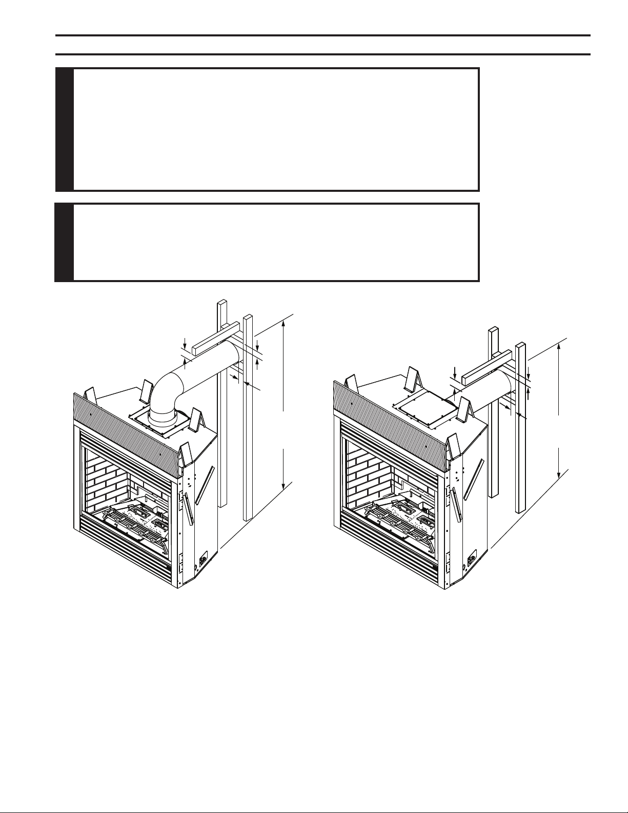
The appliance is shipped as a rear vent unit. If the installa-
tion layout requires the unit to be a top vent conguration
the appliance can be converted by following the steps
below.
When removing and retting the plates and adapter be
sure the associated gaskets are undamaged and retted
as required.
1. Remove the eight (8) screws securing the ue pipe
adapter to the replace body. Figure 7
2. Set the ue pipe adapter aside, complete with the
gasket. Do not damage the gaskets as the adapter and
gasket must be retted.
3. Remove the eight (8) screws securing the ue pipe cover
to the top of the intake box and remove the cover and
gasket. Figure 7
Flue Pipe
Cover
Flue Pipe
Adapter
Screws
FP1991
4. Remove six (6) screws securing the ue pipe to the
back of the intake box and remove the pipe and gasket.
Figure 8
5. Replace ue pipe to top of rebox. Ensure the gasket is
in place and undamaged. Secure with six (6) screws.
Figure 9
6. Place the ue pipe cover and gasket removed in step
3 over the ue opening in bottom of the intake box.
Figure 7 -
Remove 16 Screws from Flue Pipe
Adapter and Flue Pipe Cover
Figure 8 -
Remove Flue Pipe
Screws
Flue Cover
Flue Pipe
FP1992
Figure 9 -
Attach Flue Pipe to Top
Vent Congurations
Flue Pipe
Screws
FP1993
7. Ret the ue pipe adapter and gasket to the top of re-
place. Secure the adapter with six (6) screws removed
in Step 1.
12
75D2525
DVM Series Direct Vent Gas Fireplace
Consult local building codes before beginning the installation. The installer must make sure to
select the proper vent system for installation. Before installing vent kit, the installer must read
this replace manual and vent kit instructions.
Only a qualied installer/service person should install the venting system. The installer must
follow these safety rules:
• Wear gloves and safety glasses for protection.
• Use extreme caution when using ladders or when on rooftops.
• Be aware of electrical wiring locations in walls and ceilings.
The following actions will void the warranty on your venting system:
• Installation of any damaged venting component.
• Unauthorized modication of the venting system.
• Installation of any component part not manufactured or approved by MHSC
• Installation other than permitted by these instructions.
13
75D2525
DVM Series Direct Vent Gas Fireplace
*3"
**1"
**1"
*3”
**1”
**1”
346”
(880 mm)
4856M”
(1226 mm)
FP2412
Figure 10 -
Combustible Clearances for Vent Pipe
* A minimum of 3" clearance to the top is
required along horizontal length until ue pipe
penetrates outside wall.
** A minimum 1" clearance to combustibles
permitted all around ue at outside wall
Z\x
14
75D2525
DVM Series Direct Vent Gas Fireplace
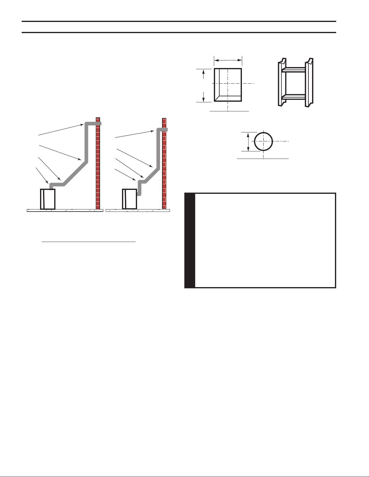
There are two basic types of direct-vent installation:
• Horizontal Termination
• Vertical Termination
It is important to select the proper length of vent pipe for
the type of termination you choose. It is also important to
note the wall thickness.
Select the amount of vertical rise desired. All horizontal run
of venting must have 1/4" rise for every 12" of run towards
the termination below 7Z\x feet of vertical rise. With 7Z\x feet
or more vertical rise off top of replace, the horizontal run
may be level. NEVER run vent piping down.
Horizontal venting which incorporates the twist lock pipe must
be installed on a level plane without an inclining or declining
slope.
You may use up to three 90° elbows in this vent congura-
tion. See Horizontal Termination Congurations on Pages
15 and 16.
Measure the distance from the replace oor to the ceil-
ing. Add the ceiling thickness, the vertical rise in an attic
or second story, and allow for sufcient vent height above
the roof line.
NOTE: You may use two 45° elbows in place of a 90°
elbow. You must follow rise to run ratios when using
45° elbows. The appliance is approved for use with
three 90° elbows maximum or a combination of 90°
and 45° elbows up to a maximum of 270°.
Z\x
For two-story applications, restops are required at each
oor level. If an offset is needed in the attic, additional pipe
and elbows will be required.
You may use a chase with a vent termination with exposed
pipe on the exterior of the house. See Installing Vent
System in a Chase below. If pipe is enclosed in chase, it
is not exposed.
It is very important that the venting system maintain its bal-
ance between the combustion air intake and the ue gas
exhaust. Certain limitations apply to vent congurations
and must be strictly followed.
A chase is a vertical boxlike structure built to enclose
venting that runs along the outside of a building. A chase
is required for such venting.
15
75D2525
DVM Series Direct Vent Gas Fireplace
V
V
V
V
V
V
V
X
X
X
D
E
B
B
B
C
B
M
B
A
J
K
F
L
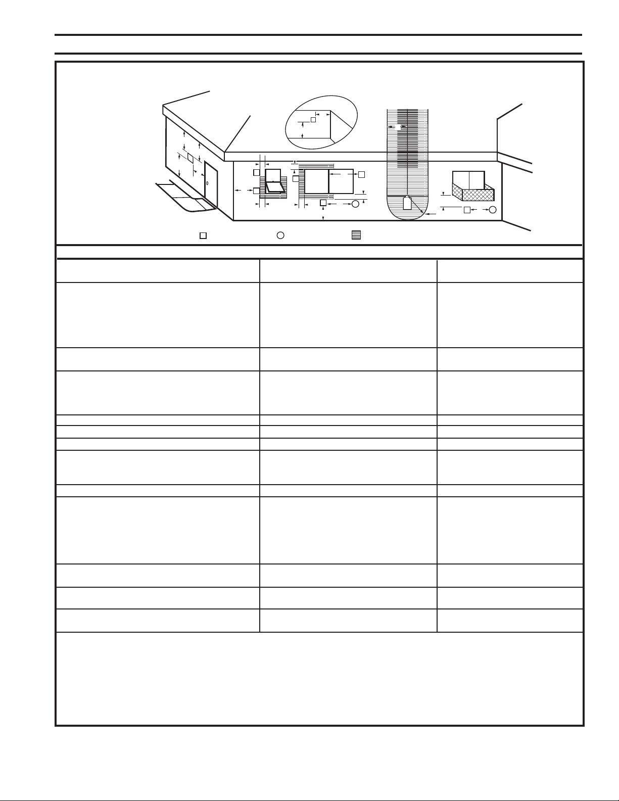
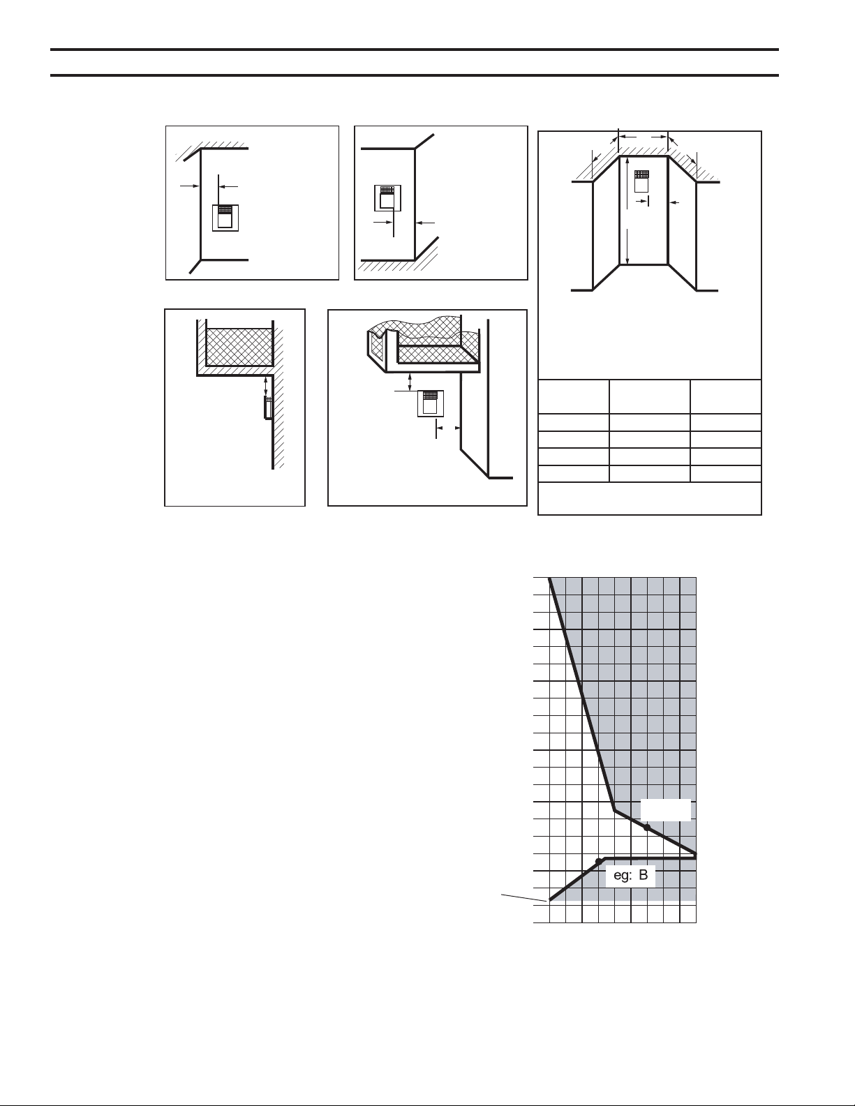
VENT TERMINATION AIR SUPPLY INLET
AREA WHERE TERMINAL IS NOT PERMITTED
H
I
Fixed
Closed
Operable
Operable
Fixed
Closed
V
B
INSIDE
CORNER DETAIL
V
A
G
CFM145a
A = Clearance above grade, veranda, porch, 12” (30 cm) 12” (30 cm)
deck, or balcony
B = Clearance to window or door that may be 6” (15 cm) for appliances 6” (15 cm) for appliances
opened < 10,000BTU/h (3kW), 12” (30 cm) < 10,000 BTU/h (3kW), 9”
for appliances > 10,000 Btuh (3kW) and (23 cm) for appliances > 10,000
< 100,000 BTU/h (30kW), 36” (91 cm) Btuh (3kW) and < 50,000 BTU/h
for appliances > 100,000 BTU/h (30kW) (15kW), 12” (30 cm) for
appliances > 50,000 BTU/h(15kW)
C = Clearance to permanently closed window 12” (305 mm) recommended to 12” (305 mm) recommended to
prevent window condensation prevent window condensation
D = Vertical clearance to ventilated soft located
above the terminal within a horizontal 18” (458 mm) 18” (458 mm)
distance of 2’ (610mm) from the center
line of the terminal
E = Clearance to unventilated soft 12” (305 mm) 12” (305 mm)
F = Clearance to outside corner see next page see next page
G = Clearance to inside corner (see next page) see next page see next page
H = Clearance to each inside of center line 3’ (91 cm) within a height of 15’ (5 m) 3’ (91 cm) within a height of 15’
extended above meter/regulator assembly above the meter/regulator assembly (5 m) above the meter/regulator
assy
I = Clearance to service regulator vent outlet 3’ (91 cm) 3’ (91 cm)
J = Clearance to nonmechanical air supply inlet 6” (15 cm) for appliances < 10,000 6” (15 cm) for appliances
to building or the combustion air inlet to any BTU/h (3kW), 12” (30 cm) for < 10,000 BTU/h (3kW), 9”
other appliances appliances > 10,000 BTU/h (3kW) and (23 cm) for appliances > 10,000
< 100,000 Btuh (30kW), 36” (91 cm) BTU/h (3kW) and < 50,000 BTU/h
for appliances > 100,000 BTU/h (30kW) (15kW), 12” (30 cm) for
appliances > 50,000 BTU/h(15kW)
K = Clearance to a mechanical air supply inlet 6’ (1.83 m) 3’ (91 cm) above if within 10'
(3 m) horizontally
L = Clearance above paved sidewalk or paved 7’ (2.13 m)† 7’ (2.13 m)†
driveway located on public property
M = Clearance under veranda, porch, deck or 12” (30 cm) 12” (30cm)
balcony
1 In accordance with the current CSA-B149 Installation Codes
2 In accordance with the current ANSI Z223.1/NFPA 54 National Fuel
Gas Codes
† A vent shall not terminate directly above a sidewalk or paved
driveway which is located between two single family
dwellings and serves both dwellings
only permitted if veranda, porch, deck or balcony is fully open on a
minimum 2 sides beneath the oor:
NOTE: 1. Local codes or regulations may require different
clearances.
2. The special venting system used on Direct Vent Fireplaces
are certied as part of the appliance, with clearances
tested and approved by the listing agency.
3. MHSC assumes no responsibility for the improper
performance of the appliance when the venting system
does not meet these requirements.
Figure 11 -
Horizontal Vent Termina-
tion Locations
16
75D2525
DVM Series Direct Vent Gas Fireplace
40
38
36
34
32
30
28
26
24
22
20
18
16
14
12
10
8
6
4
2
2 4 6 8 10 12 14 16 18 20
eg: A
346"
from floor
to center
The Vent Graph should be read in conjunction with the
following vent installation instructions to determine the
relationship between the vertical and horizontal dimensions
of the vent system.
1. Determine the height of the center of the horizontal vent
pipe exiting through the outer wall. Using this dimen-
sion on the Sidewall Vent Graph below, locate the point
intersecting with the slanted graph line.
2. From the point of this intersection, draw a vertical line
to the bottom of the graph.
3. Select the indicated dimension, and position the re-
place in accordance with same.
Example A: If the vertical dimension from the oor of
the replace is 11' (3.4 m) the horizontal run to the face
of the outer wall must not exceed 14' (4.3 m).
Example B: If the vertical dimension from the oor
of the unit is 7' (2.14 m), the horizontal run to the
face of the outer wall must not exceed 8' (2.6 m).
Sidewall Vent Graph showing the relationship between
vertical and horizontal dimensions for a Direct Vent
ue system.
Figure 13 -
Rear Wall Venting Graph
Horizontal Dimension From the Outside Face of the Wall
to the Back of the Fireplace
Vertical Dimension From the Floor of Unit to the Center of the
Horizontal Vent Pipe
Dimensions
in Feet
Outside Corner
Inside Corner
Termination Clearances
Termination clearances for buildings with combustible and noncombustible exteriors.
G =
Combustible
6" (152 mm)
Noncombustible
2" (51 mm)
F =
Combustible
6" (152 mm)
Noncombustible
2" (51 mm)
G
Balcony -
with no side wall
M =
Combustible &
Noncombustible
12" (305 mm)
M
Balcony -
with perpendicular side wall
M = 24" (610 mm)
P = 20” (508 mm)
M
F
Alcove Applications*
C
D
C
E
V
V
Combustible &
Noncombustible
V
V
V
E = Min. 6” (152 mm) for
non-vinyl sidewalls
Min. 12” (305 mm) for
vinyl sidewalls
O = 8’ (2.4 m) Min.
O
P
Figure 12 -
Allowable
Venting
584-15
No.
of Caps DMin. CMax.
1 3’ (914 mm) 2 x DActual
2 6’ (1.8 m) 1 x DActual
3 9’ (2.7 m) 2/3 x DActual
4 12’ (3.7 m) 1/2 x DActual
DMin. = # of Termination caps x 3
CMax. = (2 / # termination caps) x DActual
Termination in an alcove space (spaces open only on one side and with an overhang) is permitted with the dimensions specied for vinyl or
non-vinyl siding and softs. 1. There must be a 3’ (914 mm) minimum between termination caps. 2. All mechanical air intakes within 10’ (1 m) of a
termination cap must be a minimum of 3’ (914 mm) below the termination cap. 3. All gravity air intakes within 3’ (914 mm) of a termination cap must
be a minimum of 1’ (305 mm) below the termination cap.
17
75D2525
DVM Series Direct Vent Gas Fireplace
x
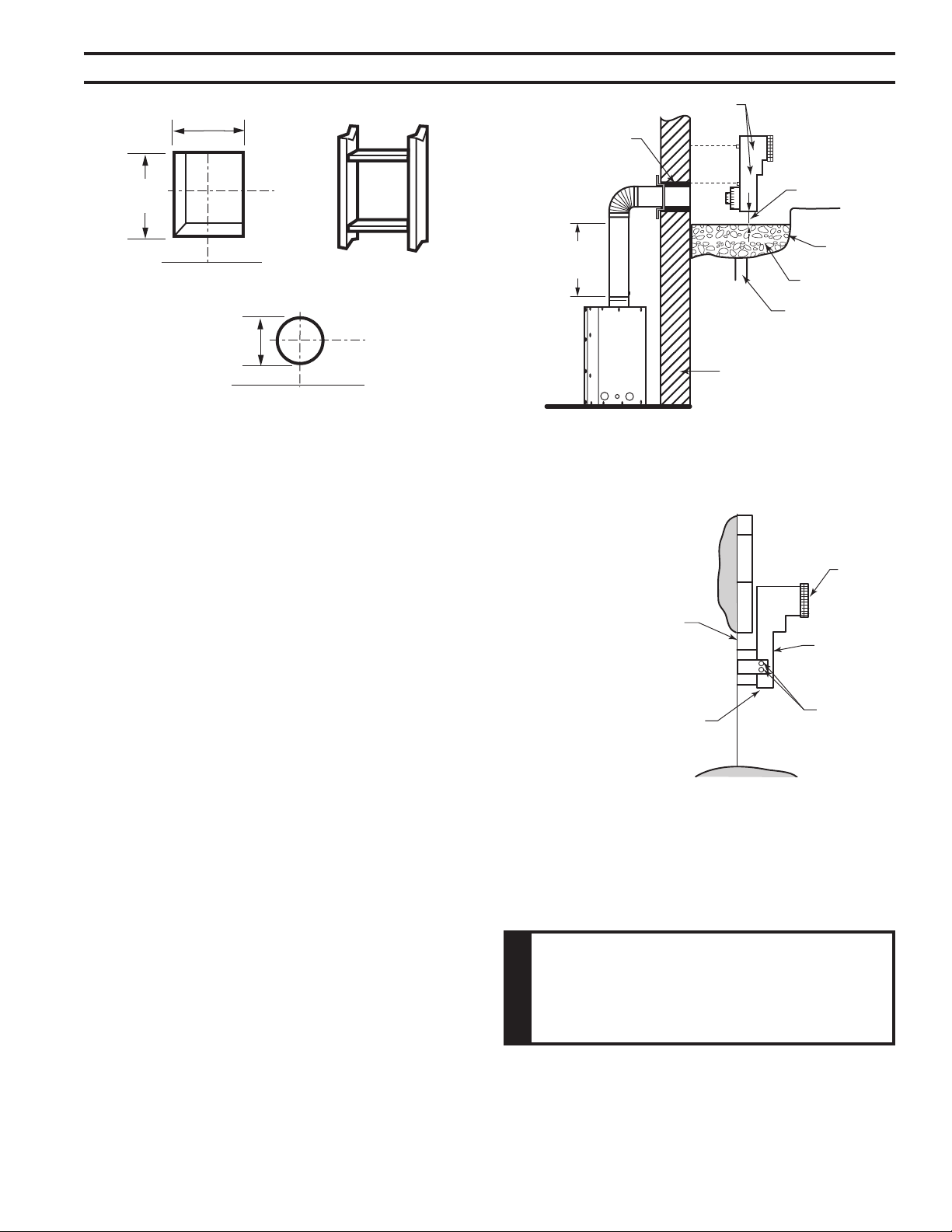
When installed as a rear vent unit this appliance may be
vented directly to a termination located on the rear wall
behind the appliance. Only an MHSC brand termination
is allowed for this application.
• The maximum horizontal distance between the rear
of the appliance and the termination is 20" (508 m).
Figure 14.
• Only one 45° elbow is allowed in these installations.
20"
Maximum
DVR584
Figure 14 -
Rear Vent Application,
Maximum Horizontal Distance
1. Rigid vent pipes and ttings have special twist-lock
connections. Assemble the desired combination of pipe
and elbows to the appliance adapter.
The female ends of the pipes
and ttings have three locking lugs (indentations).
These lugs will slide straight into matching slots on
the male end of adjacent pipes and ttings. Push the
pipe sections together and twist one section clockwise
approximately one-quarter turn until the sections are
fully locked. Figure 15
Female
Locking Lugs
Male Slots
FP1953
2. Refer to the venting and termination instructions for
further instructions.
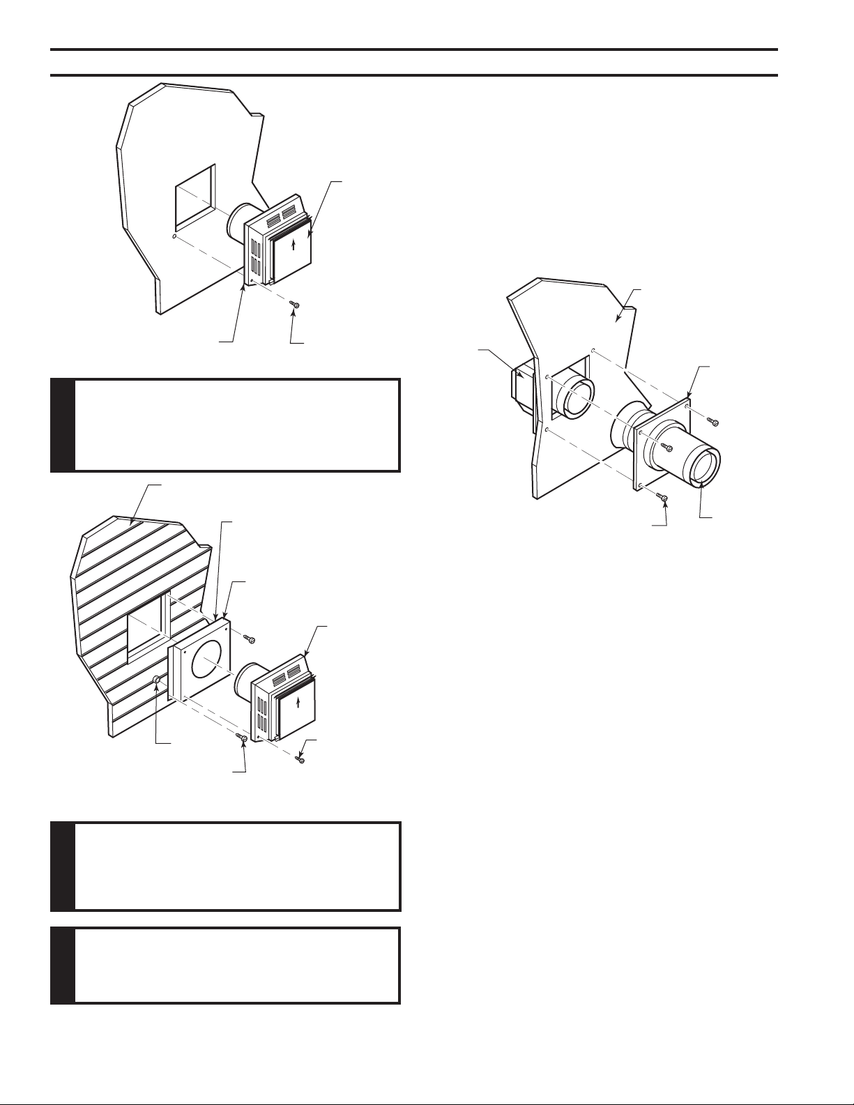
3. Locate and cut the vent opening in the wall. For com-
bustible walls rst frame in opening.
Cut a 12Z\x"H x 10Z\x" W
(318 x 267 mm) hole through the interior wall.
Cut a 10Z\x"H x 10Z\x"W
(267 x 267 mm) square hole through the exterior
wall frame. Figure 16
Hole opening should be 8Z\x"
(216 mm) in diameter.
4. The center of the hole should align with the center line
of the horizontal rigid vent pipe end. Allow 1/4" minimum
rise per foot. Figure 16
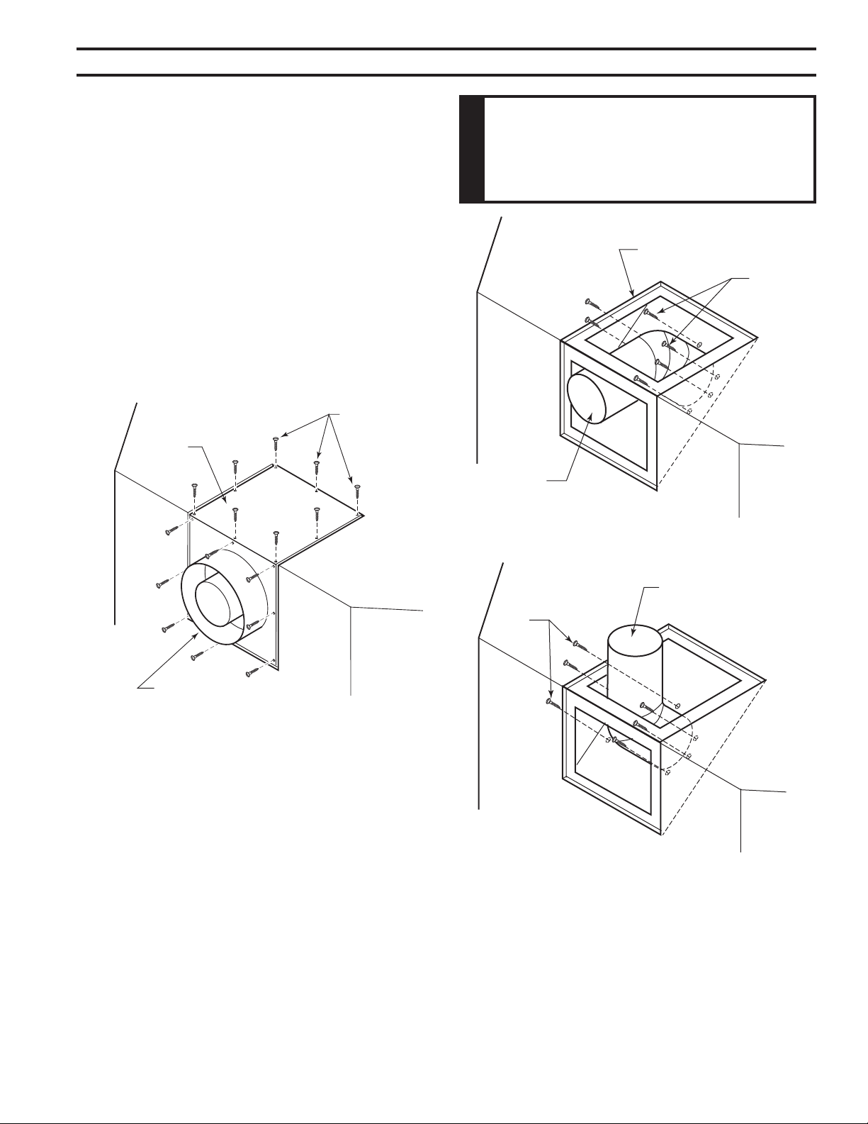
5. Apply a bead of non-hardening mastic around the
outside edge of vent cap. Position the vent cap in the
center of hole on the exterior wall with the word “UP”
on the vent cap facing up. Insure proper clearance of
1" to combustibles is maintained. Attach the vent cap
with four wood screws supplied. Figure 17
Replace the wood screws with appropriate fasteners
for stucco, brick, concrete, or other types of siding.
For vinyl siding, stucco, or wood exterior use vinyl siding
standoffs between vent cap and exterior wall for Simpson
or Selkirk Terminations only. The vinyl siding standoff pre-
vents excessive heat from melting the vinyl siding material.
MHSC Termination does not require standoff. Bolt
the vent cap to the standoff or wall. Apply non-hardening
mastic around outside edge of the standoff instead of the
vent cap assembly. Use wood screws provided to attach
the standoff. Figure 18
Figure 16 -
Exterior Wall Framing Dimensions
10Z\x"
(267 mm)
10Z\x"
(267 mm)
VO584-100
8Z\x"
(216 mm)
18
75D2525
DVM Series Direct Vent Gas Fireplace
HOT
Figure 17 -
Install Horizontal Vent Cap
Vent Cap
Wood Screw
Apply Mastic to
All Sides
FP1955
HOT
Figure 18 -
Installing Vinyl Siding Standoff and Termination
Apply Mastic to All Sides
Cut Vinyl Siding Away to Fit Standoff
or Termination
Wood Screw
Termination
Bolt
Nut
Standoff #1250 or 5DT-VS
(Not Required for MHSC
Termination)
FP1956
Figure 19 -
Connect Vent Cap with Horizontal Vent Pipe
Interior Wall
Surface
Fire Stop
Assembly
Horizontal
Vent Pipe
Screw
Vent Cap
(Horizontal
Termination)
FP1957
The Vent Graph, showing the relationship between vertical
and horizontal side wall venting, will help to determine the
various dimensions allowable. Refer to Page 15.
(Exception: Outside wall with
restop: 1" all around pipes are allowed)
Z\x
When vent termination exits through foundations less than
20" below siding outcrop, the vent pipe must ush up with
the siding.
It is best to locate the replace in such a way that minimizes
the number of offsets and horizontal vent length.
The horizontal vent run refers to the total length of vent
pipe from the ue collar of the replace (or the top of the
transition elbow) to the face of the nished outside wall or
the mounting ange of the termination.
No other manufacturer's termination
is pemitted in this application.
6. Slide the wall thimble over the vent pipe before con-
necting the horizontal run to the vent cap. Figure 19
7. Carefully move the fireplace with vent assembly
attached toward the wall and insert the vent pipe into
the horizontal termination. The pipe overlap should
be a minimum of 1Z\v". Apply silicone to the outer pipe
connection. Fasten all vent connections with screws
provided.
8. Slide the wall thimble against the interior wall surface
and attach with screws. Figure 19
19
75D2525
DVM Series Direct Vent Gas Fireplace
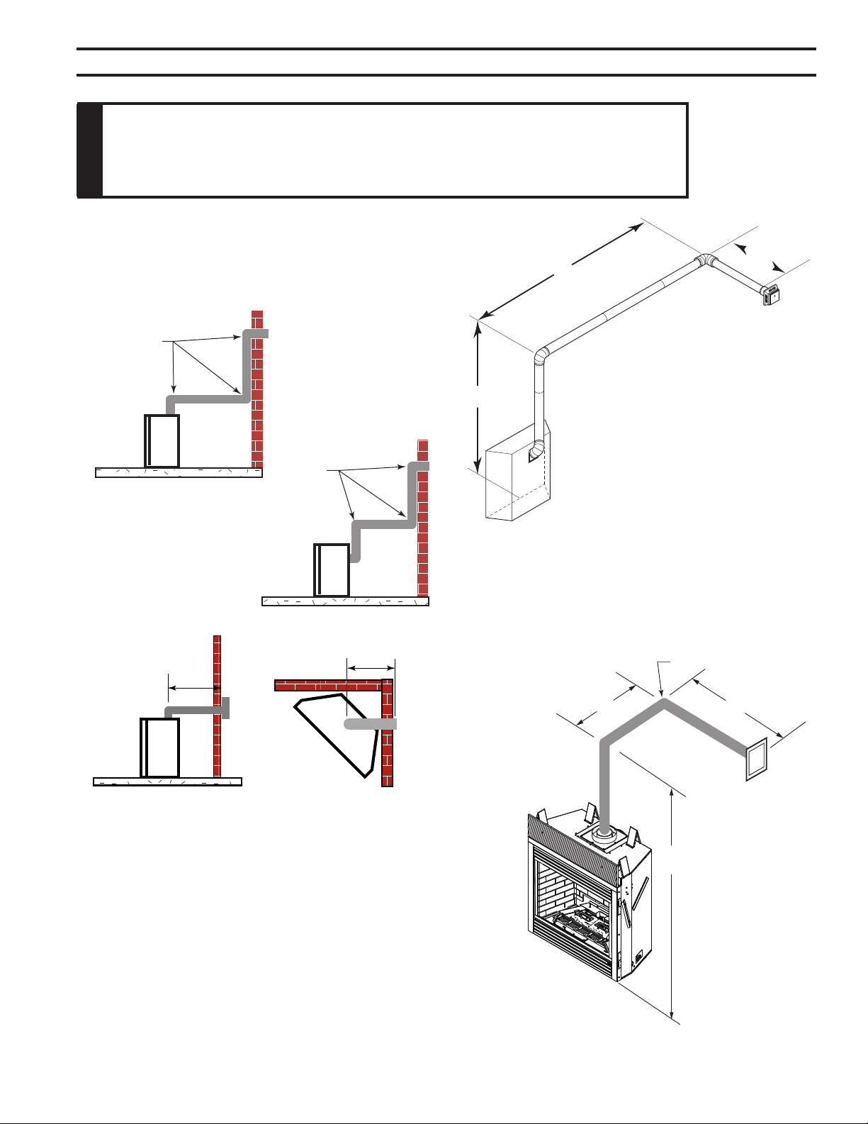
36"
(914 mm)
Max.
36"
(914 mm)
Max.
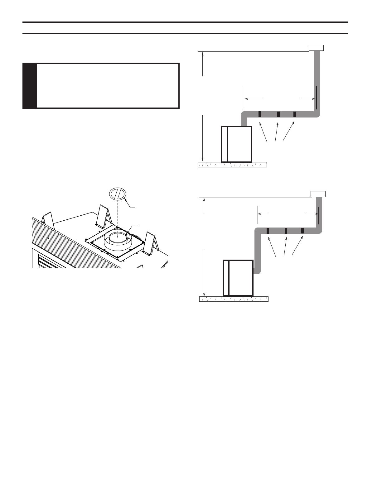
• The maximum number of 90° elbows per side wall
installation is three (3). Figure 20
• If a 90° elbow is tted directly on top of the replace
ange, the maximum horizontal vent run before the ter-
mination or a vertical rise is 36" (914 mm). Figure 21
A: 10’
B: 7’
7’6”
Figure 22 -
Maximum Vent Run with Elbows
Horizontal 90° Elbow = 3' Reduction
FP1959
A + B = 17' Maximum
Figure 20 -
Maximum Three (3) 90° Elbows
Per Installation
3 x 90°
Elbows
3 x 90°
Elbows
FP1176
Figure 21 -
Maximum Horizontal Run with No Rise
FP1177
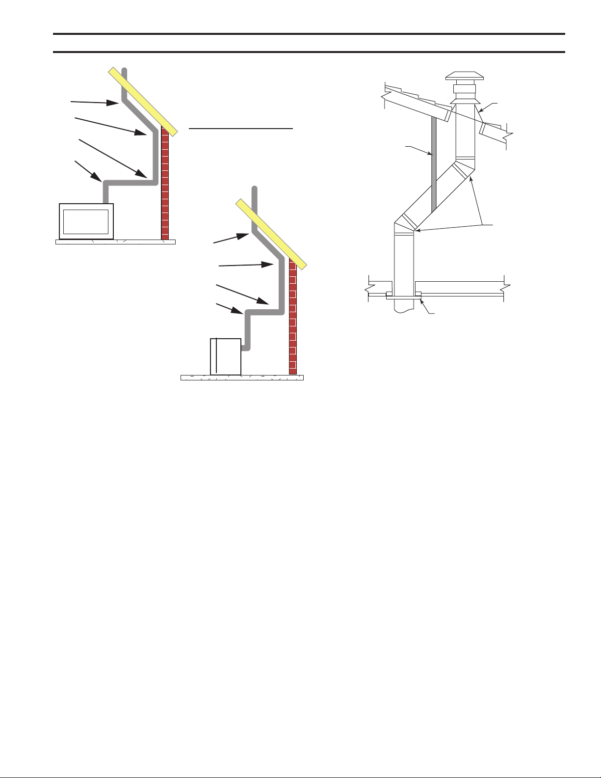
• If a 90° elbow is used in the horizontal vent run (level
height maintained) the horizontal vent length is reduced
by 36" (914 mm) Figure 22. This does not apply if the
90° elbows are used to increase or redirect a vertical
rise. Figure 23
According to the vent graph (Page 15) the
maximum horizontal vent length in a system with a 7.5'
vertical rise is 20’ (6 m) and if a 90° elbow is required in the
horizontal vent it must be reduced to 17' (5.2 m).
In Figures 22 and 23, Dimension A plus B must not be
greater than 17' (5.2 m).
Figure 23 -
Horizontal Run Reduction
A
B
7’6”
90°
FP2413
20
75D2525
DVM Series Direct Vent Gas Fireplace
Elbow 1 = 90°
Elbow 2 = 45°
Elbow 3 = 45°
Elbow 4 = 90°
Total Angular Variation = 270°
Figure 24 -
Maximum Elbow Usage
1
2
3
4
1
2
3
4
• The maximum number of 45° elbows permitted per side
wall installation is two (2). These elbows can be installed
in either the vertical or horizontal run.
• For each 45° elbow installed in the horizontal run, the
length of the horizontal run MUST be reduced by 18"
(457 mm). This does not apply if the 45° elbows are
installed on the vertical part of the vent system.
• The maximum number of elbow degrees in a system is
270°. Figure 24
1. Locate and cut the vent opening in the wall. For com-
bustible walls rst frame in opening.
Cut a 12Z\x"H x 10Z\x" W
(318 x 267 mm) hole through the interior wall.
Cut a 10Z\x"H x 10Z\x"
W (267 x 267 mm) square hole through the exterior
wall frame. Figure 25
Hole opening should be 8Z\x"
(216 mm) in diameter.
2. The center of the hole should align with the center line
of the horizontal rigid vent pipe end. Allow 1/4" minimum
rise per foot. Figure 25
B\,
B\,
1. Locate and cut the vent opening in the wall. For com-
bustible walls rst frame in opening.
Cut a 11Z\x"H x 9Z\x" W
(292 x 241 mm) hole through the interior wall.
Cut a 9Z\x"H x 9Z\x"W (241
x 241 mm) square hole through the exterior wall frame.
Figure 26
Hole opening should be 7Z\x"
(190 mm) in diameter.
2. The center of the hole should align with the center line
of the horizontal rigid vent pipe end. Allow 1/4" minimum
rise per foot. Figure 26
Figure 25 -
Exterior Wall Framing Dimensions
10Z\x"
(267 mm)
10Z\x"
(267 mm)
VO584-100
8Z\x"
(216 mm)
21
75D2525
DVM Series Direct Vent Gas Fireplace
B\,
When it is not possible to meet the required vent terminal
clearances of 12" above grade level, a snorkel kit is recom-
mended. It allows installation depth down to 7" (178 mm)
below grade level. The 7" (178 mm) is measured from the
center of the horizontal vent pipe as it penetrates through
the wall.
If installing a snorkel, a minimum 24" vertical rise is nec-
essary. The maximum horizontal run with the 24” vertical
pipe is 36". This measurement is taken from the collar of
the replace (or transition elbow) to the face of the exterior
wall. Refer to the Sidewall Venting Graph for extended
horizontal run if the vertical exceeds 24".
1. Establish vent hole through the wall. Page 16, Figure
17.
2. Remove soil to a depth of approximately 16" below base
of snorkel. Install drain pipe. Install window well (not
supplied). Rell hole with 12" of coarse gravel leaving
a clearance of approximately 4" below snorkel. Figure
27.
3. Install vent system.
4. Ensure a watertight seal is made around the vent pipe
coming through the wall.
Figure 26 -
Exterior Wall Framing Dimensions
for 4 x 6B\," or 4" x 7" Venting
9Z\x"
(241 mm)
9Z\x"
(241 mm)
VO584-100
7Z\x"
(190 mm)
24”
Minimum
Figure 27 -
Below Grade Installation
Screws
Minimum
4" Clearance
Ground
Window
Well
Gravel
Drain
Foundation Wall
Firestop
FP1965
5. Apply high temperature sealant caulking (supplied)
around the 5" and 8" snorkel collars.
6. Slide the snorkel into the vent pipes and secure to the
wall.
7. Level the soil so as to
maintain a 4" clearance
below snorkel. Figure 27
If the foundation
is recessed, use
recess brackets
(not supplied) for
securing lower
p o r t i o n o f th e
snorkel. Fasten
brackets to wall
rst, then secure
to snorkel with
self drilling #8
x 1/2 sh eet
metal screws.
It will be nec-
essary to extend vent pipes out as far as the protruding
wall face. Figure 28
Figure 28 -
Snorkel Installation, Recessed Foundation
Foundation
Recess
Watertight Seal
Around Pipe
Sheet Metal
Screws
Snorkel
Wall Screws
FP1966
22
75D2525
DVM Series Direct Vent Gas Fireplace
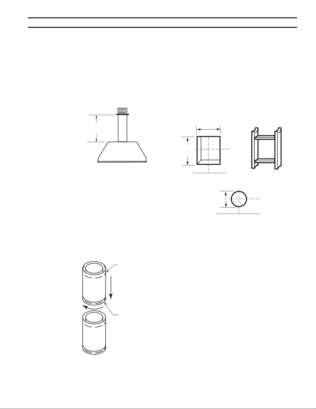
Install restrictor disc as shown in Figure 29 for vertically
vented applications.
Up to three (3) restrictor discs may be needed for 40'
installation.
The two (2) restrictor discs suppled will work for most instal-
lations. If a third disc is needed order Part No. 56D3027.
You may use a reducer to 4" x 6B\," or 4" x 7" in vertically
vented applications.
Restrictor
Disc
Fireplace Collar
FP2414
Figure 29 -
Install Restrictor Disc into Fireplace Collar
This Gas Fireplace has been approved for,
• Vertical installations up to 40' (12m) in height. Up to
a 10' (3m) horizontal vent run can be installed within
the vent system using a maximum of two 90° elbows.
Figure 30
• Up to two 45° elbows may be used within the horizontal
run. For each 45° elbow used on the horizontal plane,
the maximum horizontal length must be reduced by 18"
(450 mm).
Maximum horizontal length
No elbows = 10’ (3 m)
1x45° elbows = 8.5’ (2.6 m)
2x45° elbows = 7’ (2.1 m)
• A minimum of an 8' (2.5 m) vertical rise is required.
• Two sets of 45°elbows offsets may be used within the
vertical sections. From 0 to a maximum of 8' (2.5 m) of
vent pipe can be used between elbows. Figure 31
• Determine the roof pitch and use the appropriate starter
kit for offset installation.
10' Maximum
40'
Maximum
Height
8'
Minimum
Height
Support
Straps
Every 5'
Vertical
Support Straps Every 3'
10' Maximum
40'
Maximum
Height
8'
Minimum
Height
Support Straps Every 3'
FP1183
Figure 30 -
Support Straps for Horizontal Runs
• The maximum angular variation allowed in the system
is 270°. Figure 31
• The minimum height of the vent above the highest point
of penetration through the roof is 2' (610 mm).
23
75D2525
DVM Series Direct Vent Gas Fireplace
1. Determine the route your vertical venting will take. If
ceiling joist, roof rafters or other framing will obstruct
the venting system, consider an offset. Refer to
Figure 32 to avoid cutting load bearing members.
Pay special attention to these installation instructions
for required clearances (air space) to combustibles when
passing through ceilings, walls, roofs, enclosures, attic
rafters, etc. Do not pack air spaces with insulation. Also
note maximum vertical rise of the venting system and any
maximum horizontal offset limitations. Offsets must fall
within the parameters shown on Page 13, Figure 15.
2. Set replace in desired location. Drop a line plumb down
from the ceiling to the position of the ue exit. Mark the
center point where the vent will penetrate the ceiling.
Drill a small locating hole a this point.
Drop a plumb line from the inside of the roof to the ceiling
locating hole in the ceiling. Mark the center point where
the vent will penetrate the roof. Drill a small locating hole
at this point.
1
2
3
4
1
2
3
4
Example: Elbow 1 = 90°
Elbow 2 = 45°
Elbow 3 = 45°
Elbow 4 = 90°
Total Angular = 270°
Variation
FP1179
Figure 31 -
Maximum Elbow Usage
Figure 32 -
Offset with Wall Strap and 45° Elbows
Roof Flashing
Wall Strap
45° Elbows
Ceiling Firstop
FP1669
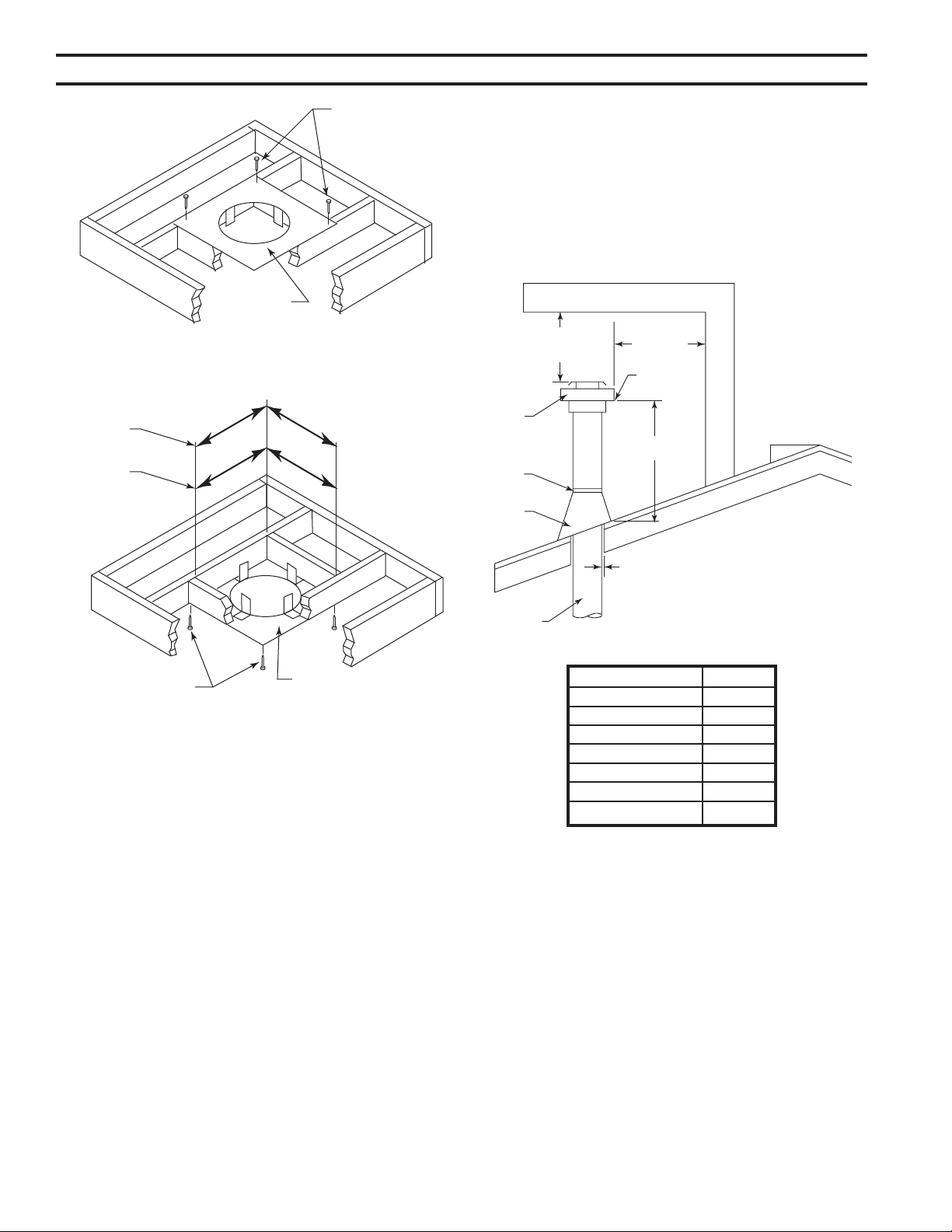
1. Cut a 10Z\x" (267 mm) square hole in the ceiling using
the locating hole as a center point The opening should
be framed to 10Z\x" x 10Z\x" (267 x 267 mm) inside dimen-
sions as shown in Figure 34 using framing lumber the
same size as the ceiling joist. If the area above the
ceiling is an insulated ceiling or a room, nail restop
from the top side. This prevents loose insulation from
falling into the required clearance space. Figure 33.
Otherwise, install restop below the framed hole. The
restop should be installed with no less than three nails
per side. Figure 34
2. Assemble the desired lengths of pipe and elbows nec-
essary to reach from the burner system ue up through
the restop. Be sure pipe and elbow connections are
fully twist-locked. Page 16, Figure 15
3. Cut a hole in the roof using the locating hole as a center
point. (Cover any exposed open vent pipes before
cutting hole in roof). The 10Z\x" x 10Z\x" (267 x 267mm)
hole must be measured on the horizontal. Actual length
may be larger depending on the pitch of the roof. There
must be a 1" minimum clearance from the vent pipe to
combustible materials. (Insulation should be considered
a combustible material) Frame the opening as shown
on Page 16, Figure 16.
4. Connect a section of pipe and extend up through the
hole.
24
75D2525
DVM Series Direct Vent Gas Fireplace
Figure 33 -
If area above is a room, install restop above framed
hole as shown
Firestop
Nails
FP1969
If an offset is needed to avoid obstructions, you
must support the vent pipe every three (3) feet. Use wall
straps for this purpose. Page 23, Figure 32. Whenever
possible, use 45° elbows instead of 90° elbows. The 45°
elbow offers less restriction to the ow of the ue gases
and intake air.
5. Place the ashing over the pipe section(s) extending
through the roof. Secure the base of the ashing to
the roof and framing with roong nails. Be sure roong
material overlaps the top edge of the ashing. There
must be a 1" clearance from the vent pipe to combustible
materials.
6. Continue to add pipe sections until the height of the
vent cap meets the minimum requirements as shown
in Figure 35.
You must increase vent height for steep roof
pitches. Nearby trees, adjoining roof lines, steep pitched
roofs, and other similar factors may cause poor draft or
down-drafting in high winds. Increasing the vent height
may solve this problem.
NOTE: If the vent pipe passes through any occupied areas
above the rst oor, including storage spaces and closets,
you must enclose pipe. You may frame and sheetrock the
enclosure with standard construction material. Make sure
to meet the minimum allowable clearances to combustibles.
Do not ll any of the required clearance spaces with
insulation.
2 ft.
Min.
2 ft. Min.
X
12
H*
Termination
Vent
Storm
Collar
Flashing
Lowest
Discharge
Opening
Concentric
Vent Pipe
1” Minimum Clearance to
Combustibles
FP1971
Horizontal Overhang
Figure 35 -
Minimum Chimney Clearance
Flat to 6/12 1.0
Over 6/12 to 7/12 1.25
Over 7/12 to 8/12 1.5
Over 8/12 to 9/12 2.0
Over 9/12 to 10/12 2.5
Over 10/12 to 11/12 3.25
Over 11/12 to 12/12 4.0
*H - Minimum height from roof to
lowest discharge opening of vent
Figure 34 -
If area above is not a room, install restop below
framed hole as shown
Nails
Firestop
1056O”
1056O”
956O”
956O”
FP1970
4 x 6B\,
Venting
5 x 8
Venting
25
75D2525
DVM Series Direct Vent Gas Fireplace
1. Flexible UL1777 listed venting may be used in any
venting application where rigid direct vent components
can be used.
Flex kits may not be modied. Flex
kits may be added to the end of a vent run made of rigid
vent sections using pipe manufacturer's approved ex
to pipe adapters. This may occur only if doing so does
not violate any of the venting length, height, routing,
horizontal to vertical ratio requirements or clearance
considerations detailed in this manual.
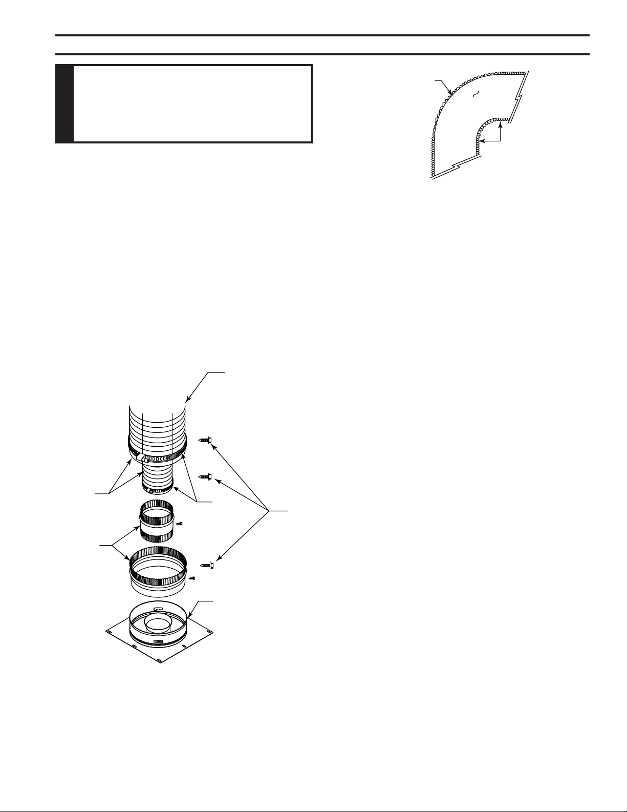
2. The ex adapter starter kit (DVFF8A/8) is used to attach
ex venting to the appliance starting collar. It includes
5" inner and 8" outer adapter rings. Figure 36
UL1777
Flex Vent
Screws
(3 places,
equidistant
just above
gear clamp)
1C\v" Flex-
ible Pipe
and Adapter
Outer
DVFF8A/8
Inner Adapter
Outer Adapter
Appliance
Starting
Collar
Figure 36 -
Typical Appliance Connection
UL1777
Flex Vent
5°
Radius
Figure 37 -
Minimum Radius for Flex Vent Section
FP1973
• The inner and outer adapter rings are required to
start all ex runs.
• Never install damaged or torn exible venting.
• Over tightening clamps may rip, tear, or otherwise
damage exible venting.
• The adapter kit does not include individual pipe sec-
tions which may be purchased separately. (UL1777
listed type venting only.)
3. Start the exible vent as follows:
A. Installing the inner ex adapter and pipe. Figure
38
1. Insert the long side of the 5" inner ring into
exhaust pipe, gently tap to seat into place, and
secure with screws.
2. Slide the small gear clamp over the inner exible
vent pipe, and push out of the way.
3. Pull and extend the inner exible vent.
4. Slide the inner vent onto the adapter collar, for a
minimum 1C\v" overlap.
5. Locate the clamp at approximately 3/4" from the
ex end and tighten.
6. Secure the clamped inner section with three self-
tapping screws, drilled equidistant, just above the
clamp perimeter.
B. Installing the outer ex pipe. Figure 36
1. Firmly insert the 8" outer adapter ring into the
outer appliance starting collar and secure with
screws.
2. Slide the large gear clamp over the outer exible
vent pipe, and push out of the way.
3. Pull and extend the outer exible vent.
4. Slide the outer vent onto the appliance collar outer
adapter for a minimum 1C\v" overlap.
5. Locate the clamp at approximately 3/4" from the
ex end and tighten.
6. Secure the clamped outer section with three self-
tapping screws, drilled equidistant, just above the
clamp perimeter.
C. Routing UL1777 ex pipe.
1. Always maintain the required clearance when
routing the ex vent assembly.
26
75D2525
DVM Series Direct Vent Gas Fireplace
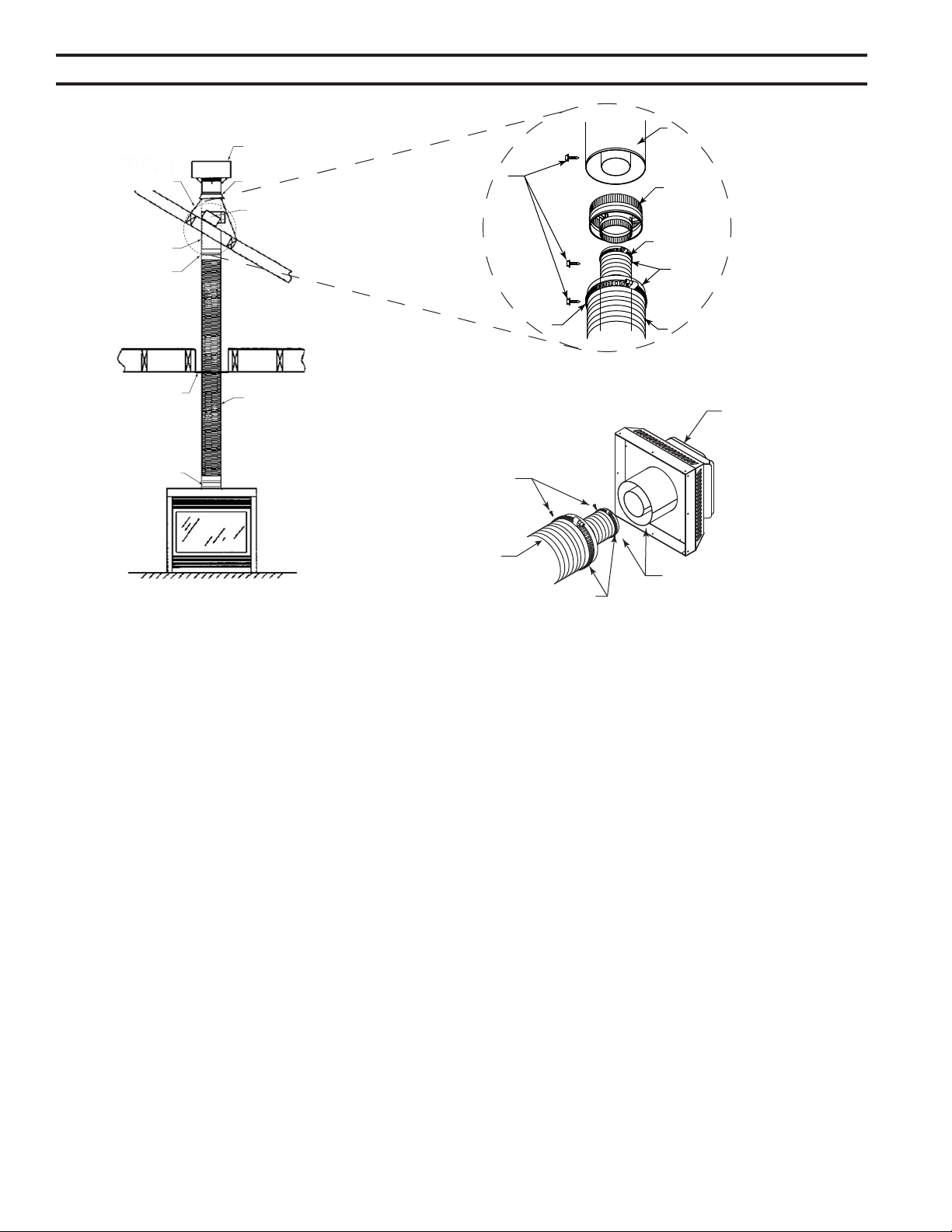
Termination
Cap
Storm Collar
Roof Sup-
port
Flashing
Rigid Pipe
Length
Flex to Pipe
Adapter
Firestop
UL1777 Flex
PIpe
Figure 38 -
Typical Vertical Flex Vent Installation
Screws
(3 Places
equidistant
just above
gear clamp)
Rigid Pipe Length
Flex to Pipe Adapter
Gear Clamp
1C\v" Flexible Pipe and
Adapter Outer Collar Over-
lap
UL1777 Flex Vent
Figure 39 -
Typical Pipe Connection
Gear Clamp
Screws
(3 Places equidistant
just above gear clamp)
Gear Clamp
UL1777 Flex Vent
1C\v" Flexible Pipe
and Collar Overlap
MHSC Horizontal
Vent Termination
Figure 40 -
Typical Horizontal Flex Vent Installation
DVFF8A/8 5" x 8"
to 5" x 8" Adapter
FP1974
2. Install restop spacers, Figure 38, when penetrat-
ing ceiling, attic spaces, or walls.
3. Do not allow the exible vent to bend in radius
tighter than 5" (127 mm). Figure 37
4. Horizontal runs of exible vent shall be supported
at maximum 2 foot intervals; vertical runs, ve feet
intervals. Metal strapping, properly secured, is an
acceptable means to support the exible vent.
5. Flexible vent spacers are to be installed at inter-
vals prescribed by the exible vent manufacturer;
and in such a way as to maintain concentric inner
and outer vent spacing.
D. Attaching exible venting to vertical termination
assemblies.
1. When using 5 x 8 ex pipe, an MHSC ex-to-pipe
adapter and/or rigid pipe section(s) is required to
connect the exible vent assembly to the verti-
cal termination by using three self-penetrating
screws.
2. Review Figure 39 and corresponding instruc-
tions for proper overlap, clamp and screw place-
ment.
3. Three each self-penetrating screws are drilled
opposite one another and below the gear
clamp.
4. Use only listed and approved terminations and
accessories, installed per the installation instruc-
tions and Figure 38.
E. Installing exible venting to horizontal termination
assemblies.
1. Connect the 5" exible vent to the horizontal
termination as in Figure 40.
2. Connect the 8" exible vent to the termination
ring as in Figure 40.
3. Review Figure 40 for proper overlap and clamp
placement.
4. Three each self-penetrating screws are drilled
opposite one another and below the gear lamp.
5. Use only listed an approved terminations and
accessories, installed per the termination instruc-
tions and Figure 40.
27
75D2525
DVM Series Direct Vent Gas Fireplace
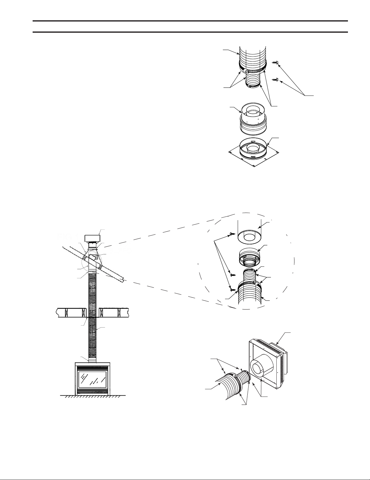
If you prefer to use 4" x 7" ex pipe, you must install model
7TDVP58 reducer (5" x 8" to 4" x 7") onto the replace
collar. Then follow the the assembly guidelines for 5" x 8"
ex venting.
Termination
Cap
Storm Collar
Roof Support
Flashing
Rigid Pipe
Length
Flex to Pipe
Adapter
(DVFFA/8)
Firestop
UL1777 Flex
PIpe
Figure 42 -
Typical Vertical Flex Vent Installation
Screws
(3 Places
equidistant
just above
gear clamp)
4" x 7" Rigid Pipe
Length
Flex to Pipe Adapter
(DVFFA/8)
Gear Clamp
1C\v" Flexible Pipe and Adapter
Outer Collar Overlap
UL1777 Flex Vent
Figure 43 -
Typical Pipe Connection
Gear
Clamp
Screws
(3 Places equidistant just
above gear clamp)
Gear Clamp
UL1777 Flex Vent
1C\v" Flexible Pipe and
Collar Overlap
MHSC Horizontal
Vent Termination
Figure 44 -
Typical Horizontal Flex Vent Installation
7TDVP58 5" x 8" to
4" x 7" Reducer
FP1974
UL1777
Flex Vent
Screws
(3 places,
equidistant just
above gear
clamp)
1C\v" Flex-
ible Pipe and
Adapter Outer
Appliance
Starting Collar
Figure 41 -
Typical 4" x 7" Appliance
Connection
5" x 8" to 4" x 7"
Adapter (7TDVP58)
Gear Clamp
FP1972a
28
75D2525
DVM Series Direct Vent Gas Fireplace
Use proper gas type for the replace you are installing. If you have conicting gas type, do not install
replace. See dealer where you purchased the replace for proper replace according to your gas
type.
When using copper or ex connectors use only ttings
approved for gas connections. The gas control inlet is
3/8" NPT.
Before installing replace and burner system, make sure you have the items listed below.
• External regulator • Piping (check local codes) • Sealant (resistant to propane/LP gas)
(supplied by installer) • Test gauge connection* • Sediment trap (recommended)
• Equipment shutoff valve* • Tee joint • Pipe wrench
• approved exible gas line with gas connector (if allowed by local codes — not provided)
* A CSA design-certied equipment shutoff valve with 1/8" NPT tap is an acceptable alternative to test gauge
connection. Purchase the CSA design-certied equipment shutoff valve from your dealer.
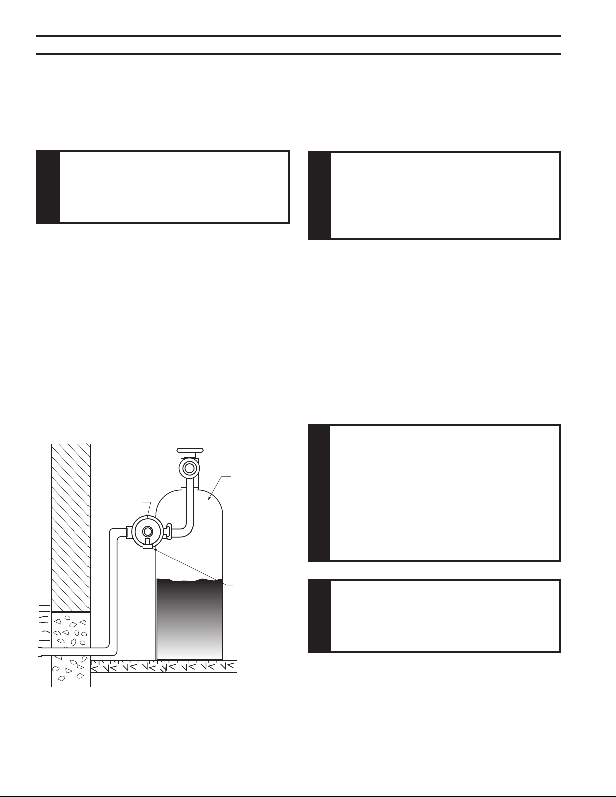
For propane/LP connections only, the installer must supply an external regulator. The external regulator will reduce
incoming gas pressure. You must reduce incoming gas pressure to between 11 and 13 inches of water. If you do not
reduce incoming gas pressure, burner system regulator damage could occur. Install external regulator with the vent
pointing down as shown in Figure 45. Pointing the vent down protects it from freezing rain or sleet.
External
Regulator
100 gal. (min)
Propane/LP
Supply Tank
Vent Pointing
Down
Figure 45 -
External Regulator with Vent Pointing Down
(Propane/LP Only)
FP1977
29
75D2525
DVM Series Direct Vent Gas Fireplace
The gas line connection may be made using 1/2" rigid tubing or an approved ex connector.
Since some municipalities have additional local codes it is always best to consult your local authorities
and the current edition of the National Fuel Gas Code ANSI.Z223.1, NFPA54. In Canada CSA-B149 (1
or 2) Installation Code.
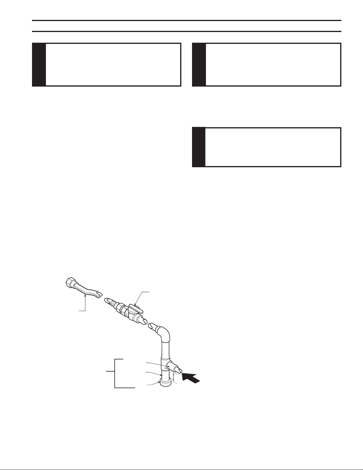
A listed manual shutoff valve must be installed upstream of
the appliance. Union tee and plugged 1/8" NPT pressure
tapping point should be installed upstream of the appliance.
Figure 46
Install main gas valve (equipment shutoff valve)
in an accessible location. The main gas valve is for turning on
or shutting off the gas to the replace.
Check your building codes for any special requirements for locating equipment shutoff valve to re-
places.
Apply pipe joint sealant lightly to male threads. This will prevent excess sealant from going into pipe.
Excess sealant in pipe could result in clogged burner system valves.
We recommend that you install a sediment trap/drip leg in supply line as shown in Figure 46. Locate
sediment trap/drip leg where it is within reach for cleaning. Install in piping system between fuel supply
and burner system. Locate sediment trap/drip leg where trapped matter is not likely to freeze. A sediment
trap traps moisture and contaminants. This keeps them from going into the burner system gas controls.
If sediment trap/drip leg is not installed or is installed wrong, burner system may not run properly.
Figure 46
3" Minimum
Pipe Nipple
Cap
Figure 46 -
Gas Connection
Tee Joint
Approved Flexible
Gas Line
CSA Design-Certied Equipment Shutoff Valve
with 1/8" NPT Tap*
Sediment Trap/Drip Leg
From Gas Meter
(4.0" w.c. to 10.5" w.c. Pressure)
From External Regulator
(11" w.c. to 13" w.c. Pressure)
30
75D2525
DVM Series Direct Vent Gas Fireplace
1. Check gas type. The gas supply must be the same as
stated on the appliance’s rating decal. If the gas supply
is different from the replace, Do not install the
appliance. Contact your dealer immediately.
2. To ease installation, a 18" (457 mm) ex line with manual
shut-off valve has been provided with on this appli-
ance. Install and attach 1/2" gas line onto shut-off
valve.
3. After completing gas line connection, purge air from
gas line and test all gas joints from the gas meter
to the replace for leaks. Use a solution of 50/40
water and soap or a gas sniffer.
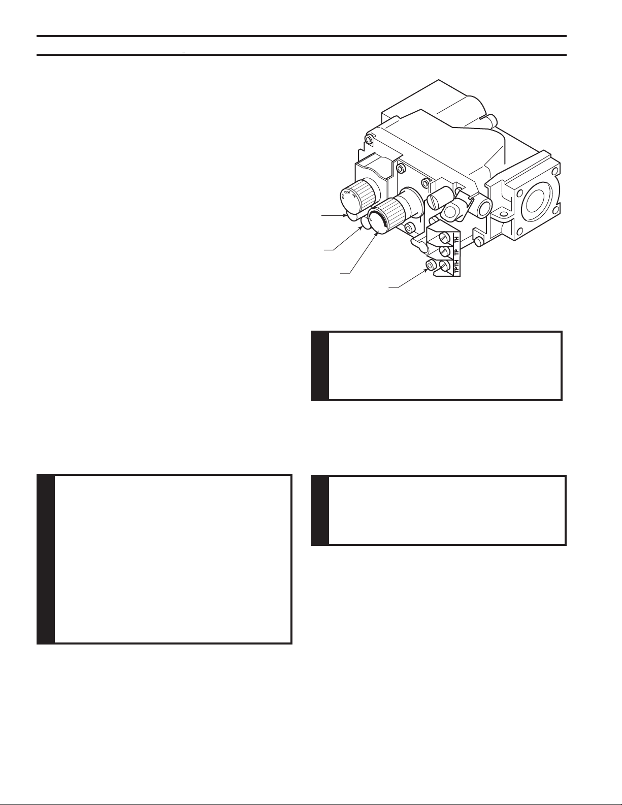
4. To adjust ame height, turn HI/LO knob to HI to get
maximum pressure to burner. Turn HI/LO knob to
LO to get minimum pressure.
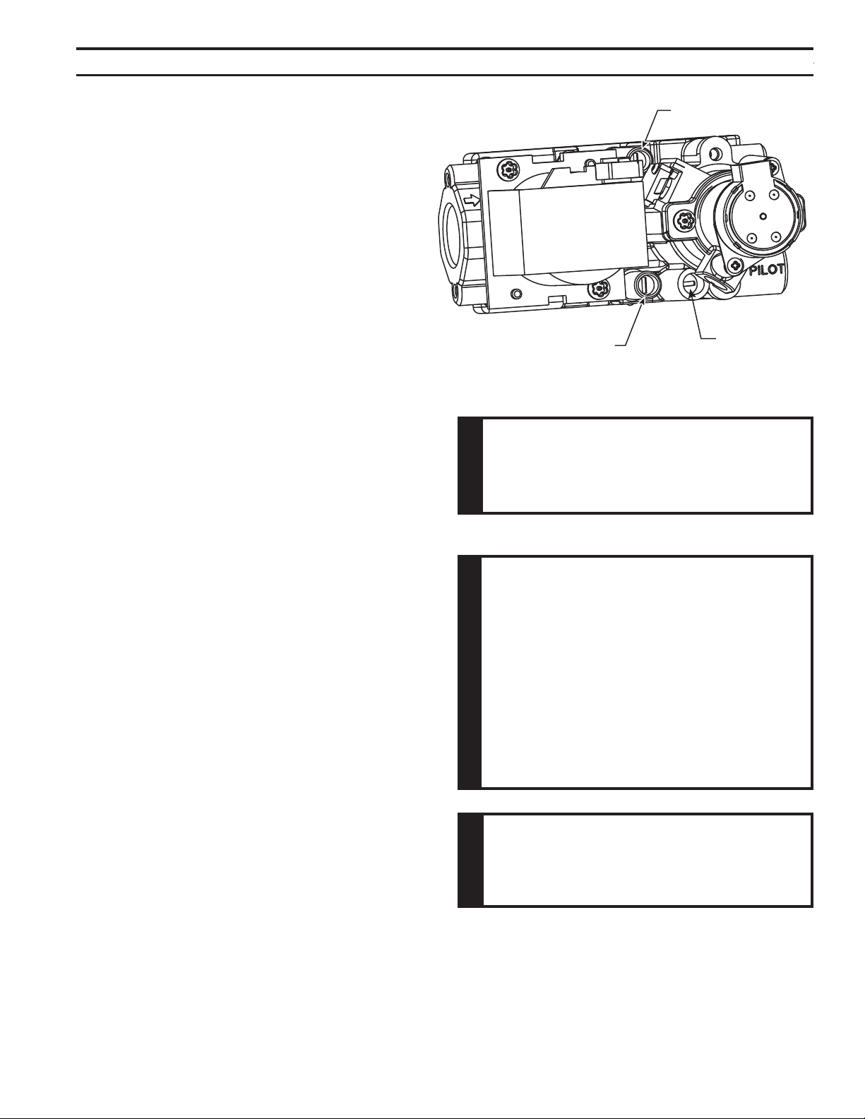
5. To check gas pressures at valve, turn captured
screw counter clockwise 2 or 3 turns and then place
tubing to pressure gauge over test point. Turn unit
to high. Figure 47. After taking pressure reading,
be sure and turn captured screw clockwise rmly
to reseal. Do not over torque. Check test points for
gas leaks.
This replace will work without any electrical supply except to operate blower and electronic igni-
tion system.
If installed in mobile home, replace must be bolted securely to oor.
FP1979
Figure 47 -
Gas Pressure Check at Gas Valve
Pressure
Test “IN”
Pressure
Test “OUT”
HI/LO Knob
Pilot Adjustment Screw
Verify proper operation after servicing.
31
75D2525
DVM Series Direct Vent Gas Fireplace
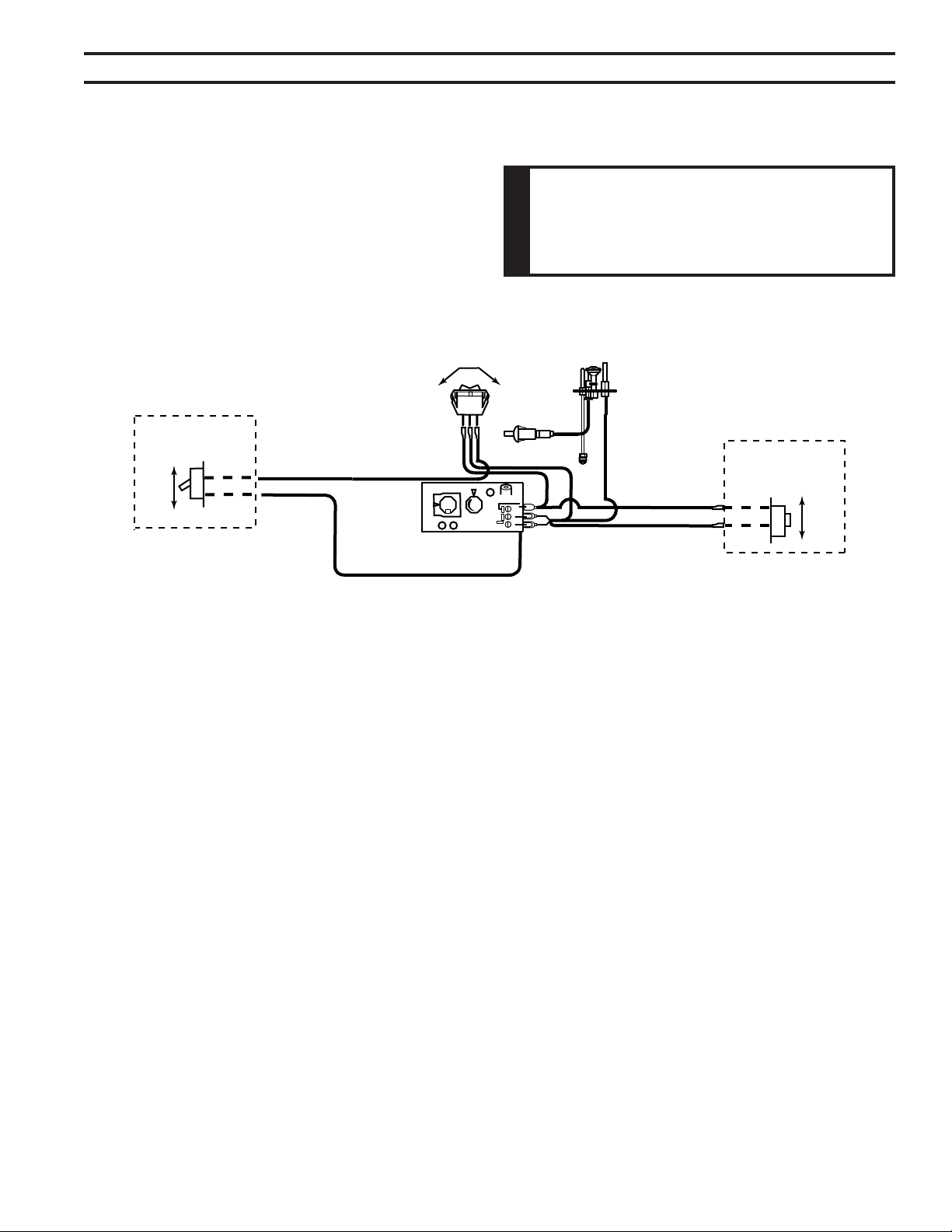
A remote wall switch and up to fteen (15) feet of 18 Ga.
wire may be used with this appliance. Attach the wall
switch in a junction box at the desired location on the
wall. Figure 48. Do not extend beyond the wall switch wire
length provided.
ON
OFF
OPTIONAL REMOTE
RECEIVER
ON
OFF
RS
PILOT
HI
LO
ON
OFF
TH
TP
TH/TP
ON
OFF
OPTIONAL WALL
SWITCH
GRAY
BLUE
BLACK
BLACK
BLACK
BLUE
WHITE
RS
Figure 48 -
Wiring Diagram for Wall Switch
(Millivolt Units Only)
32
75D2525
DVM Series Direct Vent Gas Fireplace
This appliance is equipped with a pilot which must be lit with built-in ignitor while following
these instructions exactly.
BEFORE OPERATING smell all around the appliance area for gas. Be sure to smell next
to the oor because some gas is heavier than air and will settle on the oor.
• Turn off all gas to the appliance.
• Open windows.
• Do not attempt to light any appliance.
• Do not touch any electric switch; do not use any phone in your building.
• Immediately call your gas supplier from a neighbor's phone. Follow the gas supplier's
instructions.
• If you cannot reach your gas supplier, call the re department.
Use only your hand to push in, or turn the gas control knob. Never use tools. If the knob will
not push in or turn by hand, don't try to repair it. Call a qualied service technician. Force
or attempted repair may result in a re or explosion.
Do not use this appliance if any part of it has been under water. Immediately call a qualied
service technician to inspect the appliance and to replace any part of the control system
and any gas control that has been under water.
Purge air from the supply line as follows:
• Open main shutoff valve.
• Unscrew main pressure test point.
• Leave inlet test screw open until gas comes in.
• When gas is owing, tighten inlet screw immediately.
1. Follow the pipe from the gas supply line connection to the gas valve. Check connection for
leaks with soap and water mixture.
2. Next check for gas leaks at the burner with soap and water mixture.
3. Check the pilot for gas leaks with soap and water mixture.
33
75D2525
DVM Series Direct Vent Gas Fireplace
You may check for gas leaks with the following
methods only:
• Soap and water solution
• An approved leak testing spray
• Electronic sniffer
NOTE: Remove any excessive pipe
compound from the connections.
Excessive pipe compound can set off
electronic sniffers.
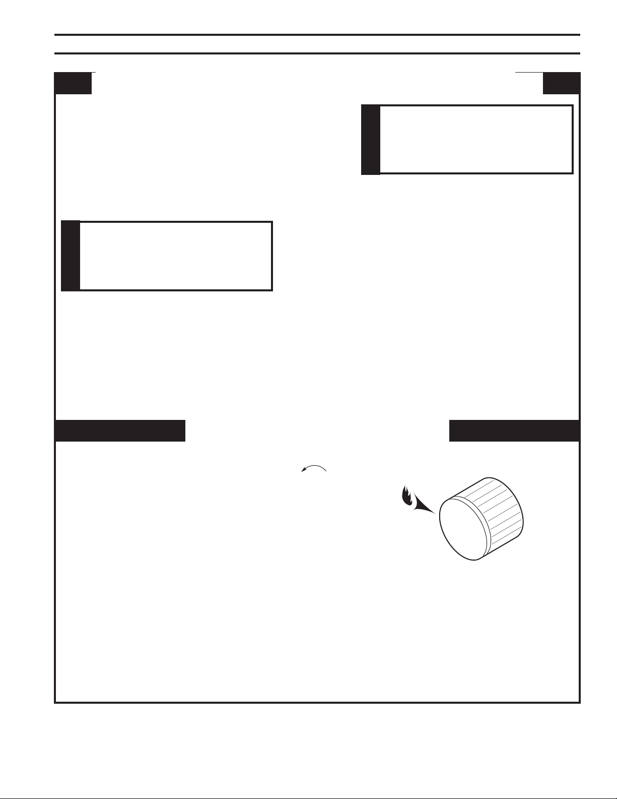
1. Depress and turn knob counterclockwise
to pilot position.
2. Depress fully and hold pilot gas knob. Depress piezo
ignitor as many times as needed to ignite the pilot.
Keep knob fully depressed for a few seconds.
Release and check that pilot continues to
burn.
If the pilot does not stay lit, repeat steps 1 and 2.
Pilot Position
Check for gas leaks in each of the following locations:
• Pipe from the gas supply line connection to the gas valve
• Burner connections • Field made joints / gas shutoff valve
• Pilot • Factory made joints
• Each joint or connection • All joints on valve and control body
PILOT
O
F
F
P
I
L
O
T
O
N
34
75D2525
DVM Series Direct Vent Gas Fireplace
O
F
F
P
I
L
O
T
O
N
PILOT
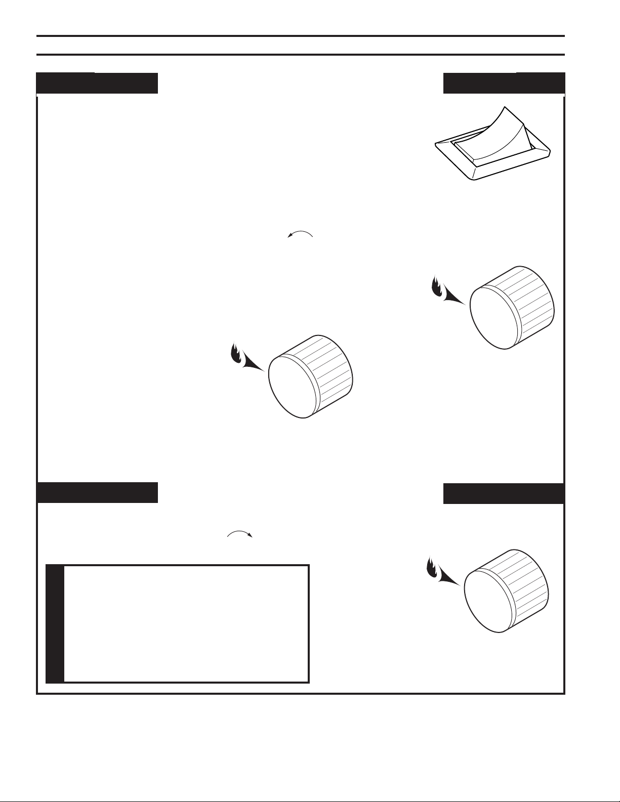
The “ON/OFF/RS” switch for the main burner can be found behind door
of the replace. This switch allows you to turn on and to turn off the main
burner without using the gas valve knob. Make sure the button is in the
“ON” position to light the main burner.
Depress and turn the knob counterclockwise to the “ON” position. It
will take less than four (4) seconds for the burner to ignite.
Depress and turn knob to pilot position to keep burner off while maintain-
ing the pilot light.
Depress and turn knob clockwise to “OFF” position.
Pilot Position
PILOT
O
F
F
P
I
L
O
T
O
N
PILOT
O
F
F
P
I
L
O
T
O
N
OFF
ON
RS
Off Position
On Position
On/Off/RS Switch
35
75D2525
DVM Series Direct Vent Gas Fireplace
1. Check gas type. The gas supply must be the same as
stated on the appliance’s rating decal. If the gas supply
is different from the replace, Do not install the
appliance. Contact your dealer immediately.
2. To ease installation, a 24" (610 mm) ex line with manual
shut-off valve has been provided with on this appliance.
Install and attach 1/2" gas line onto shut-off valve.
3. After completing gas line connection, purge air from
gas line and test all gas joints from the gas meter to the
replace for leaks. Use a solution of 50/50 water and
soap solution or a gas sniffer.
4. To check gas pressures at valve, turn captured screw
counter clockwise 2 or 3 turns and then place tubing
to pressure gauge over test point. Turn unit to high.
Figure 49. After taking pressure reading, be sure and
turn captured screw clockwise rmly to reseal. Do not
over torque. Check test points for gas leaks.
Figure 49 -
Signature Command Valve
Pressure Inlet
Pilot Adjustment
Screw
Pressure Outlet
FP1909a
1. This replace is equipped with the Signature Control
valve which operates on 6 volts. The 6 volt DC adapter
plugs into the replace junction box A/C power supply.
Four (4) “AA” batteries are used for back up during
power outages.
2. The Signature Command System can also be operated
without A/C power. The system can run on four (4) “AA”
batteries for approximately six (6) months under normal
use.
3. A/C power must be used to power the A/C module,
blowers, lights and AUX accessories if used with this
replace.
1. This replace may be used with a wall switch, wall
mounted thermostat and/or Signature Command wire-
less controls.
2. The command center control may be mounted on the
wall with the use of the SCSWEK 15ft. wall mount exten-
sion kit.
36
75D2525
DVM Series Direct Vent Gas Fireplace
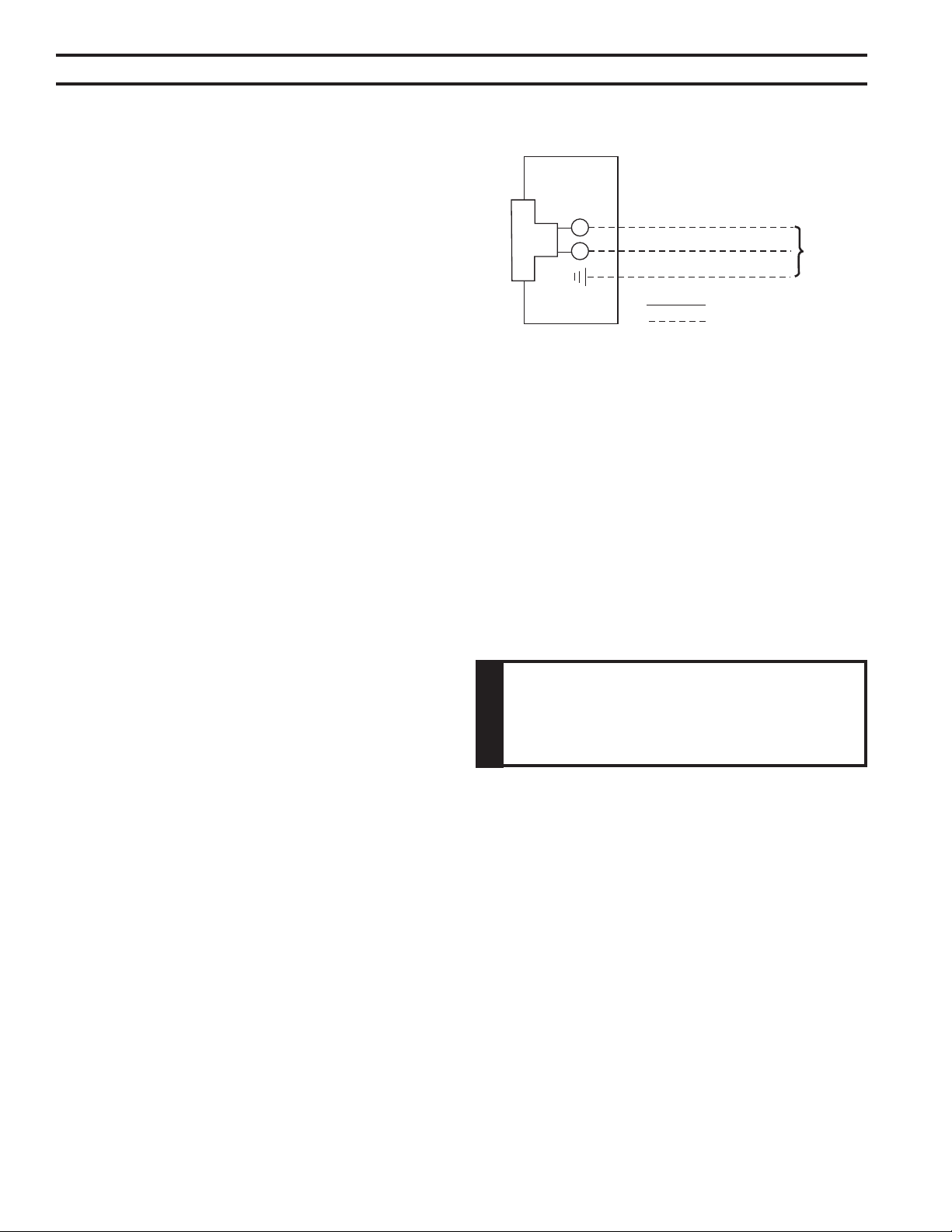
1. This should be done before framing the replace. Wire the receptacle into an electrical circuit.
Wire with minimum 60° C wire in accordance with prevailing
codes.
2. Remove the external junction box cover by removing the
screw from the side of the outside rebox wall. Junction box
was installed at the factory.
3. The junction box cover has a factory installed “romex” style
strain relief connector. After connecting the wires, route the
wire leads through this connector. Refer to the wiring dia-
gram in Figure 50.
Figure 50 -
Junction Box Wiring Diagram
Junction Box
Factory Supplied
Not Supplied
120V AC
60Hz
The command center may be mounted on the wall with
the use of the SCSWEK Kit (15ft. cable, junction box, wall
cover).
Mount the junction box provided at the desired location
on the wall. Do not extend beyond the 15 ft. wire cable
provided. If a longer distance is required, the 15 ft. may be
extended up to 30 ft. maximum by using two (2) SCSWEK
cables plugged together.
Route the wire from junction box to lower control area at
bottom of replace. Unplug the 12" cable from the com-
mand center. Attach the connector to the pins from wire
by pushing in to connector making sure to follow the color
code on connector. Plug the 15 ft. extension cable into the
2 ft. cable. Remove command center from the replace
and plug the other end of the extension cable into the
command center. Snap on wall cover provided and screw
to junction box.
The wall switch wire connection is located off the 2 ft. wire
harness from the control box to the command center. Fig-
ure 51. The connection is labeled “Wall Switch”. Unplug
the male and female connectors and connect the two (2)
low voltage wires provided. Run wire to desired location
on wall. Up to 50 ft. of 18 ga. wire may be used if neces-
sary. Attach wires to wall switch. Mount the wall switch in
to junction box and screw on cover.
37
75D2525
DVM Series Direct Vent Gas Fireplace
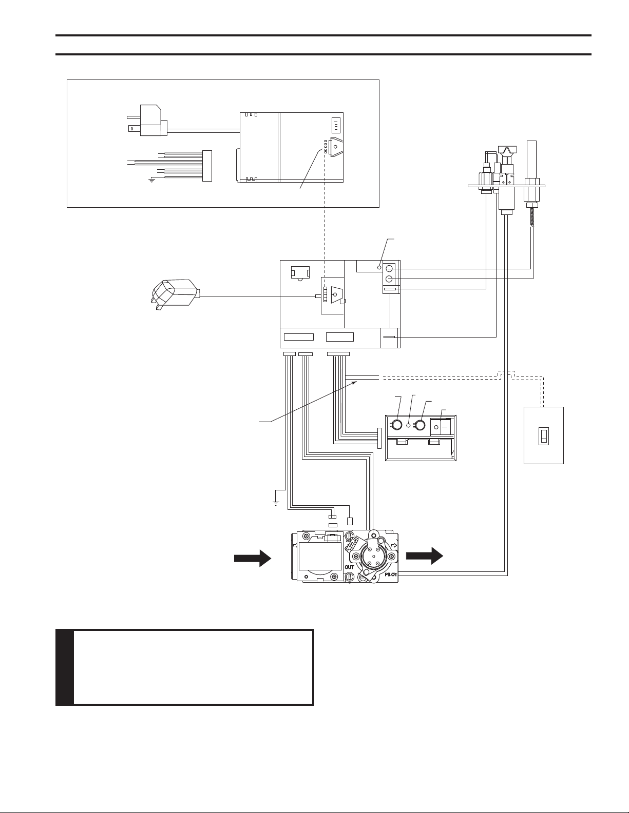
To Junction Box
in Fireplace
Optional
AC Module
{
White
Black
Optional
Light
White
Black
{
Optional
Blower
White
Black
{
Optional
Aux.
Green
Plug in
Connector
Connector Pin
To Control Board
Input 300 Watt Max. Each
Optional A/C Module Replaces 6V Adapter
When Used
6V AC
Adapter
Control Board
RF Receiver
ON/OFF Button
Pilot
Black / Thermopile
Red / Thermopile
Sensor
Ignitor / Sparker
Conversion
NG/LP
Plug-in Connector
Control Board to Command Center
OFF/LO
LED
ON/HI
Master Switch
Command Center
Optional
Wall Switch
Plug-in Connector
Stepper Motor to
Control Board
DC Power/Green
Ground
Plug-in Connector
Control Board to
Solenoid
Gas In
Gas Out
Pilot Gas Tubing
Valve
Figure 51 -
Signature Command Wiring Diagram
Wall switch wires must be con-
nected together if a wall switch is not
being used.
38
75D2525
DVM Series Direct Vent Gas Fireplace
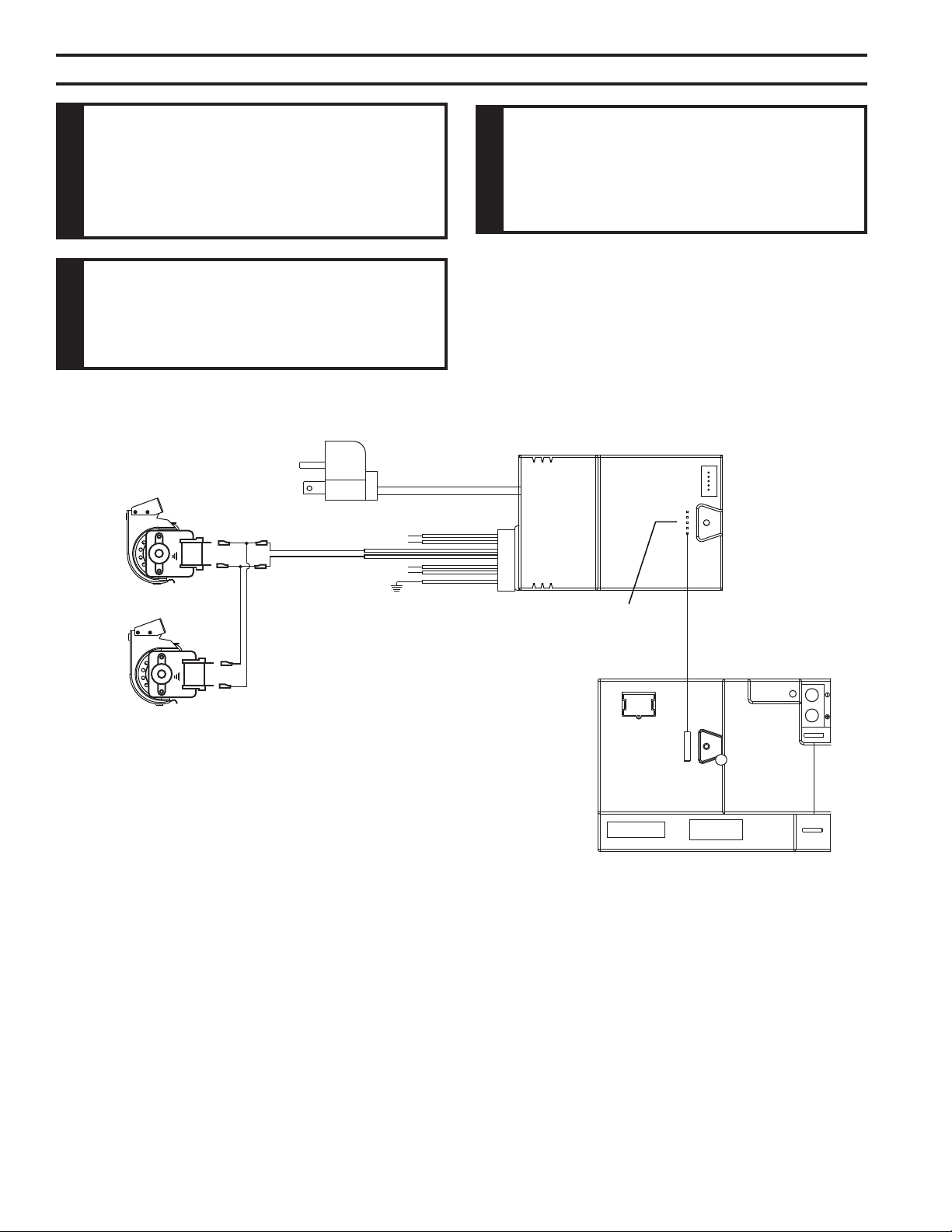
To Junction Box
In Fireplace
WHITE
BLACK
WHITE
BLACK
BLACK
WHITE
GREEN
Connector
Pin To Contro l Box
{
{
Optional
Light
Optional
AUX
Blower (300w Max)
Blower (300w Max)
Figure 52 -
BLOTSDVSC Blower Wiring Diagram
FP2103
The BLOTSDVSC Blower Kit requires the SCSACM A/C
Module and the TSFSC remote to install and operate this
kit. Refer to blower instructions for installation.
39
75D2525
DVM Series Direct Vent Gas Fireplace
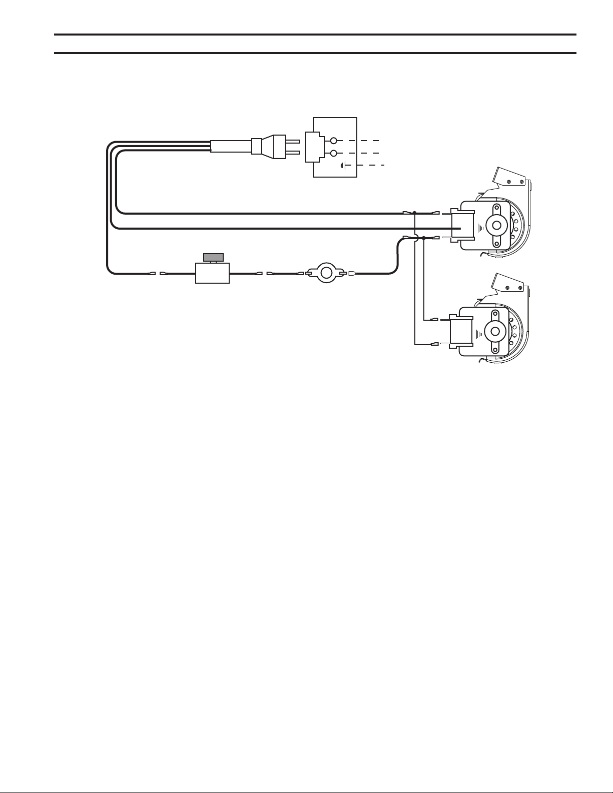
BLACKBLACKWHITE
GREEN
BLACK
BLACKWHITE
Receptacle
Junction
Box
120VAC
Speed Control
Figure 53 -
BLOTSDV Blower Wiring Diagram
FP2685
Before installing the blower, wire the receptacle into an
electrical circuit. This should be done before framing the
replace. Wire with minimum 60° C wire in accordance
with prevailing codes.
40
75D2525
DVM Series Direct Vent Gas Fireplace
This appliance is equipped with an ignition device which automatically lights the pilot. Refer
to the instructions for match lighting.
BEFORE OPERATING smell all around the appliance area for gas. Be sure to smell next to
the oor because some gas is heavier than air and will settle on the oor.
• Do not attempt to light any appliance.
• Do not touch any electric switch; do not use any phone in your building.
• Immediately call your gas supplier from a neighbor's phone. Follow the gas supplier's
instructions.
• If you cannot reach your gas supplier, call the re department.
Use only your nger to push in the master switch. Never use tools. If the switch will not func-
tion by hand, do not try to repair it. Call a qualied service technician. Force or attempted
repair may result in a re or explosion.
Do not use this appliance if any part of it has been under water. Immediately call a qualied
service technician to inspect the appliance and to replace any part of the control system and
any gas control that has been under water.
continued on next page
41
75D2525
DVM Series Direct Vent Gas Fireplace
1. Read the safety information above.
2. This appliance is equipped with an ignition device which automatically lights the burner. Do not try
to light the burner by hand.
3. With ve (5) minutes to clear out any gas. Then smell for gas, including near the oor. If you smell
gas, Follow "B" in the safety information on page 38. If you do not smell gas, go to next step.
4. Press the master switch to the "ON" (-) position. Within eight (8) seconds it will beep once. This
indicates the system is ready.
5. Press "ON " button. Sparker will spark and pilot ame will light.
6. Once pilot ame is established, the main burner ame will light automatically.
7. If the pilot will not stay lit after several tries, turn the master switch to "OFF" and call your service
technician or gas supplier.
1. Turn master switch to "OFF".
2. Turn off all electrical power to the appliance if service is to be performed.
ON
Master
Switch
OFF
42
75D2525
DVM Series Direct Vent Gas Fireplace
• Easy Access Function Operation and System Conguration
• Operation Conrmation/Fault Diagnostic Indications (LED/
Buzzer)
• ON/OFF/HI/Med/Low Operation
• Optional Wall Mounting
• Electronic Ignition
• Pilot Lockout safety feature
• Electric Power Regeneration from Thermopile to save battery
• 6-hour Automatic Shut Down Option
• Convenient NG/LP Gas Type Conversion
• Standing Pilot/Intermittent pilot Conversion
• Previous settings Restoration Ability (Memory Off)
• Uninterrupted Operation During Power Outage (Automatic
Battery Backup)
• ON/OFF RF Remote Receiver
• Optional Transmitter Learn Capability
• Easy Snap-on Design
• Embedded Compact 120 VAC Adapter with Auto Battery
Back up Feature
• Remote Controlled 3-step Blower, Lighting, and On/Off Auxiliary AC Outputs
TSFSC TSTSC TSMSC RTSC RMSC
Three Flame Height Settings X X X X X
Low battery Indication for Transmitter X X X X X
Child Proof Lock-out X X X X X
LCD Backlight X X X X X
Security Codes 16 X X X X X
Countdown 6 hr Timer X X X -- --
Standard Thermostatic Control Mode X X -- X --
Smart Mode
®
Thermostat (Auto Flame & Blower Modulation) X X -- -- --
Three Brightness Settings for Lights X -- -- -- --
Three Speed Control for Blower X -- -- -- --
On/Off Auxiliary X -- -- -- --
Programmable Timer to turn blower on and off X -- -- -- --
The Command Center uses four (4) "AA" batteries as back up for power outages. The system can operate for ap-
proximately six (6) months on battery power.
1. Press down the battery door tabs and pull out to remove battery door.
2. Install the batteries as indicated on Command Center.
3. Close battery door by snapping in place.
4. When the four (4) batteries are installed the system will operate without power.
5. The batteries should be replaced when the LED indicates low battery or at least once a year.
RF Receiver
ON/OFF
NG/LP
Conversion
To Thermopile
To Sensor
To Sparker
To Command Center
To Stepper Motor
To Valve
Battery Door
Master Switch
ON
LED
OFF
Figure 54 -
Signature Command System Components
6 V A/C
Adapter
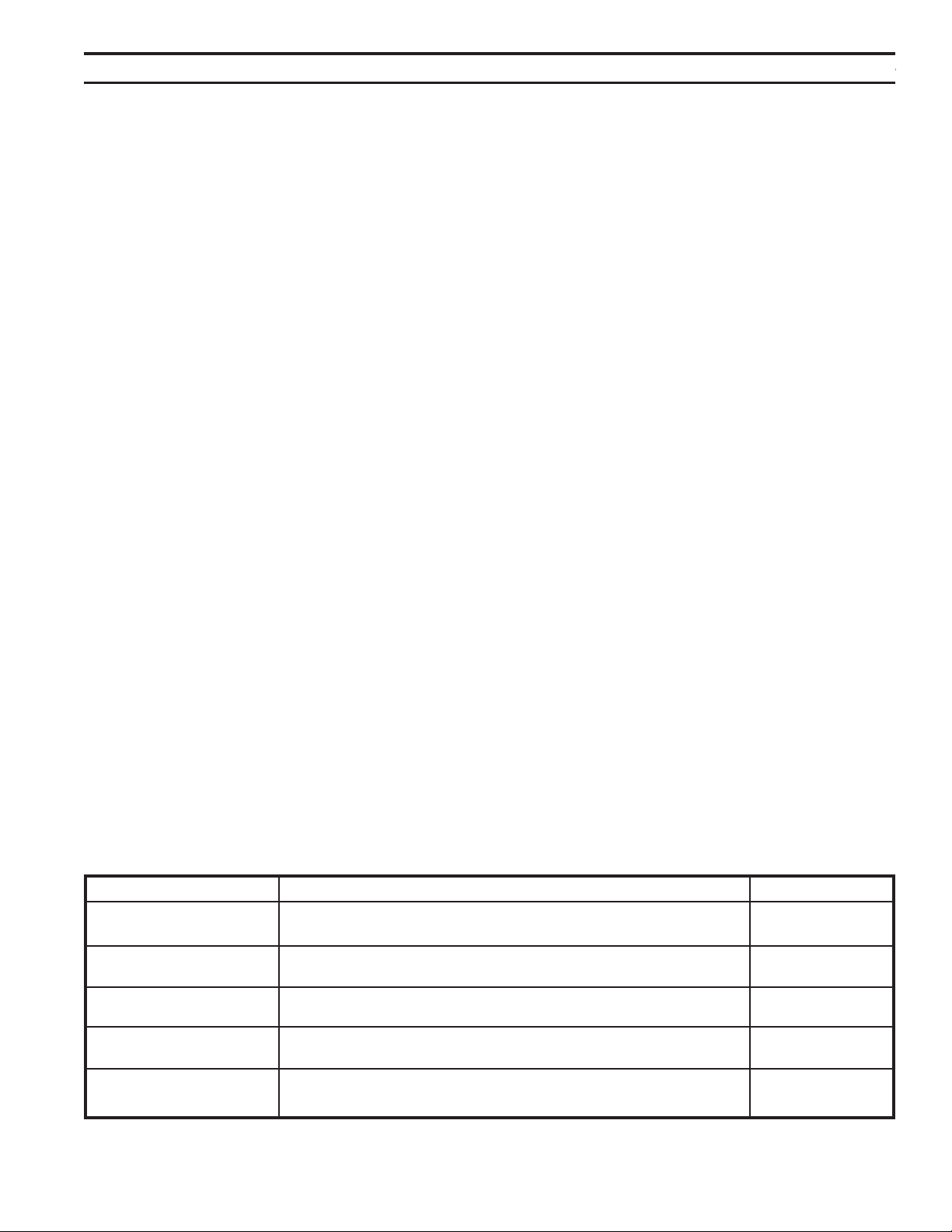
43
75D2525
DVM Series Direct Vent Gas Fireplace
Intermittent/Standing Hold the ON ▲ button while turning on the master switch Intermittent
Pilot Setup (Beep once for standing pilot, twice for intermittent pilot) Pilot
Standing Pilot Temp. Hold the ON ▲ button 3 seconds (when the master switch
Shutoff on the main burner is off)
RF Remote Receiver Push the RF receiver On/Off button on the control board RF OFF
On/Off Beep once for ON and beep twice for OFF
Learn Remote Hold the OFF ▼ button while turning on the master switch
Transmitter (Beep twice then press any handheld remote button)
6-hour safety Press the ON ▲ button and OFF ▼ button simultaneously ON
shutdown setup (Beep once for ON, twice for OFF)
All System conguration/setup is done on the Command Center.
When using On/Off wall switch, the switch must be in the ON position to perform all congura-
tion set ups at the command center.
1. Holding the ON button on the Command Center while turning on the master switch will toggle be-
tween standing pilot and intermittent pilot.
2. After the above operation, one beep (for standing pilot) or two beeps (for intermittent pilot) will be
given as conrmation.
1. The system comes preset from the factory with a six (6) hour shutdown from its last command of
operation. This is done to prevent the replace from continuing to operate if unattended. You may
disable this feature if you wish.
By disabling this feature, your replace may continue to operate unattended.
2. When the master switch is in the ON position (“-”), pressing the ON button and the OFF button on the
Command Center simultaneously will toggle between enabling and disabling the six-hour shutdown
option.
3. After the above operation, one beep (for enabling the six-hour shutdown option) or two beeps (for
disabling the six-hour shutdown option) will be given as conrmation.
1. The RF receiver button located on the Control Board must be in the on position before the learn
function can begin. Use paper clip to depress button. One beep for RF receiver ON or two beeps
for RF receiver OFF will be given as conrmation. Refer to Figure 57 for location.
2. After the RF receiver is on, holding the OFF button on the Command Center while turning on the
master switch will activate the learn function for the transmitter.
3. After the above operation, two beeps will be given and the green LED on the Command Center will
ash for 10 seconds.
4. During the 10 seconds, press the OFF button on a transmitter to learn. Another two beeps will be
given to conrm a successful learning. Refer to transmitter instructions for remote operations.
To shut off the standing pilot for service or summer shut down, press and hold the ON button on the
Command Center for 3 seconds when the master switch is in the ON position (“-”) and the main burner
is off.
: Pilot will resume the next time system is turned on.
When On/Off wall switch is used, it must be in the On position to perform all system setups.
44
75D2525
DVM Series Direct Vent Gas Fireplace
1. Turn on the master switch and wait for a beep.
2. Press the ON button on the Command Center or turn on wall switch. Pilot will light and burner will come on High set-
ting or last memory setting (See Turning Off Fireplace below). For memory feature.
1. If the pilot doesn’t light after sparking for 30 seconds, pilot trial lockout happens. The LED on the Command Center
ashes Green once every 2 seconds, until reset.
2. If the pilot ame is lost during normal operation, the system will try three (3) times to relight after three (3) failures,
ame loss lockout happens. The LED on the Command Center ashes Red-Green once every 2 seconds, until re-
set.
3. Turning the master switch on the Command Center to the off position, then ON again will reset the system.
1. Press the ON button (on the Command Center) once to turn on the main burner with maximum ame height.
2. Press the OFF button to decrease ame height. The rst two presses will decrease the ame height to medium and
low.
3. The third press on OFF will turn off the main burner. In standing pilot conguration, the pilot will stay; in intermittent
pilot conguration, the pilot will be shut off.
There are three ways to turn the replace off.
1. Flip the master switch to the off (“O”) position. (This will turn the entire system OFF.)
2. Press the OFF button to Medium, Low, then Off.
3. Hold the OFF button anytime for three seconds or by turning off the wall switch. These two commands of OFF are
(Memory Off) the system will remember all last settings before turning off. The next time the replace is turned on, all
settings will resume. To reset, change to the desired settings and shut off by using the Memory Off commands and
the system will be reset to those new settings.
The following functions are available on the Command Center.
The Command Center has a self-diagnostic LED enabling you to troubleshoot problems and potentially avoid a ser-
vice call. Please refer to the charts below for indicator reference.
Power Up Flip the master switch to the ON ("_") position to power up the system
Fireplace ON Press the ON ▲ button on the Command Center or turn on wall switch to turn the replace on
Fireplace OFF Flip the master switch to the OFF ("o") position OR press the OFF ▼ button 3
times OR for Memory Off, hold the OFF ▼ button 3 seconds, or turn off wall switch
Flame Height Up Press the ON ▲ button once to turn on the replace with maximum ame height
Flame Height Down Press the OFF ▼ button to lower the ame height to Medium and Low
Conversion Cover Missing One RED (1 time)
Spark Fail Two RED (1 time)
No Sensor Signal Three RED (1 time)
Pilot Lockout - trial One GREEN, every 2 sec. (until manual reset)
Pilot Lockout - ame loss One RED-GREEN, every 2 sec. (until manual reset)
Low Battery One RED, every 10s (continuously)
No or Low Thermopile Power Two RED, every 10s (continuously)
Learning GREEN Flashes, every 1 sec. (for 10 sec.)
AC Power On GREEN solid
Pressure Switch Failure One RED every 2 sec. (until manual reset)
Power Vent Only
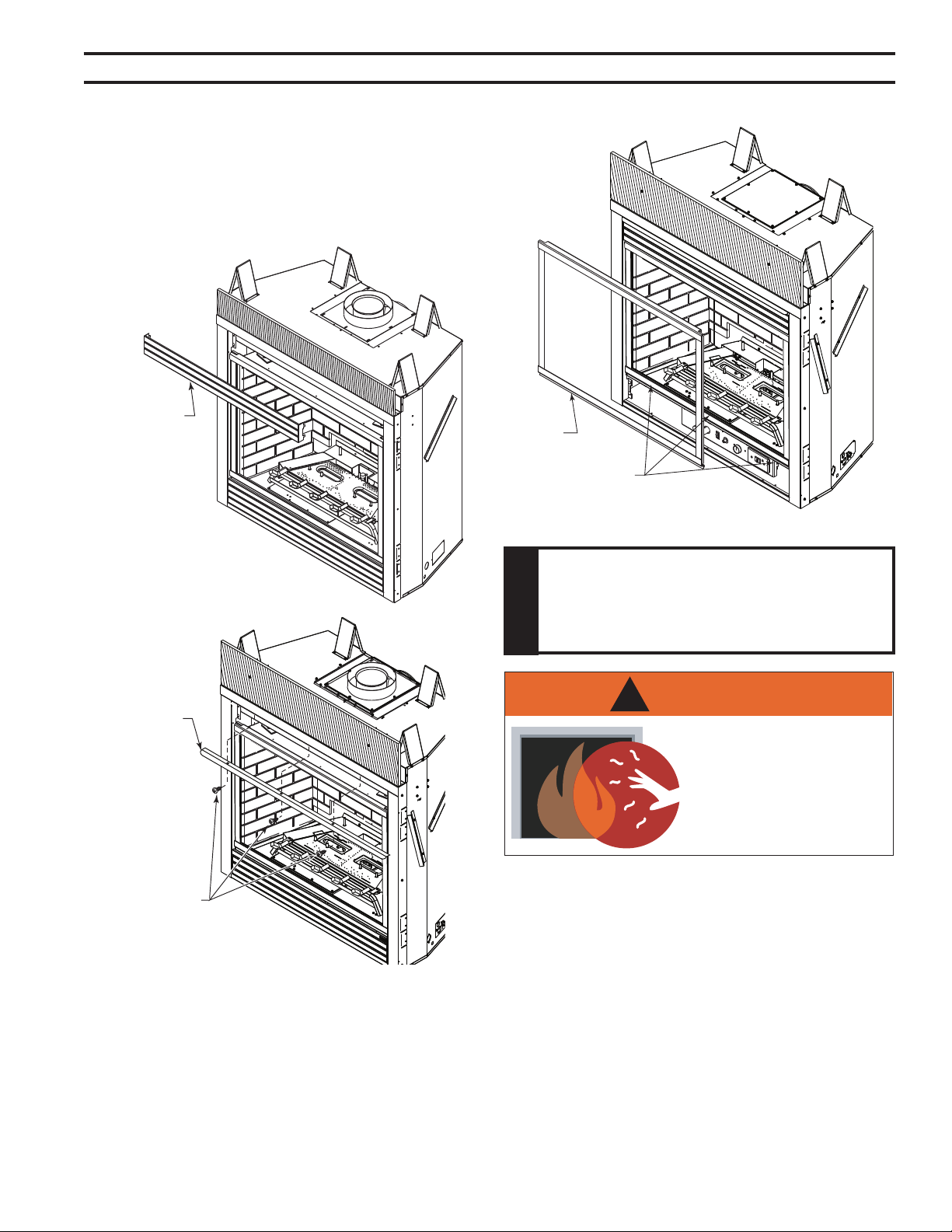
45
75D2525
DVM Series Direct Vent Gas Fireplace
Remove top louver assembly before installing eyebrow.
1. Unhook top louver assembly. Set aside. Figure 55
2. Attach canopy to underside of top outer shell with three
(3) screws provided. Figure 56
3. Hook top louver assembly back into place.
1. Remove louver assembly from the top.
2. Release three (3) clamps on bottom of replace. Figure
57
3. Tilt glass frame out and lift glass frame up until it clears
hook on top of replace.
4. Set glass frame aside.
Figure 55 -
Remove Top Louver Assembly
Louver
Assembly
FP2417
Figure 56 -
Install Canopy
Eyebrow
Screws
FP2418
Figure 57 -
Remove Glass Frame
Glass
Frame
Clamps
FP2419
WARNING
!
HOT GLASS WILL
CAUSE BURNS.
DO NOT TOUCH GLASS
UNTIL COOLED.
NEVER ALLOW CHILDREN
TO TOUCH GLASS.
1. Install oor brick before installing logs or rock wool.
2. Install the rear brick panel by sliding it over the existing
bracket fastened to the rear of the rebox.
3. Remove the existing screws fastened to the sides of the
rebox toward the tops.
4. Slide the right panel into place and secure the panel
using one of the brackets provided with the kit and one
of the screws removed earlier.
5. Repeat step 3 for the left panel.
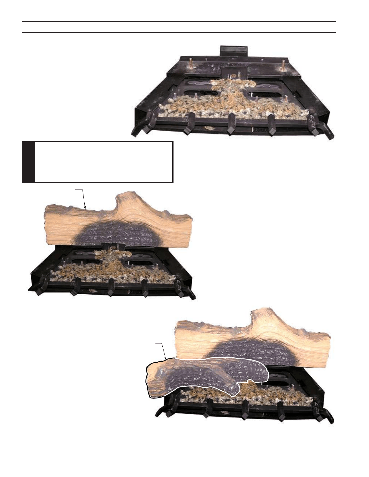
46
75D2525
DVM Series Direct Vent Gas Fireplace
Figure 58 -
Place Rock Wool
LG664
2. Place the rear log by aligning the holes in the
bottom of the rear log with the two pins located
at the rear of the burner on the bracket. Fig-
ure 59
LG665
Rear Log
Figure 59 -
Place Rear Log
Left Middle
Log
LG667
3. Place the left middle log by aligning the
holes in the bottom of the log with the
two pins located on the left side of the
burner. Figure 60
1. Distribute one layer of rock wool to cover
all round burner ports. Do not cover rect-
angular slots, located in front and rear.
Figure 58
Placing rock wool on burner provides
glowing embers. For best results, pull the
rock wool apart into pieces the size of a dime
or smaller.
Figure 60 -
Place Left Middle Log
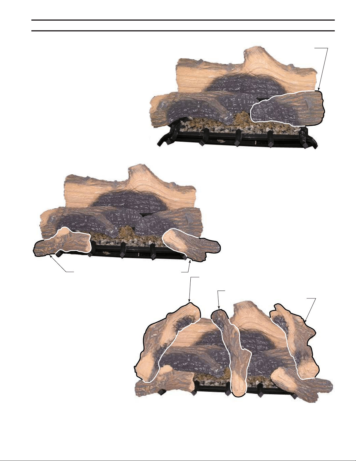
47
75D2525
DVM Series Direct Vent Gas Fireplace
Right Middle Log
Figure 61 -
Place Right Middle Log
LG668
4. Place the right middle log by aligning the holes in
the bottom of the log with the two pins located on
the right side of the burner. Figure 61
Left Front
Log
Right
Front Log
LG669
Figure 62 -
Place Left and Right Front Logs
5. Place the front left log by setting the notch
on the bottom of the log on the very far
left tong of the grate, and resting the right
end of the log onto the second left tong of
the grate. Figure 62
6. Place the front right log by setting the
notch on the bottom of the log on the very
far right tong of the grate and resting the
log on the leg of the grate. Figure 62
Upper Left Log
Upper Middle Log
Upper Right
Log
LG670
Figure 63 -
Place Upper Left, Right and Middle Logs
7. Place the upper left log by matching
the two protrusions on the rear and
left middle logs with the notches
on the bottom of the upper left log.
Figure 63
8. Place the upper middle log by match-
ing the protrusions located at the
middle of the rear log with the notch
on the bottom of the log. Rest the
front end of the log on the right side of
the middle tong of the grate. Figure
63
9. Place the upper right log by matching
the two protrusions on the rear and
right middle logs with the notches
on the bottom of the upper right log.
Figure 63
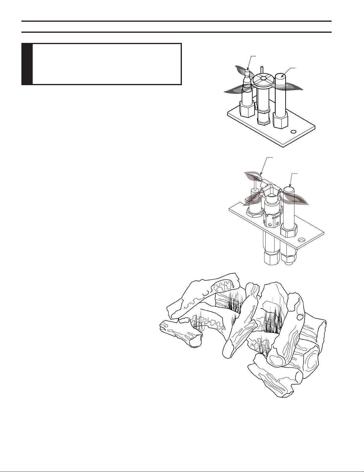
48
75D2525
DVM Series Direct Vent Gas Fireplace
Keep the control compartment, logs, and burner areas
surrounding the logs clean by vacuuming or brushing at
least twice a year. Make sure the burner porting, pilot air
opening and burner air opening are free of obstructions
at all times.
The ames from the pilot should be visually checked as
soon as the heater is installed and periodically during
normal operation.
Figure 64. The
pilot ame has three distinct ames, one engulng the
thermopile, one engulng the thermocouple or sensor, and
the other reaching to the main burner.
Inspect area around the injector. Remove any lint or foreign
material with a brush or vacuum.
Figure 65 -
Burner Flame Appearance
LG671
The ames from the burner should be visually
checked as soon as the heater is installed and
periodically during normal operation. In normal
operation, at full rate, and after operating for about
15 to 30 minutes, the ame should be yellow and
slightly taller than the rear log. Figure 65
If the ame is blue and only in the center, turn off unit
and let cool. After unit is cool, remove logs and check
to make sure rock wool is placed correctly. Replace logs.
The type of installation, vent system conguration, and
wind effects may cause the ame patterns to vary.
Thermopile
Thermocouple
Figure 64 -
Pilot Flame
FP1943
Thermopile
Sensor
FP2453

49
75D2525
DVM Series Direct Vent Gas Fireplace
The replace and venting system should be inspected before initial use and at least annually
by a qualied eld service person. Inspect the external vent cap on a regular basis to make
sure that no debris is interfering with the airow. Inspect entire venting system to ensure proper
function.
Thoroughly clean the inside of the glass door after using the replace for ten hours. Periodically
clean the glass door as necessary.
When cleaning the glass, remember:
• Allow glass to cool before removal.
• NEVER use abrasive materials.
• Keep children and pets a safe distance away.
• Never operate the replace without the glass door properly secured.
• Never operate the replace if the glass is broken.
• Replace any glass that is chipped, cracked, or broken. Replacement glass door assem-
blies MUST be supplied by the replace manufacturer –
• Handle glass door with care to avoid striking or scratching it on hard objects.
To clean glass door, follow “Glass Removal” procedure outlined in the Canopy Installation and
Glass Removal section. Film deposit on the inside of the glass should be cleaned off using a
nontoxic, non-corrosive, non-abrasive, mild cleaning solution. Simply apply an adequate amount
to the glass and wipe off with a damp cloth. After all maintenance has been completed, re-install
glass door.
Leave logs installed in the replace for cleaning. Vacuum surface of the logs with a brush attach-
ment. If logs must be removed for cleaning, handle carefully by holding gently at each end.
Gloves are recommended to prevent skin irritation from ceramic bers. If skin becomes irritated,
wash gently with soap and water. Vacuum surface of logs with brush attachment or brush logs
with a soft bristle brush (i.e. clean, dry paintbrush). To place logs back in the replace, see the
Log and Rock Wool Installation.
Replace or add rock wool as required following installation instructions in the Log and Rock
Wool Installation section of this manual.

50
75D2525
DVM Series Direct Vent Gas Fireplace
1. Spark ignitor will
not light pilot after
repeated triggering of
piezo.
2. Pilot will not stay lit
after carefully follow-
ing lighting instruc-
tions.
3. Pilot burning, valve
knob turned to “ON”,
switch is turned to
“ON” or “RS”, but
burner will not ignite.
A. Wire disconnected.
B. Defective ignitor.
C. No gas or low gas pres-
sure.
D. No Propane/LPG in tank
A. Defective thermocouple
B. Defective valve
A. Defective switch, wall
switch, remote control or
wire
B. Pilot ame too small
C. Defective or malfunction-
ing thermopile
D. Defective valve
A. Open door and check to make sure wire is connected
to ignitor.
B. Check for spark at electrode and pilot. If no spark and
electrode wire is properly connected, replace pilot
assembly.
C. Check remote/manual shut off valve from replace.
Low pressure can be caused by bent lines, restricted
lines, low pressure line pressure. Consult with plumber
or gas supplier.
D. Check Propane/LPG tank. Rell tank.
A. Check that thermocouple ame impinges on thermo-
couple. Clean and/or adjust pilot for maximum ame
impingement. Ensure that the thermocouple connec-
tion at the gas valve is fully inserted and tight.
Disconnect the thermocouple from the valve, place
one millivolt lead wire on the tip of the thermocouple
and the other meter lead wire on the thermocouple
copper lead. Start the pilot and hold the valve knob in.
If the millivolt reading is less than 15 mV, replace pilot
assembly.
B. If thermocouple is producing more than 15 mV,
replace faulty valve.
A. Check switch and wire for proper connection. Place
jumper wires across terminals of switch. If burner
comes on, replace defective switch.If the switch is OK,
repeat the same procedure on remote control If burner
comes on, replace remote control.
Place jumper wire across wire at gas valves (terminals
marked TH and TP/TH). If burner comes on, wires are
faulty or connections are bad. Replace wire.
B. If pilot ame is not close enough to the thermopile,
adjust pilot ame.
C. Check thermopile wire connections to make sure
all are tight and that the thermopile is fully inserted
into pilot assembly. Check thermopile with a millivolt
meter. Connect leads to TP and TP/TH terminals on
the control valve. If meter reading is below 325 mV,
replace pilot assembly.
D. Turn valve knob to “On” and switch to “ON.” Take a
reading at the thermopile leads (TP & TP/TH) on the
valve. If the meter reads greater than 175 mV and the
burner does not light, replace defective valve.
51
75D2525
DVM Series Direct Vent Gas Fireplace
4. Frequent pilot
outage problem.
5. The pilot and main
burner extinguish
while in operation
6. Glass Soots
7. Flame burn blue
and lifts off burner
(ghosting)
A. Pilot ame may be too high
or too low, causing pilot
safety to drop out
A. Inner vent pipe leaking
exhaust gases back into
system
B. Horizontal vent improperly
pitched
C. Improper vent cap installa-
tion
A. Flame impingement on logs
A. Insufcient oxygen being
supplied
A. Clean and adjust the pilot ame for maximum ame
impingement on thermocouple.
A. Check for ue product leak. Replace defective pipe
section.
B. Check horizontal-venting piping is running upward 1/4"
per foot. Do not run the pipe level or downward.
C. Check for proper installation and freedom from debris
or blockage.
A. Install log set per the instructions
Inspect the injector and air intake area. Make sure
this area does not have any blockage from debris and
clean.
Check gas supply.
A. Ensure that the vent cap is installed properly and free
of debris. Ensure that the vent system joints are tight
and have no leaks. Ensure that no debris has been
blocking the inner air intake at the bottom back of the
combustion chamber. Ensure that the glass is properly
secure and latch.
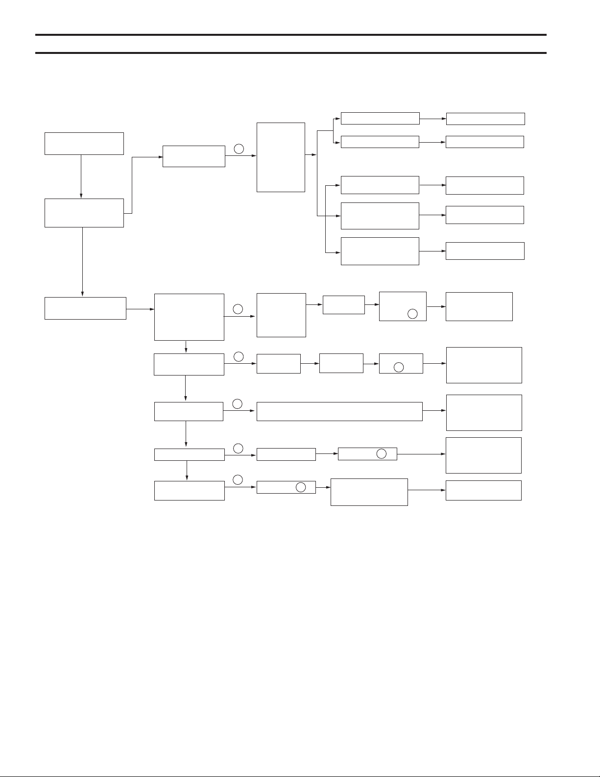
52
75D2525
DVM Series Direct Vent Gas Fireplace
OPERATION
Install batteries and/or
plug in the AC board
Flip the master switch
(rocker switch) to the
ON position
Press the ON button on
the Command Center
FAULT
No beep in about
8 seconds
No beep
or
no sound from the
valve indicating pilot
solenoid open
No sparking on
the pilot
Sparking doesn’t
continue
Pilot doesn’t light
Main burner doesn’t
light
DIAGNOSIS
Make sure
Command
Center and
the control
board are
connected by
a 2 feet or 15
feet cable
Check NG/LP
conversion cap
and control
board
connections
Check pilot
connections
The Control Board is having interference from the
surrounding metal (Ground)
Check gas supply
Go through
Battery polarity wrong?
LED on the Command
Center does not show
solid green?
The 5-pin connector on
the AC board broken or
bent?
AC plug is plugged to
AC mains?
Battery voltage low?
Using
battery?
Check valve
connections
Check power
supply (go
through )
A
E
Check
grounding
Go through
B
Go through
C
The sensor on the pilot
is not in the flame
(pilot flame too small)?
ACTION
Re-install batteries
Change batteries
Plug the AC plug to
AC mains
Repair or replace the
AC Board
Replace the AC Board
Replace the Control
Board or
Command Center
Sparking is happening
elsewhere (under the
pilot), re-install/replace
the pilot
Re-install the Control
Board, move it around
or change the
Control Board
Sparking is not in the
path of gas flow, adjust
sparker position or
replace the pilot
Adjust sensor position
or replace the pilot
After the beep
A
B
C
D
E
F
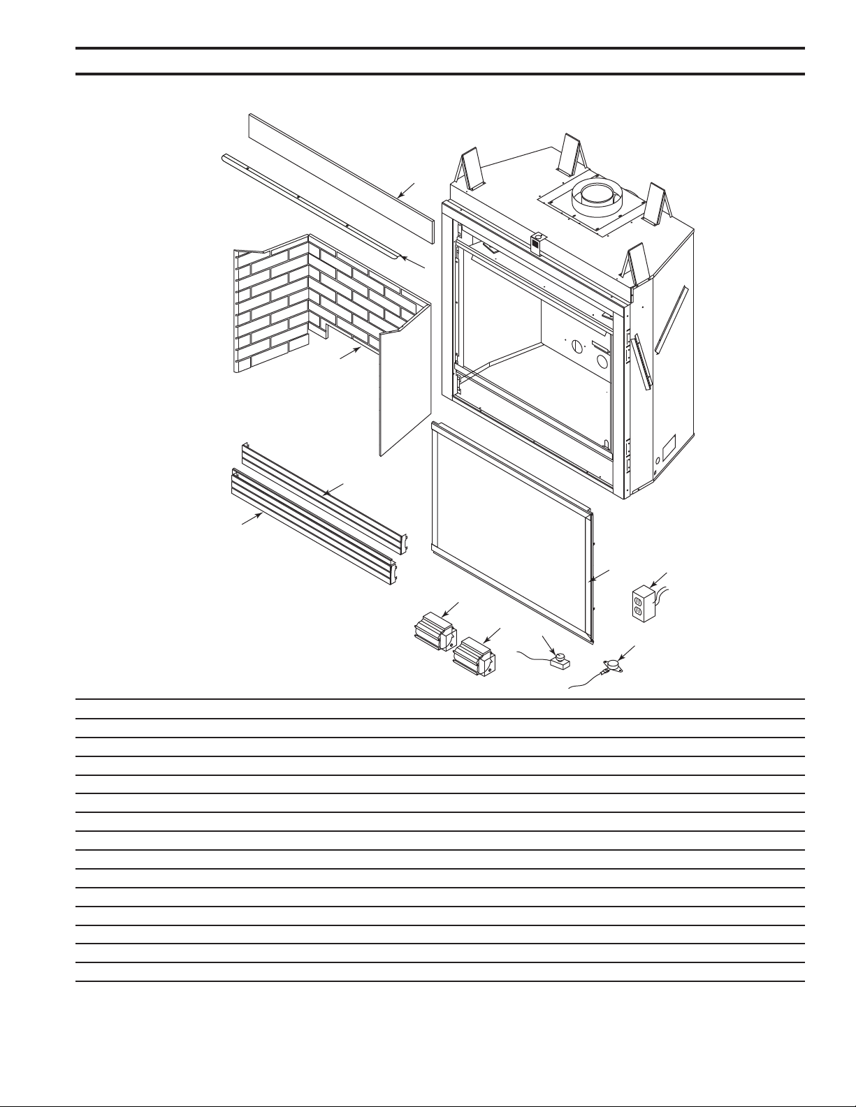
53
75D2525
DVM Series Direct Vent Gas Fireplace
1
5
3
2
4
7
10
6
9
8
8
1. Junction Box Assy. 1 26D2128K 26D2128K
2. Top Louver Assy. 1 56D2134K 56D2262K
3. Bottom Louver Door Assy. 1 56D2135K 56D2263K
4. Glass Frame Assy 1 56D2143K 56D2269K
5. Eyebrow 1 56D4041 56D4038
6. Insulation Board 1 56D2197 56D2216K
7. Firebrick - Tavern Brown 1 FBMDV500TB FBMDV600TB
7. Firebrick - Cottage Red 1 FBMDV500CR FBMDV600CR
8. Blower 1 56D2162K 56D2162K
9. Thermostat Sensor 1 26D2870K 26D2870K
10. Speed Control 1 26D0746K 26D0746K
8, 9 ,10 T-stat Blower w/ Speed Control 1 BLOTSDV BLOTSDV
8. SCS Blower Kit w/ Time Delay 1 BLOTBLDVSC BLOTBLDVSC
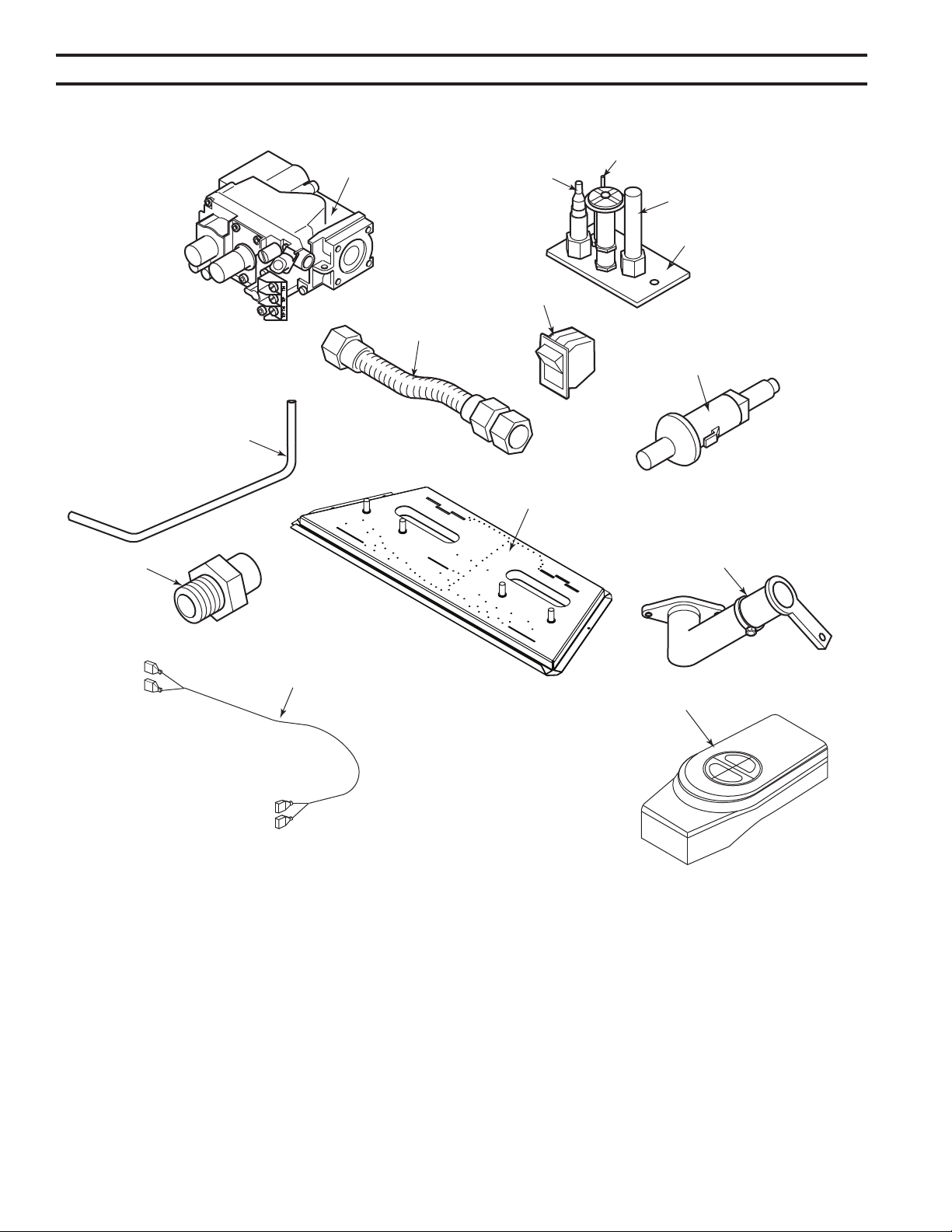
54
75D2525
DVM Series Direct Vent Gas Fireplace
1
2C
2I
2T
2
4
5
6
3
8
9
7
10
11,12,13,14,15,16

55
75D2525
DVM Series Direct Vent Gas Fireplace
1. Gas Valve Assy. 1 37D0117 37D0118 37D0117 37D0118
2. Pilot Assy. 1 37D0018 37D0019 37D0018 37D0019
2C. Replacement Thermocouple 1 37D1067 37D1067 37D1067 37D1067
2I. Replacement Igniter w/Wire 1 37D1069 37D1069 37D1069 37D1069
2T. Replacement Thermopile 1 37D1068 37D1068 37D1068 37D1068
3. Burner Tube 1 56D2175 56D2175 56D2175 56D2175
4. Flex Hose w/ Shutoff Valve 1 69D0030 69D0030 69D0030 69D0030
5. Rocker Switch 1 41D0048 41D0048 41D0048 41D0048
6. Piezo Igniter 1 14D0503 14D0503 14D0503 14D0503
7. Injector 1 57D1030 20H3144 56D0614 57D0680
8. Burner Assy. 1 75D2509 75D2509 75D2509 75D2509
9. Venturi 1 45D0006 45D0006 45D0006 45D0006
10. Wire Assy. 1 44D0500 44D0500 44D0500 44D0500
10. Wire Assy. 1 44D0501 44D0501 44D0501 44D0501
11. Thermostatic Remote Control 1 RCST/RCT/WWTD/RCSTE
12. On/Off Remote Control 1 RCB/RCBE/RCMT/WMTD
13. Full Function Remote Control 1 RCSTEB/RCSITE
14. Wall Switch 1 MVWS
15. Wired Thermostat Kit 1 WT
500DVM Kit #SCK500CKP
600DVM Kit #SCK600CKP
500DVM Kit #SCK500CKN
600DVM Kit #SCK600CKN
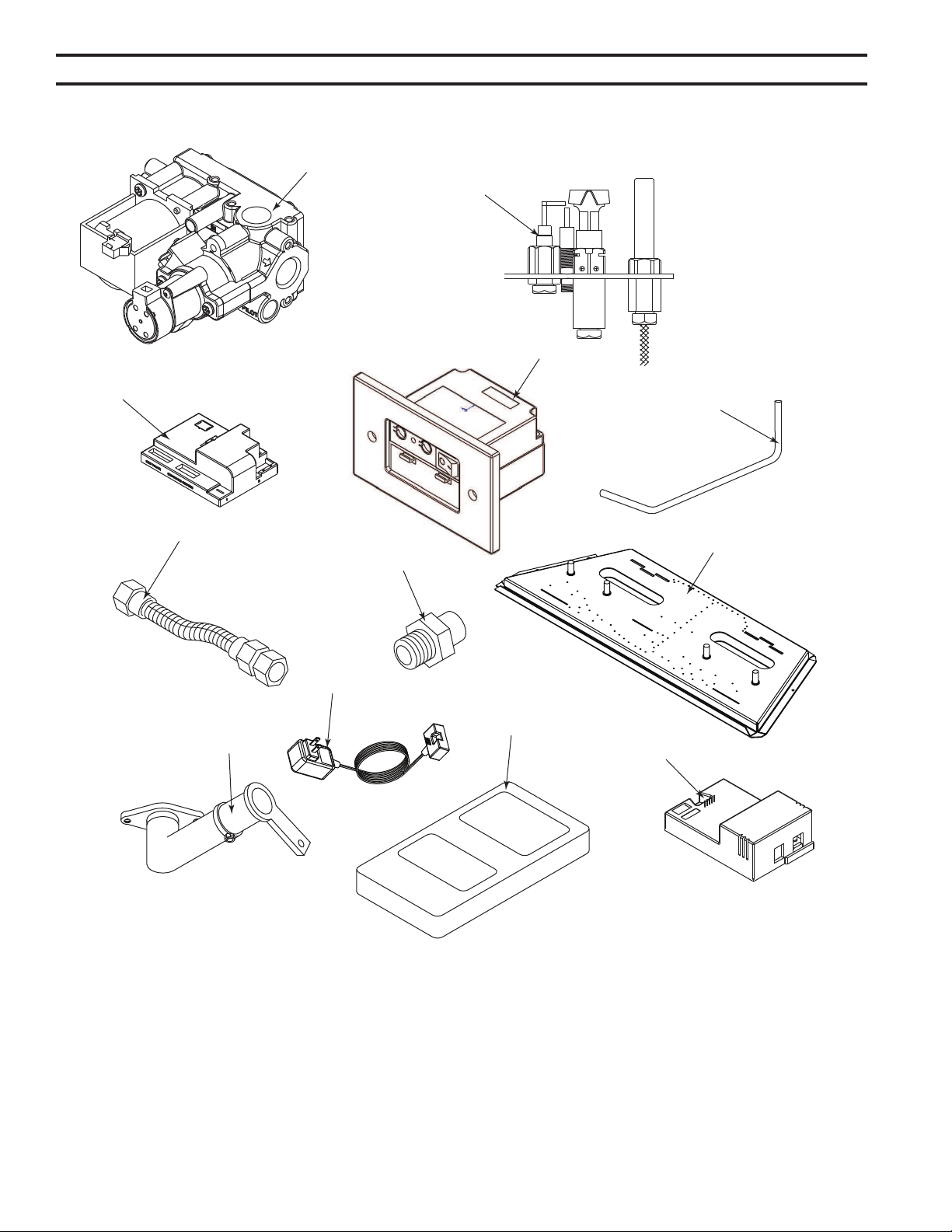
56
75D2525
DVM Series Direct Vent Gas Fireplace
1
2
3
4
19
5
6
7
8
9
13, 14, 15, 16, 17
12

57
75D2525
DVM Series Direct Vent Gas Fireplace
1. Gas Valve Assy. 1 80D0001 80D0002 80D0001 80D0002
2. Pilot Assy. 1 80D0006 80D0007 80D0006 80D0007
3. Control Box 1 80D0018 80D0019 80D0018 80D0019
4. Command Center 1 80D0005 80D0005 80D0005 80D0005
5. Burner Tube 1 56D3099 56D3099 56D3099 56D3099
6. Flex Hose w/ Shutoff Valve 1 69D0030 69D0030 69D0030 69D0030
7. Injector 1 57D1030 20H3144 56D0614 57D0680
8. Burner Assy. 1 75D2509 75D2509 75D2509 75D2509
9. Venturi 1 45D0006 45D0006 45D0006 45D0006
10. Wire Valve Control (not shown) 1 80D0010 80D0010 80D0010 80D0010
11. Wire Command Ctr. Control Box 2'
(not shown) 1 80D0008 80D0008 80D0008 80D0008
12. A/C Adapter (6 Volt) 1 80D0041 80D0041 80D0041 80D0041
13. Hand Held Remote Control RMSC
14. Hand Held Remote Control w/ Hi/Lo & T-stat RTSC
15. Touch Screen Remote w/Optional Light, Auxiliary and Blower Control TSFSC
16. Touch Screen Remote Hi/Lo and Timer TSMSC
17. Touch Screen Remote Hi/Lo and TStat TSTSC
18. SCS Wall Mount Extension Kit (15' wire, rough-in box, wall cover) (not shown) SCSWEK
19. SCS A/C Module (Opt. Blower, Light & Aux. Control) SCSACM
500DVM Kit #MDV500CKPS
600DVM Kit #MDV600CKPS
500DVM Kit #MDV500CKNS
600DVM Kit #MDV600CKNS
TSFSC must be used with SCS A/C Module to control
blower, lights and aux.
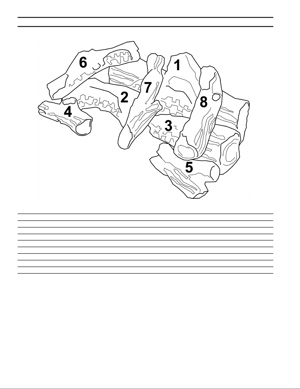
58
75D2525
DVM Series Direct Vent Gas Fireplace
1. Rear Log #1 1 75D2016 75D2016
2. Left Middle Log #2 1 75D2017 75D2017
3. Right Middle Log #3 1 75D2018 75D2018
4. Left Front Log #4 1 75D2019 75D2019
5. Right Front Log #5 1 75D2020 75D2020
6. Upper Left Log #6 1 75D2021 75D2021
7. Upper Middle Log #7 1 75D2022 75D2022
8. Upper Right Log #8 1 75D2023 75D2023
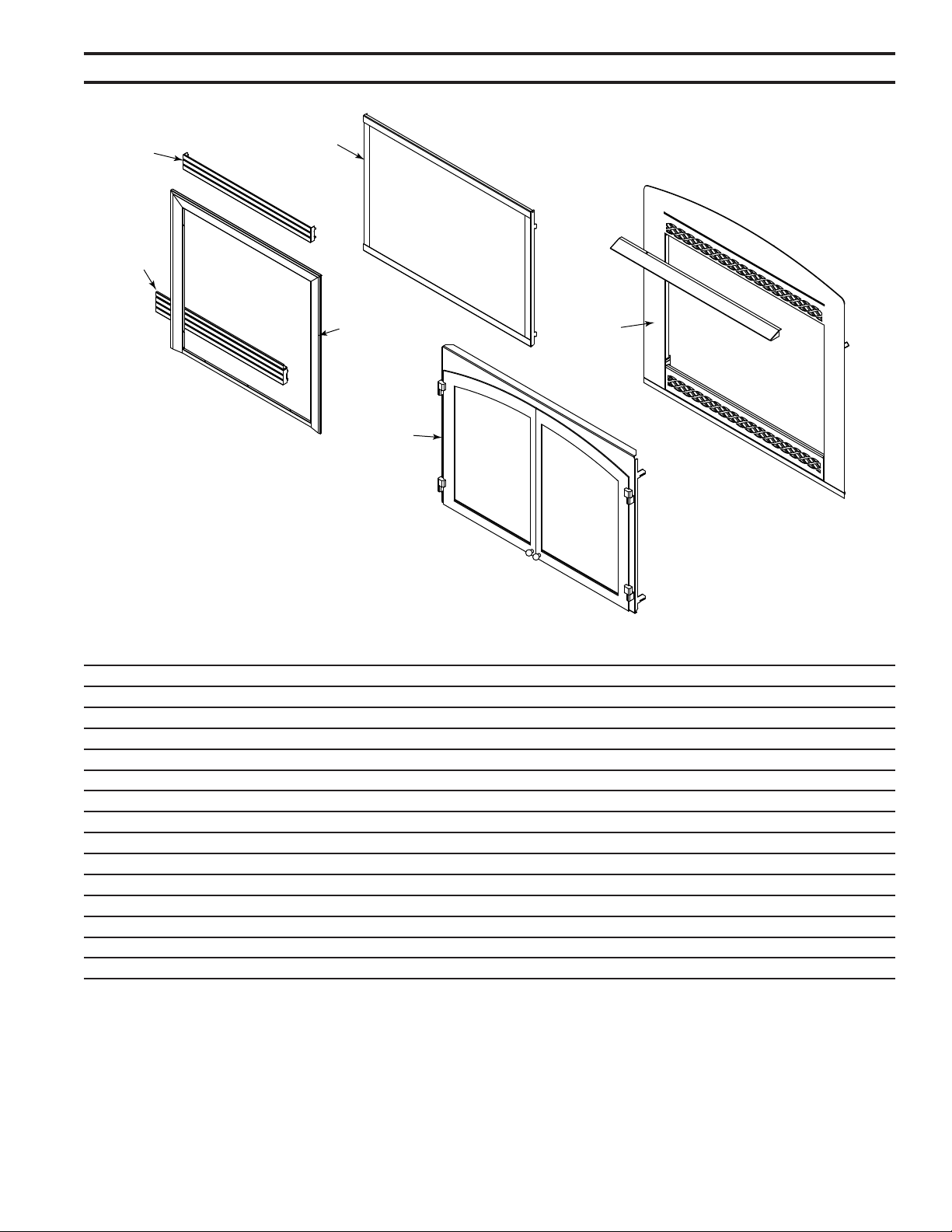
59
75D2525
DVM Series Direct Vent Gas Fireplace
1
2
2
3
4
5
1. Metal Trim - Brass 1 BRMTK500 BRMTK600
1. Metal Trim - Pewter 1 PWMTK500 PWMTK600
1. Metal Trim - Black 1 BLMTK500 BLMTK600
2. Brass Louvers 8 L36BRM L42BRM
2. Pewter Louvers 8 L36PWM L48PWM
3. Screen Frame - Black 1 500DVMSD 600DVMSD
4. Cabinet Door Frame - Black 1 VSDVC500CDFB VSDVC600CDFB
4. Cabinet Door Frame - Iron Age 1 VSDVC500CDFIA VSDVC600CDFIA
4. Cabinet Door w/Screen - Black 1 VSDVC500CDB VSDVC600CDB
4. Cabinet Door w/Screen - Iron Age 1 VSDVC500CDIA VSDVC600CDIA
5. Arched Front w/Lower Control Door - Black 1 BSDVC500AFB VSDVC600AFB
5. Arched Front w/Lower Control Door - Iron Age 1 VSDVC500AFIA VSDVC600AFIA
6. Forged Andiron 8C\v" (not shown) 1 FAI834 FAI834
7. Mesh Glass Cover (not shown) 1 BDV500SC BDV600SD
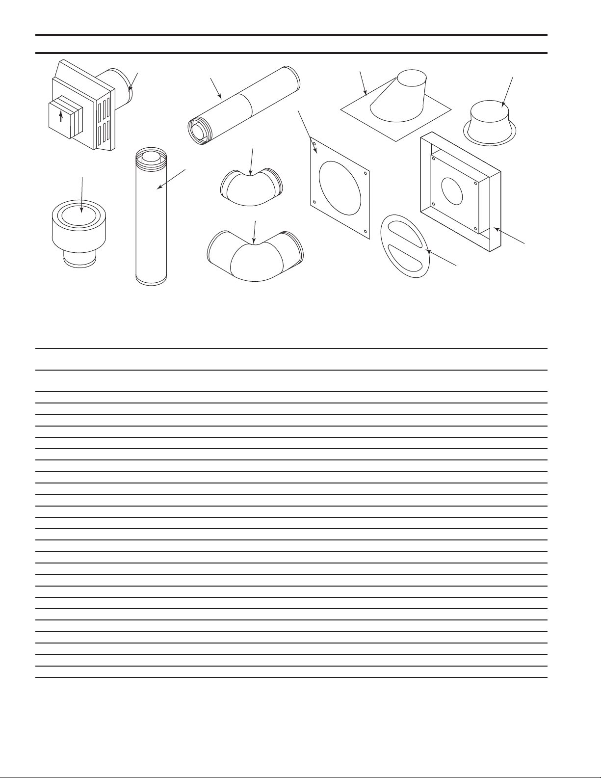
60
75D2525
DVM Series Direct Vent Gas Fireplace
HOT
1
2
3
4
5
6
9
7
8
11
10
1 1 Thru-roof Flexible Pipe Termination Kit with ex adapter TRFK -- -- --
24" rigid pipe, roof support 4" x 6
5
/8" and termination cap
1 1 Horizontal Square Termination Cap with built-in vinyl BHRTK BHRTK -- --
siding standoff, heat deector and restop
1 1 Square Horizontal Termination Cap 46DVA-HC 985 4DT-HC 4DHT
1 1 Round Horizontal Termination Cap 46DVS-HRCS -- -- --
1 1 Sconce Termination Cap (aluminum) 46DVA-HSC -- -- --
2 1 Low-Prole Vertical Termination Cap 46DVA-VC 980 4DT-VC 4DVT
3 6 6" Pipe Length (galvanized) 46DVA-06 908 4DT-06 4DV6
3 6 9" Pipe Length (galvanized) 46DVA-09 907 4DT-09 --
3 6 12" Pipe Length (galvanized) 46DVA-12 906 4DT-1 4D12
3 6 24" Pipe Length (galvanized) 46DVA-24 904 4DT-4 4D24
3 6 36" Pipe Length (galvanized) 46DVA-36 903 4DT-36 4D36
3 6 48" Pipe Length (galvanized) 46DVA-48 902 4DT-48 4D48
4 6 8
1
/2" Pipe Extension (galvanized) 46DVA-08A -- 4DT-AJ --
4 6 16" Pipe Extension (galvanized) 46DVA-16A -- 4DT-AJ14 --
5 6 45° Elbow (galvanized) 46DVA-E45 945 4DT-EL45 4D45L
6 6 90° Elbow (galvanized) 46DVA-E90 990 4DT-EL90 4D90L
7 6 Adjustable Roof Flashing 0/12 - 6/12 46DVA-F6 943 4DT-AF6 4DF
8 6 Storm Collar 46DVA-SC 953 4DT-SC 4F5C
9 6 1" Firestop 46DVA-FS 963 4DT-FS 4DF5
9 6 3" Firestop FS3 -- -- --
10 1 Vinyl Siding Standoff 46DVA-VSS 950 4DT-VS 4DVS
11 1 Restrictor Disk 45D0551 45D0551 -- --
1 Attic Insulation Shield 46DVA-IS -- -- --
6 Steep Roof Flashing 7/12 - 12/12 46DVA-F12 943S -- --
8 Horizontal Termination with 1" restop BHRT/8 -- -- --
8 Flex Adapter Starter DVFFA/8 -- -- --
Reducer Adapter (from 4" x 7") MBSPA -- -- 4DMA
B\,
Z\x
For more information about, or instructions for, the venting components referenced, please contact the component manufacturer:
Selkirk Corporation: www. selkirkcorp.com or 800-992-8368; Simpson Duravent: www. duravent.com or 800-835-4429;
Metal-Fab, Inc.: www.metal-fabinc.com or 316-943-2351
61
75D2525
DVM Series Direct Vent Gas Fireplace
1 1 Horizontal High Wind Termination Cap 58DVA-HC 1285 5DT-HC --
1 1 Horizontal Termination Cap w/Built-In Vinyl Siding BHR8TK9 --
Standoff Heat Deector, Firestop and Adjustable
Pipe 11" to 14
5
/8"
1 1 Horizontal Termination Cap Built-In Vinyl Siding Standoff, BHS8TK --
Heat Deector, Firestop, 90° Elbow and Adjustable
Pipe 11" to 14
5
/8"
1 1 Horizontal Termination Cap w/Built-In Vinyl Siding Standoff, BHSF8TKA --
Heat Deector, Firestop, Flexible Pipe 20" to 48", Adapter
1 8 Horizontal Termination w/ 1" Firestop BHRST/8
1 1 Horizontal Temination Cap 5DHT
2 1 Vertical Termination 58DVA-VC 1280 5DT-VC 5DVT
3 4 6" Pipe Length 58DVA-06 1208 5DT-06 5D6
3 4 9" Pipe Length 58DVA-09 1207 5DT-09
3 4 12" Pipe Length 58DVA-12 1206 5DT-12 5D12
3 4 24" Pipe Length 58DVA-24 1204 5DT-24 5D24
3 4 36" Pipe Length 58DVA-36 1203 5DT-36 5D36
3 4 48" Pipe Length 58DVA-48 1202 5DT-48 5D48
4 4 8
1
/2" Pipe Extension 58DVA-08A -- 5DT-AJ
4 4 16" Pipe Extension 58DVA-16A -- --
5 4 45° Elbow 58DVA-E45 1245 5DT-EL45 5D456
5 4 45° Swivel Elbow -- -- 5DT-EL45
6 4 90° Elbow 58DVA-E90 1290 5DT-EL90S 5D906
6 4 90° Swivel Elbow -- 1290G 5DT-EL90S
7 6 Flashing, 0/12 to 6/12 Roof Pitch 58DVA-F6 1243 5DT-AF6 5DF
7 Steep Roof Flashing 58DVA-F12 1243S --
8 6 Storm Collar 58DVA-SC 1253 5DT-SC 5DSC
9 4 Firestop 58DVA-FS 1263 5DT-FS 5DFS
9 3" Firestop FS38 FS38 --
10 1 Vinyl Siding Standoff 58DVA-VSS 1250 5DT-VS 5DVS
11 Attic Insulation Shield (not shown) 58DVA-IS -- --
12 8 Flex Adapter Starter (not shown) DVFF8A/8 -- --
For more information about, or instructions for, the venting components referenced above, please contact
the component manufaturer:
Selkirk Corporation: www. selkirkcorp.com or 800-992-8368
Simpson Duravent: www. duravent.com or 800-835-4429
Metal-Fab, Inc.: www.metal-fabinc.com or 316-943-2351
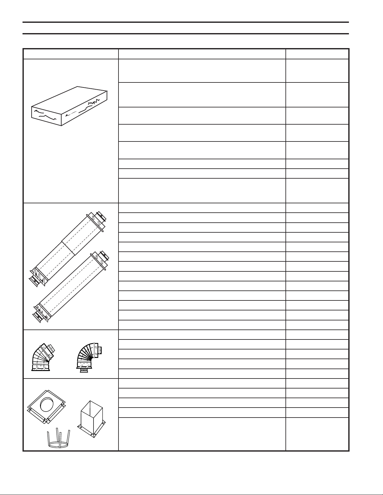
62
75D2525
DVM Series Direct Vent Gas Fireplace
Horizontal Vent Termination Kits Rear Vent Hot Touch Termination Kit w/ 10" to 16" 7TBRHTK
Adjustable Termination Pipe, Firestop, and Hot Touch
Termination w/ Siding Shield
Up and Out Side Wall Termination Kit w/ 10" to 16" 7TDVSCTK
Adjustable Termination Pipe, 90° Elbow, Firestop, and
Cool Touch Termination w/ Siding Shield
Rear Vent Cool Touch Termination w/ Siding Shield for 7TRVCT/8
Straight-out Applications and Firestop - 8 pack
Rear Vent Hot Touch Termination w/ Siding Shield for 7TRVHT/8
Straight-out Applications and Firestop - 8 pack
Termination Guard for 7" T.L. Rear Vent Hot Touch 7TRVTG
Terminations 97TRVT/7TSVKT)
Snorkel Termination 7TDVSNORK
7" T.L. DVRTSB Termination Screen Guard 7TBSG
Up and Out Starter Kit w/ 40" Flex Pipe, Firestop, Cool 7FDVSCTK
Touch Termination w/ Siding Shield, and 2 ea. Clamp
Bands
Twist Lock Pipe 20" Termination Pipe - 8 pack 7TDVP20/8
10" - 16" Adjustable Termination Pipe - 4 pack 7TDVPA/4
12" - 18" Adjustable Vent Length 7TDVP1218
35" - 64" Adjustable Vent Length 7TDVP3564
8" Vent Pipe - 4 pack 7TDVP8/4
12" Vent Pipe - 4 pack 7TDVP12/4
24" Vent Pipe - 4 pack 7TDVP24/4
36" Vent Pipe 7TDVP36
36" Vent Pipe - 30 pack 7TDVP36/30
48" Vent Pipe 7TDVP48
48" Vent Pipe - 30 pack 7TDVP48/30
5" x 8" to 4" x 7" Adapter 7TDVP58
Flex Adapter Starter Kit DVFFA/8
Twist Lock Elbows 45° Elbow for Vertical/Horizontal Offset 7TDV45
45° Elbow for Vertical Offsets - 8 pack 7TDV45/8
90° Elbow for Vertical/Horizontal Offset 7TDV90
90° Elbow for Vertical/Horizontal Offset - 8 pack 7TDV90/8
Shields and Supports 1" Firestop 7DV1FS
3" Firestop 7DV3FS
1" Attic Insulation Shield 7DV1AIS
Combination Horizontal Offset/Roof Support 7DVCS
Venting Components
Telescope vent
2/25/99 djt
10/20/99 twist lock
3/10/10 T-lock
584F
Venting Components
Pipe sections
2/25/99 djt
10/20/99 twist lock
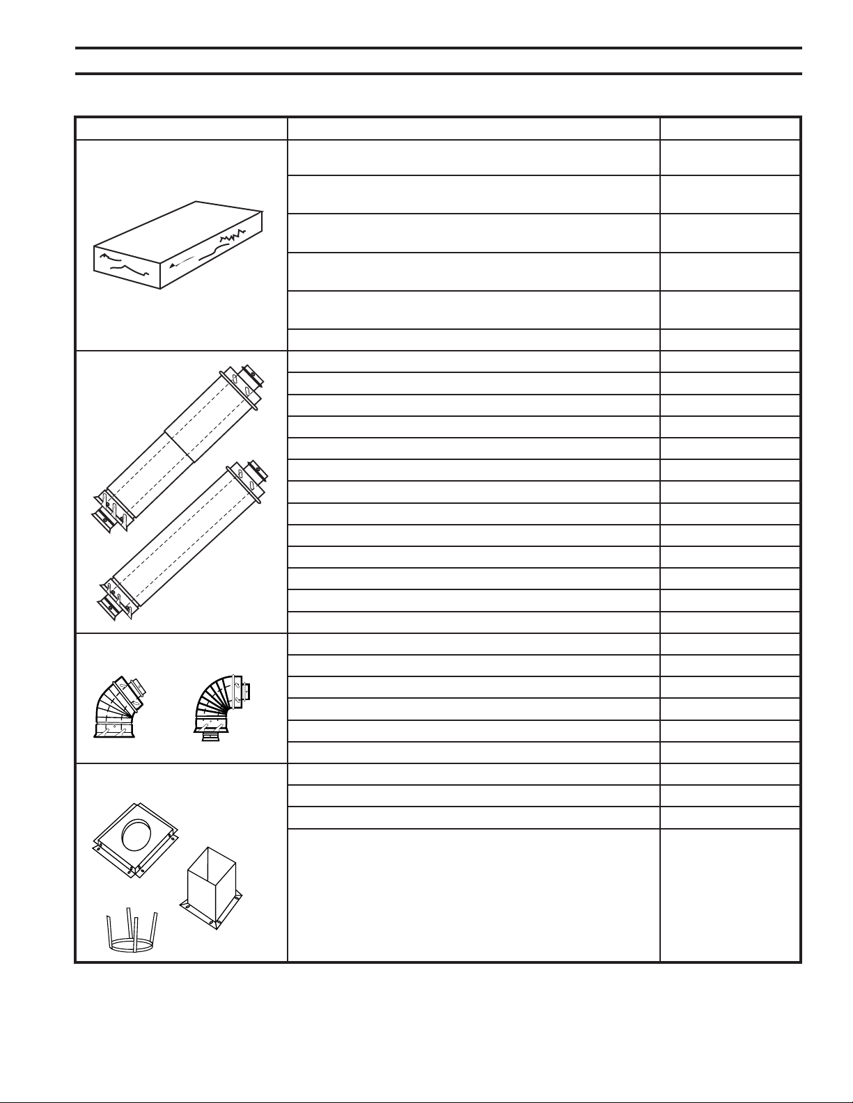
63
75D2525
DVM Series Direct Vent Gas Fireplace
Vertical Vent Termination Kits Vertical Vent Termination w/ Storm Collar 7TDVSKV
(ashing NOT included)
Vertical Vent Termination w/ Storm Collar - 8 pack 7TDVSKV/8
(ashing NOT included)
Vertical Vent Termination w/ 1/12 - 6/12 Flashing, Storm 7TDVSKVA*
Collar and Ceiling Support Kit
Vertical Vent Termination w/ 6/12 - 12/12 Flashing, 7TDVSKVB*
Storm Collar and Ceiling Support Kit
Vertical Vent Termination w/ Flat Flashing, Storm Collar 7TDVSKVF*
and Ceiling Support Kit
Twist Lock Pipe 20" Rigid Pipe - single pack 7TDVP20
30" Flex Pipe - single pack 7FDVP30
12" - 18" Adjustable Vent Length 7TDVP1218
35" - 64" Adjustable Vent Length 7TDVP3564
8" Vent Pipe - 4 pack 7TDVP8/4
12" Vent Pipe - 4 pack 7TDVP12/4
24" Vent Pipe - 4 pack 7TDVP24/4
36" Vent Pipe 7TDVP36
36" Vent Pipe - 30 pack 7TDVP36/30
48" Vent Pipe 7TDVP48
48" Vent Pipe - 30 pack 7TDVP48/30
5" x 8" to 4" x 7" Adapter 7TDVP58
Flex Adapter Starter Kit DVFFA/8
Twist Lock Elbows 45° Elbow for Vertical/Horizontal Offset 7TDV45
45° Elbow for Vertical Offsets - 8 pack 7TDV45/8
90° Elbow for Vertical/Horizontal Offset 7TDV90
90° Elbow for Vertical/Horizontal Offset - 8 pack 7TDV90/8
Shields and Supports 1" Firestop 7DV1FS
1" Attic Insulation Shield 7DV1AIS
Combination Horizontal Offset/Roof Support 7DVCS
584E
Venting Components
Telescope vent
2/25/99 djt
10/20/99 twist lock
584F
Venting Components
Pipe sections
2/25/99 djt
10/20/99 twist lock

64
75D2525
DVM Series Direct Vent Gas Fireplace

65
75D2525
DVM Series Direct Vent Gas Fireplace

66
75D2525
DVM Series Direct Vent Gas Fireplace
This product must be installed by a licensed plumber or gas tter
when installed within the Commonwealth of Massachusetts.
Any residence with a direct vent product must have a CO
detector installed in the residence.
Installation of the replace or vented gas log in the State of
Massachusetts requires the damper to be permanently removed
or welded in the fully open position.
In addition, a naturally vented gas log may not be installed in a
bedroom or bathroom in the State of Massachusetts.
Flex line installation must not exceed 36 inches and must have
a T shutoff valve.
This product must be installed by a licensed plumber or gas tter
when installed within the Commonwealth of Massachusetts.
In addition, vent free products may not be installed in a
bedroom or bathroom regardless of size or type in the State of
Massachusetts.
Flex line installation must not exceed 36 inches and must have
a T shutoff valve.
(2) Revise 10.8.3 by adding the following additional
requirements:
(a) For all side wall horizontally vented gas fueled
equipment installed in every dwelling, building or structure used
in whole or in part for residential purposes, including those
owned or operated by the Commonwealth and where the side
wall exhaust vent termination is less than seven (7) feet above
nished grade in the area of the venting, including but not
limited to decks and porches, the following requirements shall
be satised:
1. At the time
of installation of the side wall horizontal vented gas fueled
equipment, the installing plumber or gas tter shall observe
that a hard wired carbon monoxide detector with an alarm and
battery back-up is installed on the oor level where the gas
equipment is to be installed. In addition, the installing plumber
or gas tter shall observe that a battery operated or hard wired
carbon monoxide detector with an alarm is installed on each
additional level of the dwelling, building or structure served by
the side wall horizontal vented gas fueled equipment. It shall be
the responsibility of the property owner to secure the services of
qualied licensed professionals for the installation of hard wired
carbon monoxide detectors
a. In the event that the side wall horizontally vented gas
fueled equipment is installed in a crawl space or an attic, the
hard wired carbon monoxide detector with alarm and battery
back-up may be installed on the next adjacent oor level.
b. In the event that the requirements of this subdivision
can not be met at the time of completion of installation, the
owner shall have a period of thirty (30) days to comply with the
above requirements; provided, however, that during said thirty
(30) day period, a battery operated carbon monoxide detector
with an alarm shall be installed.
2. Each carbon
monoxide detector as required in accordance with the above
provisions shall comply with NFPA 720 and be ANSI/UL 2034
listed and IAS certied.
3. A metal or plastic identication plate shall be
permanently mounted to the exterior of the building at a
minimum height of eight (8) feet above grade directly in line
with the exhaust vent terminal for the horizontally vented
gas fueled heating appliance or equipment. The sign shall
read, in print size no less than one-half (1/2) inch in size,
“GAS VENT DIRECTLY BELOW. KEEP CLEAR OF ALL
OBSTRUCTIONS.”
4. The state or local gas inspector of the side
wall horizontally vented gas fueled equipment shall not
approve the installation unless, upon inspection, the inspector
observes carbon monoxide detectors and signage installed
in accordance with the provisions of 248 CMR 5.08(2)(a)1
through 4.
(b) The following equipment is exempt from
248 CMR 5.08(2)(a)1 through 4:
1. The equipment listed in Chapter 10 entitled "Equipment
Not Required To Be Vented" in the most current edition of
NFPA 54 as adopted by the Board; and
2. Product Approved side wall horizontally vented gas fueled
equipment installed in a room or structure separate from the
dwelling, building or structure used in whole or in part for
residential purposes.
(c)
When the manufacturer of Product
Approved side wall horizontally vented gas equipment provides
a venting system design or venting system components with
the equipment, the instructions provided by the manufacturer
for installation of the equipment and the venting system shall
include:
1. Detailed instructions for the installation of the venting
system design or the venting system components; and
2. A complete parts list for the venting system design or
venting system.
(d)
When the manufacturer of
a Product Approved side wall horizontally vented gas fueled
equipment does not provide the parts for venting the ue
gases, but identies “special venting systems,” the following
requirements shall be satised by the manufacturer:
1. The referenced "special venting system" instructions shall
be included with the appliance or equipment installation
instructions; and
2. The “special venting systems” shall be Product Approved
by the Board, and the instructions for that system shall include
a parts list and detailed installation instructions.
(e) A copy of all installation instructions for all Product
Approved side wall horizontally vented gas fueled equipment,
all venting instructions, all parts lists for venting instructions,
and/or all venting design

67
75D2525
DVM Series Direct Vent Gas Fireplace
The following components are warranted for life to the original owner, subject to proof of pur-
chase: Firebox, Combustion Chamber, Heat Exchanger, Grate and Stainless Steel Burners.
The following components are warranted ve (5) years to the original owner, subject of proof
of purchase: Ceramic Fiber Logs.
MHSC warrants the components and materials in your gas appliance to be free from manufac-
turing and material defects for a period of two years from date of installation. After installation,
if any of the components manufactured by MHSC in the appliance are found to be defective in
materials or workmanship, MHSC will, at its option, replace or repair the defective components
at no charge to the original owner. MHSC will also pay for reasonable labor costs incurred in
replacing or repairing such components for a period of two years from date of installation. Any
products presented for warranty repair must be accompanied by a dated proof of purchase.
This Limited Lifetime Warranty will be void if the appliance in not installed by a qualied in-
staller in accordance with the installation instructions. The Limited Lifetime Warranty will also
be void if the appliance is not operated and maintained according to the operating instructions
supplied with the appliance, and does not extend to (1) rebox/burner assembly damage by
accident, neglect, misuse, abuse, alterations, negligence of others, including the installation
thereof by unqualied installers, (2) the costs of removal, reinstallation or transportation of
defective parts on the appliance, or (3) incidental or consequential damage. All service work
must be performed by an authorized service representative.
This warranty is expressly in lieu of other warranties, express or implied, including the war-
ranty of merchantability of tness for purpose and of all other obligations or liabilities. MHSC
does not assume for it any other obligations or liabilities in connection with sale or use of the
appliance. It states that do not allow limitations on how long an implied warranty lasts, or do
not allow exclusion of indirect damage, those limitations of exclusions may not apply to you.
You may also have additional rights not covered in the Limited Lifetime Warranty.
MHSC reserves the right to investigate any and all the claims against the Limited Lifetime
Warranty and decide upon method of settlement.
1. Contact your supplier. Make sure you have your warranty, your sales receipt and
the model/serial number of your MHSC product.
2. DO NOT ATTEMPT TO DO ANY SERVICE WORK YOURSELF.
149 Cleveland Drive • Paris, Kentucky 40361
www.mhsc.com
Based on CSA P.4.1-09
500DVMNV 71.7
500DVMPV 77.9
500DVMNSC 76.4
500DVMPSC 82.1
600DVMNV 67.6
600DVMPV 74.3
600DVMNSC 71.0
600DVMPSC 77.7